US4398290A - Process and apparatus for digital data communication using packet switching - Google Patents
Process and apparatus for digital data communication using packet switchingDownload PDFInfo
- Publication number
- US4398290A US4398290AUS06/270,623US27062381AUS4398290AUS 4398290 AUS4398290 AUS 4398290AUS 27062381 AUS27062381 AUS 27062381AUS 4398290 AUS4398290 AUS 4398290A
- Authority
- US
- United States
- Prior art keywords
- packets
- packet
- data
- frame
- location
- Prior art date
- Legal status (The legal status is an assumption and is not a legal conclusion. Google has not performed a legal analysis and makes no representation as to the accuracy of the status listed.)
- Expired - Lifetime
Links
Images

Classifications
- H—ELECTRICITY
- H04—ELECTRIC COMMUNICATION TECHNIQUE
- H04J—MULTIPLEX COMMUNICATION
- H04J3/00—Time-division multiplex systems
- H04J3/24—Time-division multiplex systems in which the allocation is indicated by an address the different channels being transmitted sequentially
Definitions
- the inventionrelates to digital communication using packet switching and is particularly, but not exclusively, suitable for use in networks for transmission and diffusion of digital data representing sound signals, such as voice and high fidelity mono- and stereo-sounds.
- the first step in the communication processcomprises distributing the digital data into "packets", consisting of an opening part, called the prefix p, and an information useful part.
- the prefixprovides indications defining the structure of the useful part.
- the useful partcomprises a short length fraction of the message, which consists of a sequence of words each having x bits and representing the signal to be transferred. When the data are sound signals, the words typically each represent a quantized sample in digital form.
- Reconstitution at the receiveris achieved by assembling a fixed predetermined number of words to form a unit which may be called a "digital frame", having a constant length l, having an opening portion consisting of a word of particular and identifiable construction, which will be called "frame lock word”. That lock word makes it possible for the receiver to break up the received sequence into x-bit words correctly.
- the sequenceincludes the frame lock word at evenly distributed intervals.
- each packetis an autonomous entity. Routing is transparent to the users and to the system used for transmission, storing and/or broadcasting the sequence of digital data. If the communication network has several alternative routes, packet switching leads to optimum use of the network capacity.
- the data insertion techniqueswhich are in present use (in which the only limitation is in respect of the maximum number of bits in a packet) result in a loss of continuity in the digital service if a packet is lost.
- a loss of a packetrelated for instance to a faulty recovery of the data in the prefix, results in the loss of all data in the useful part of the packet. Since the length of the useful part is variable, the loss of a packet frequently results into a change of the periodical repetition of the digital sequence.
- the receiverdetects an incorrect phase of the frame lock word with respect to its local clock. A resynchronisation procedure which implies searching for a structure corresponding to the frame lock word is necessary and the communication is broken during the search.
- the arrangement of digital data in short packets having a fixed length Lis rendered possible by implicitly programming the format of the packets in the multiplexer and demultiplexer provided for sending and receiving data, i.e. at both ends of the communication link (the word "implicit” meaning predetermined at both ends without any requirement for transmission and/or acknowledgment of commands prior to data transmission).
- the above defined constructionmakes it possible to avoid any loss of information in addition to that contained in the useful part of the lost packet(s).
- the number of lost packetsmay be determined by inserting a continuity index word into the prefix of each packet or into the frame locking word at the sender location and then checking the continuity of the index words upon reception of the packets.
- substitution wordswhen there is a certain amount of correlation between successive words, substitution words are generated in replacement of the lost words.
- the substitution wordsmay be generated using as a basis the words before and after the lost words.
- Such an approachmay particularly be used when the words represent successive samples of a sound signal.
- the processtakes advantage of the fact the number of missing words may be computed, since each frame has a constant number of words and the lost packet has a constant and known number of frames (which however may be so assembled that a packet contains part only of the first and last frames).
- the wordsi.e. samples, which are generated and reinserted upon packet disassembly in the receiving facility or terminal are used to mitigate the effects of the loss of continuity in communication. If a single short packet, having k frames of each n words each representing a sample are lost, n ⁇ k samples are generated and inserted between the last sample N received before the communication is broken and the first sample N+nk+1 received after recovery.
- FIG. 1is a diagram illustrating the general structure of a packet
- FIG. 2indicates the overall structure of a digital service frame comprising a frame lock word
- FIG. 3illustrates how a message is broken up into short packets, according to the invention
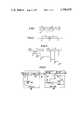
- FIGS. 4A and 4Bschematically illustrate the consequences of the loss of a packet in a system according to the invention
- FIG. 5is a simplified block diagram of a communication apparatus according to the invention.
- FIG. 6is a simplified block diagram of a modified embodiment including means for inserting and monitoring continuity index words
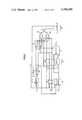
- FIG. 7is a block diagram of a restoration system.
- each independent packetcomprises a prefix of length p and a useful part of length L.
- the useful partis a sequential arrangement of successive digital frames whose length l is constant in the process of the invention.
- Each frameincludes a fixed and predetermined number n of words each consisting of x bits. It will be assumed that analog data are to be communicated; then each word is a representation of a sample of the analog data.
- Each framehas an opening portion consisting of a frame lock word 11 which enables the receiving terminal to disassemble the received sequence.
- the frame lock words 11have the same location in each of the successive packets.
- a comparison between FIGS. 4A and 4Bmakes it clear that, upon loss of a packet 10a, the time synchronization of the frame lock word is not lost.
- the frame lock word 11 of frame No. 8appears after the frame lock word of frame No. 4, after a time delay which is a multiple of the repetition period of the lock word in a packet.
- the apparatuscomprises a transmitter terminal 30 and a receiver terminal 20.
- the packets delivered by the transmitter or sender terminal 30are fed in sequence to the receiver 20 through a communication network which may be of any type. That network can include:
- a broadcasting transmitterconnected to one or more broadcasting receivers by wire or radio means;
- a recorderwhich delivers a physical data bearing support which is later used on a reading apparatus.
- the communication networkmay include a plurality of nodes which have a store and forward capability and allocate the available circuits dynamically depending upon the received packets destination.
- the digital signal which is applied at input 34is inserted by a multiplexer 31 into the frame structure defined by a time base or clock 32.
- the length l of the frameis a sub-multiple of the length L of the useful part of the packets.
- the digital sequence which appears at the output of multiplexer 31is applied to a coupler 33 which assembles the data into packets.
- the packetsare applied to a channel or network 40 for transmission broadcasting or recording.
- the receiver terminal 20which is connected to the output of a network terminal, a broadcasting receiver or a record reader constituting the output unit of channel 40, receives the digital signal.
- the input unit of the receiver terminal 20consists of a packet demultiplexer 21 which disassembles the packets and only delivers the useful digital sequence to the input of a comparator 22 which searches for the configuration of the frame lock word in the sequence. That configuration is stored in a memory built in the comparator 22.
- the comparatorfinds that configuration at even intervals, equal to the length l of each frame, under normal condition.
- Each time the comparator finds the wordit delivers a rephasing pulse to a local or output time base 23.
- the time base 23sends periodical signals to a signal demultiplexer 24 which receives the digital data from demultiplexer 21 on a data input.
- the recovered digital dataappear on output 25.
- the loss of a packetresults in a data loss which is not mitigated.
- meansare provided which give an indication of the number of packets which were lost, and consequently the damage caused to communication. It additionally includes means for reducing the consequences of such damage.
- the transmitter terminal 30comprises an incrementation counter 35 which generates a continuity index.
- Separate meanswhich are schematically represented by a switch 36, make it possible to insert the index either into the frame multiplexer 31 whereby an index word is inserted into each frame, or into coupler 33 whereby the index is inserted into each prefix.
- the continuity indexis read out either by the packet demultiplexer 21 (if associated with the prefix), or by the demultiplexer 24 (if associated with the frame).
- the indexis compared with the continuity index received immediately beforehand in a continuity break detector 26. Any incrementation break, which is confirmed by comparison with the next continuity index supplied by the demultiplexer 21 or 24, generates an alarm at an output 27.
- nK samplesare generated which are inserted between the last sample N received before loss and the first sample N+nK+1 received after restoration.
- each word of x bitsrepresents a digital sound signal sample.
- Each sampleis the quantized value of an analog value measured at time intervals distributed at a sampling frequency.
- S ithe sample of serial number i will be represented by the doublet (S i , A i ).
- the restoration system incorporated in the receivermay have the construction shown in FIG. 7. It comprises an input memory for temporarily storing each sample in turn.
- the memorycomprises:
- a flip-flop 42connected to receive the bit S i representative of the sign
- a shift register 41comprising x-1+nk/2 stages, connected so that its x-1 head stages are loaded in parallel by A i (x designating the number of bits per sample).
- a clock signal representative of the sampling timingis applied to the clock input H of flip-flop 42 and to the loading control input of register 41.
- Flip-flop 42 and register 41respectively drive a flip-flop 52 and a shift register 51 having x-1+nk/2 positions.
- the sample input timing signalis also applied to the clock input of flip-flop 52 and to the loading input of register 51; as a consequence, the contents of flip-flop 42 are stored in flip-flop 52 and the contents of the x-1 lower stages of register 41 are loaded in parallel into the x-1 upper stages of register 51.
- the sample timing signalis also applied to a generator 43 which supplies, in response to each timing pulse, nk successive pulses to a selector 44.
- This selectorseparates the nk pulses into two trains.
- the first train formed from the first nk/2 pulsesis applied to a divider-by-two 45.
- the second train, formed from the last nk/2 pulses,is applied to a divider-by-two 46.
- the first trainis also applied to register 51 so as to cause downward shift of the contents of this register.
- the second trainis applied to register 41 and causes upward shift of the contents of this register.
- the systemalso comprises a multiplexer 47 having two sets of x-1 inputs and having x-1 outputs.
- the inputs of multiplexer 47are connected to registers 41 and 51 so that the first set of inputs is loaded by the x-1 upper stages of register 41 and the second set of inputs by the x-1 upper stages of register 51.
- the two outputs of selector 44are connected to multiplexer 47 so as to separate the first nk/2 pulses from the last nk/2 pulses.
- the outputs of storage flip-flops 42 and 52are connected to two sets of enabling gates 48 and 49, which have the same construction.
- the set of gates 48for example comprises, on each output of flip-flop 42, an AND gate; the enabling input of one gate is connected to the Q output of divider 46 and the enabling input of the other to the Q output of divider 46.
- An OR gate 53receives the outputs of the two sets of gates 48 and 49 and applies them to one of the inputs of an acknowledgement register 54.
- the clock input H of register 54is connected to receive the pulses from a NOR gate 55.
- the two inputs of NOR gate 55are connected to receive signals representative of the input timing of the samples and to receive pulses from generator 43 through an enabling gate 56, respectively.
- Gate 56is an AND gate whose enabling input is connected so as to receive the alarm signal from the continuity break detector 26 (FIG. 6).
- Register 54is also connected to the x-1 outputs of multiplexer 47, representing the amplitude of the reconstituted sample.
- nk samplesto be created as a substitution for the nk samples missing between sample N and sample N+nk+1. These samples appear during the time interval when the enabling signal is applied to AND gate 56, i.e. between acknowledgements of the arrivals of the Nth and of the N+1th sample.
Landscapes
- Engineering & Computer Science (AREA)
- Computer Hardware Design (AREA)
- Computer Networks & Wireless Communication (AREA)
- Signal Processing (AREA)
- Data Exchanges In Wide-Area Networks (AREA)
- Communication Control (AREA)
- Transmission Systems Not Characterized By The Medium Used For Transmission (AREA)
- Time-Division Multiplex Systems (AREA)
Abstract
Description
Claims (6)
Applications Claiming Priority (2)
| Application Number | Priority Date | Filing Date | Title |
|---|---|---|---|
| FR8012672 | 1980-06-06 | ||
| FR8012672AFR2484174B1 (en) | 1980-06-06 | 1980-06-06 | METHOD AND DEVICE FOR INSERTING DIGITAL DATA IN PACKET FORM, AND INSTALLATION INCLUDING APPLICATION |
Publications (1)
| Publication Number | Publication Date |
|---|---|
| US4398290Atrue US4398290A (en) | 1983-08-09 |
Family
ID=9242808
Family Applications (1)
| Application Number | Title | Priority Date | Filing Date |
|---|---|---|---|
| US06/270,623Expired - LifetimeUS4398290A (en) | 1980-06-06 | 1981-06-04 | Process and apparatus for digital data communication using packet switching |
Country Status (6)
| Country | Link |
|---|---|
| US (1) | US4398290A (en) |
| EP (1) | EP0041895B1 (en) |
| JP (1) | JPS5725751A (en) |
| CA (1) | CA1169937A (en) |
| DE (1) | DE3167423D1 (en) |
| FR (1) | FR2484174B1 (en) |
Cited By (15)
| Publication number | Priority date | Publication date | Assignee | Title |
|---|---|---|---|---|
| US4551834A (en)* | 1983-10-25 | 1985-11-05 | U.S. Philips Corporation | Method and system for communicating over an open communication network |
| US4554660A (en)* | 1981-10-15 | 1985-11-19 | L'Etat Francais, represente par le Ministre des P.T.A. (Centre National d'Et | One-way data transmission system |
| US4561090A (en)* | 1983-05-18 | 1985-12-24 | At&T Bell Laboratories | Integrated self-checking packet switch node |
| US4589109A (en)* | 1983-04-15 | 1986-05-13 | British Broadcasting Corporation | Multiplexed digital data transmission |
| US4611323A (en)* | 1983-05-24 | 1986-09-09 | Ant Nachrichtentechnik Gmbh | Method for transmitting digitally coded analog signals |
| US4653048A (en)* | 1984-05-14 | 1987-03-24 | American Telephone And Telegraph Company | Method for interprocessor message accountability |
| US5734655A (en)* | 1986-09-16 | 1998-03-31 | Hitachi, Ltd. | Distributed type switching system |
| US5777992A (en)* | 1989-06-02 | 1998-07-07 | U.S. Philips Corporation | Decoder for decoding and encoded digital signal and a receiver comprising the decoder |
| US5903567A (en)* | 1996-02-29 | 1999-05-11 | Siemens Aktiengesselschaft | Method of data transmission |
| EP0844792A3 (en)* | 1992-06-19 | 1999-06-09 | General Electric Company | Method for arranging compressed video data for transmission over a noisy communication channel |
| EP0920019A3 (en)* | 1997-11-21 | 2001-08-29 | Samsung Electronics Co., Ltd. | Method for cancelling abnormal synchronization signal |
| US6618372B1 (en) | 1986-09-16 | 2003-09-09 | Hitachi, Ltd. | Packet switching system having-having self-routing switches |
| US6636530B1 (en) | 1999-12-03 | 2003-10-21 | Digital Interactive Streams, Inc. | Digital audio telephony over IP network compression |
| US7308233B2 (en) | 2002-10-10 | 2007-12-11 | Aster Wireless | System employing wideband wireless communication with super cycle detection |
| US7386465B1 (en) | 1999-05-07 | 2008-06-10 | Medco Health Solutions, Inc. | Computer implemented resource allocation model and process to dynamically and optimally schedule an arbitrary number of resources subject to an arbitrary number of constraints in the managed care, health care and/or pharmacy industry |
Families Citing this family (2)
| Publication number | Priority date | Publication date | Assignee | Title |
|---|---|---|---|---|
| FR2524239A1 (en)* | 1982-03-29 | 1983-09-30 | Telediffusion Fse | EQUIPMENT FOR MEASURING MULTIPLEXED PACKET DIGITAL CHANNELS IN A PARTICULARLY ANALOG SIGNAL |
| FR2631760B1 (en)* | 1988-05-20 | 1993-11-05 | Lmt Radio Professionnelle | METHOD AND DEVICE FOR TRANSMITTING A DATA PACKET |
Citations (5)
| Publication number | Priority date | Publication date | Assignee | Title |
|---|---|---|---|---|
| US2570505A (en)* | 1943-09-09 | 1951-10-09 | Bell Telephone Labor Inc | Automatic system for checking receipt of telegraph messages in numerical order |
| FR2118888B1 (en) | 1970-12-24 | 1974-10-11 | Siemens Spa Italiana | |
| US4100377A (en)* | 1977-04-28 | 1978-07-11 | Bell Telephone Laboratories, Incorporated | Packet transmission of speech |
| FR2313825B1 (en) | 1975-06-06 | 1979-10-19 | Telediffusion Fse | |
| US4291405A (en)* | 1979-09-07 | 1981-09-22 | Bell Telephone Laboratories, Incorporated | Error reduction speech communication system |
Family Cites Families (3)
| Publication number | Priority date | Publication date | Assignee | Title |
|---|---|---|---|---|
| JPS532283B2 (en)* | 1973-01-22 | 1978-01-26 | ||
| GB1516842A (en)* | 1974-07-03 | 1978-07-05 | British Broadcasting Corp | Digital signal transmission |
| JPS5851322B2 (en)* | 1976-12-16 | 1983-11-16 | 日本コロムビア株式会社 | PCM recording/playback device |
- 1980
- 1980-06-06FRFR8012672Apatent/FR2484174B1/ennot_activeExpired
- 1981
- 1981-06-04USUS06/270,623patent/US4398290A/ennot_activeExpired - Lifetime
- 1981-06-05DEDE8181400896Tpatent/DE3167423D1/ennot_activeExpired
- 1981-06-05JPJP8675481Apatent/JPS5725751A/enactiveGranted
- 1981-06-05CACA000379150Apatent/CA1169937A/ennot_activeExpired
- 1981-06-05EPEP81400896Apatent/EP0041895B1/ennot_activeExpired
Patent Citations (5)
| Publication number | Priority date | Publication date | Assignee | Title |
|---|---|---|---|---|
| US2570505A (en)* | 1943-09-09 | 1951-10-09 | Bell Telephone Labor Inc | Automatic system for checking receipt of telegraph messages in numerical order |
| FR2118888B1 (en) | 1970-12-24 | 1974-10-11 | Siemens Spa Italiana | |
| FR2313825B1 (en) | 1975-06-06 | 1979-10-19 | Telediffusion Fse | |
| US4100377A (en)* | 1977-04-28 | 1978-07-11 | Bell Telephone Laboratories, Incorporated | Packet transmission of speech |
| US4291405A (en)* | 1979-09-07 | 1981-09-22 | Bell Telephone Laboratories, Incorporated | Error reduction speech communication system |
Cited By (21)
| Publication number | Priority date | Publication date | Assignee | Title |
|---|---|---|---|---|
| US4554660A (en)* | 1981-10-15 | 1985-11-19 | L'Etat Francais, represente par le Ministre des P.T.A. (Centre National d'Et | One-way data transmission system |
| US4589109A (en)* | 1983-04-15 | 1986-05-13 | British Broadcasting Corporation | Multiplexed digital data transmission |
| US4561090A (en)* | 1983-05-18 | 1985-12-24 | At&T Bell Laboratories | Integrated self-checking packet switch node |
| US4611323A (en)* | 1983-05-24 | 1986-09-09 | Ant Nachrichtentechnik Gmbh | Method for transmitting digitally coded analog signals |
| US4551834A (en)* | 1983-10-25 | 1985-11-05 | U.S. Philips Corporation | Method and system for communicating over an open communication network |
| US4653048A (en)* | 1984-05-14 | 1987-03-24 | American Telephone And Telegraph Company | Method for interprocessor message accountability |
| US5995510A (en)* | 1986-09-16 | 1999-11-30 | Hitachi, Ltd. | Distributed type switching system |
| US6335934B1 (en) | 1986-09-16 | 2002-01-01 | Hitachi, Ltd. | Distributed type switching system |
| US6639920B2 (en) | 1986-09-16 | 2003-10-28 | Hitachi, Ltd. | Distributed type switching system |
| US6618372B1 (en) | 1986-09-16 | 2003-09-09 | Hitachi, Ltd. | Packet switching system having-having self-routing switches |
| US5734655A (en)* | 1986-09-16 | 1998-03-31 | Hitachi, Ltd. | Distributed type switching system |
| US6389025B2 (en) | 1986-09-16 | 2002-05-14 | Hitachi, Ltd. | Distributed type switching system |
| US6304570B1 (en) | 1986-09-16 | 2001-10-16 | Hitachi, Ltd. | Distributed type switching system |
| US5777992A (en)* | 1989-06-02 | 1998-07-07 | U.S. Philips Corporation | Decoder for decoding and encoded digital signal and a receiver comprising the decoder |
| EP0844792A3 (en)* | 1992-06-19 | 1999-06-09 | General Electric Company | Method for arranging compressed video data for transmission over a noisy communication channel |
| US5903567A (en)* | 1996-02-29 | 1999-05-11 | Siemens Aktiengesselschaft | Method of data transmission |
| EP0920019A3 (en)* | 1997-11-21 | 2001-08-29 | Samsung Electronics Co., Ltd. | Method for cancelling abnormal synchronization signal |
| US7386465B1 (en) | 1999-05-07 | 2008-06-10 | Medco Health Solutions, Inc. | Computer implemented resource allocation model and process to dynamically and optimally schedule an arbitrary number of resources subject to an arbitrary number of constraints in the managed care, health care and/or pharmacy industry |
| US6636530B1 (en) | 1999-12-03 | 2003-10-21 | Digital Interactive Streams, Inc. | Digital audio telephony over IP network compression |
| US7308233B2 (en) | 2002-10-10 | 2007-12-11 | Aster Wireless | System employing wideband wireless communication with super cycle detection |
| US20080057870A1 (en)* | 2002-10-10 | 2008-03-06 | Aster Wireless | System employing wideband wireless communication with super cycle detection |
Also Published As
| Publication number | Publication date |
|---|---|
| FR2484174B1 (en) | 1987-08-28 |
| EP0041895B1 (en) | 1984-11-28 |
| JPH0232826B2 (en) | 1990-07-24 |
| JPS5725751A (en) | 1982-02-10 |
| CA1169937A (en) | 1984-06-26 |
| DE3167423D1 (en) | 1985-01-10 |
| FR2484174A1 (en) | 1981-12-11 |
| EP0041895A1 (en) | 1981-12-16 |
Similar Documents
| Publication | Publication Date | Title |
|---|---|---|
| US4398290A (en) | Process and apparatus for digital data communication using packet switching | |
| US3213268A (en) | Data compactor | |
| US4479142A (en) | Interface apparatus and method for asynchronous encoding of digital television | |
| US5398241A (en) | High speed asynchronous multiplexer demultiplexer | |
| CA1169946A (en) | Process and apparatus for synchronization of digital signals | |
| US4864565A (en) | Method for frame synchronization of an exchange of a PCM time multiplex telecommunication system | |
| US4367549A (en) | Method and apparatus for multiplexing a data signal and secondary signals | |
| US3261001A (en) | Telemetering decoder system | |
| KR950005064B1 (en) | Circuit for evaluating data for a video programming system in a video tape recorder | |
| US6188685B1 (en) | Synchronous digital transmission system | |
| US4352129A (en) | Digital recording apparatus | |
| EP0308450B1 (en) | Jitter control in digital communications links | |
| US4365330A (en) | Channel zero switching arrangements for digital telecommunication exchanges | |
| JPS60260291A (en) | Time slot completeness circuit | |
| US4785464A (en) | Method and device for regenerating the integrity of the bit rate in a plesiosynchronous system | |
| US4910755A (en) | Regenerator/synchronizer method and apparatus for missing-clock timing messages | |
| US5444658A (en) | Elastic store memory circuit | |
| EP0456974B1 (en) | Method and apparatus for generating and detecting distributed block synchronization | |
| US5377204A (en) | Error display system | |
| EP0035564B1 (en) | Binary coincidence detector | |
| KR850006804A (en) | Data synchronization device and detection method | |
| JPH03198544A (en) | Parity count circuit | |
| JP2850817B2 (en) | Signal speed conversion circuit for data highway | |
| EP0183519B1 (en) | Data communications network | |
| RU2092904C1 (en) | Device for information receiving and processing |
Legal Events
| Date | Code | Title | Description |
|---|---|---|---|
| AS | Assignment | Owner name:ETAT FRANCAIS,REPRESENTE PAR LE SECRETAIRE D'ETAT Free format text:ASSIGNMENT OF ASSIGNORS INTEREST.;ASSIGNORS:MATHIEU, MICHEL;CHARBONNEL, PIERRE;PACAUD, JEAN-CLAUDE;REEL/FRAME:003891/0650 Effective date:19810526 Owner name:ETABLISSEMENT PUBLIC DE DIFFUSION DIT TELEDIFFUSIO Free format text:ASSIGNMENT OF ASSIGNORS INTEREST.;ASSIGNORS:MATHIEU, MICHEL;CHARBONNEL, PIERRE;PACAUD, JEAN-CLAUDE;REEL/FRAME:003891/0650 Effective date:19810526 | |
| STCF | Information on status: patent grant | Free format text:PATENTED CASE | |
| MAFP | Maintenance fee payment | Free format text:PAYMENT OF MAINTENANCE FEE, 4TH YEAR, PL 96-517 (ORIGINAL EVENT CODE: M170); ENTITY STATUS OF PATENT OWNER: LARGE ENTITY Year of fee payment:4 | |
| MAFP | Maintenance fee payment | Free format text:PAYMENT OF MAINTENANCE FEE, 8TH YEAR, PL 96-517 (ORIGINAL EVENT CODE: M171); ENTITY STATUS OF PATENT OWNER: LARGE ENTITY Year of fee payment:8 | |
| FEPP | Fee payment procedure | Free format text:PAYOR NUMBER ASSIGNED (ORIGINAL EVENT CODE: ASPN); ENTITY STATUS OF PATENT OWNER: LARGE ENTITY | |
| MAFP | Maintenance fee payment | Free format text:PAYMENT OF MAINTENANCE FEE, 12TH YEAR, LARGE ENTITY (ORIGINAL EVENT CODE: M185); ENTITY STATUS OF PATENT OWNER: LARGE ENTITY Year of fee payment:12 |