US4397896A - Laterally curved decorative trim strip assembly and method of making same - Google Patents
Laterally curved decorative trim strip assembly and method of making sameDownload PDFInfo
- Publication number
- US4397896A US4397896AUS06/366,227US36622782AUS4397896AUS 4397896 AUS4397896 AUS 4397896AUS 36622782 AUS36622782 AUS 36622782AUS 4397896 AUS4397896 AUS 4397896A
- Authority
- US
- United States
- Prior art keywords
- strip
- backing plate
- resinous material
- strip element
- decorative
- Prior art date
- Legal status (The legal status is an assumption and is not a legal conclusion. Google has not performed a legal analysis and makes no representation as to the accuracy of the status listed.)
- Expired - Lifetime
Links
Images
Classifications
- B—PERFORMING OPERATIONS; TRANSPORTING
- B29—WORKING OF PLASTICS; WORKING OF SUBSTANCES IN A PLASTIC STATE IN GENERAL
- B29C—SHAPING OR JOINING OF PLASTICS; SHAPING OF MATERIAL IN A PLASTIC STATE, NOT OTHERWISE PROVIDED FOR; AFTER-TREATMENT OF THE SHAPED PRODUCTS, e.g. REPAIRING
- B29C66/00—General aspects of processes or apparatus for joining preformed parts
- B29C66/40—General aspects of joining substantially flat articles, e.g. plates, sheets or web-like materials; Making flat seams in tubular or hollow articles; Joining single elements to substantially flat surfaces
- B29C66/47—Joining single elements to sheets, plates or other substantially flat surfaces
- B29C66/472—Joining single elements to sheets, plates or other substantially flat surfaces said single elements being substantially flat
- B29C66/4722—Fixing strips to surfaces other than edge faces
- B—PERFORMING OPERATIONS; TRANSPORTING
- B29—WORKING OF PLASTICS; WORKING OF SUBSTANCES IN A PLASTIC STATE IN GENERAL
- B29C—SHAPING OR JOINING OF PLASTICS; SHAPING OF MATERIAL IN A PLASTIC STATE, NOT OTHERWISE PROVIDED FOR; AFTER-TREATMENT OF THE SHAPED PRODUCTS, e.g. REPAIRING
- B29C65/00—Joining or sealing of preformed parts, e.g. welding of plastics materials; Apparatus therefor
- B29C65/02—Joining or sealing of preformed parts, e.g. welding of plastics materials; Apparatus therefor by heating, with or without pressure
- B29C65/44—Joining a heated non plastics element to a plastics element
- B—PERFORMING OPERATIONS; TRANSPORTING
- B29—WORKING OF PLASTICS; WORKING OF SUBSTANCES IN A PLASTIC STATE IN GENERAL
- B29C—SHAPING OR JOINING OF PLASTICS; SHAPING OF MATERIAL IN A PLASTIC STATE, NOT OTHERWISE PROVIDED FOR; AFTER-TREATMENT OF THE SHAPED PRODUCTS, e.g. REPAIRING
- B29C65/00—Joining or sealing of preformed parts, e.g. welding of plastics materials; Apparatus therefor
- B29C65/78—Means for handling the parts to be joined, e.g. for making containers or hollow articles, e.g. means for handling sheets, plates, web-like materials, tubular articles, hollow articles or elements to be joined therewith; Means for discharging the joined articles from the joining apparatus
- B29C65/7841—Holding or clamping means for handling purposes
- B—PERFORMING OPERATIONS; TRANSPORTING
- B29—WORKING OF PLASTICS; WORKING OF SUBSTANCES IN A PLASTIC STATE IN GENERAL
- B29C—SHAPING OR JOINING OF PLASTICS; SHAPING OF MATERIAL IN A PLASTIC STATE, NOT OTHERWISE PROVIDED FOR; AFTER-TREATMENT OF THE SHAPED PRODUCTS, e.g. REPAIRING
- B29C66/00—General aspects of processes or apparatus for joining preformed parts
- B29C66/01—General aspects dealing with the joint area or with the area to be joined
- B29C66/05—Particular design of joint configurations
- B29C66/10—Particular design of joint configurations particular design of the joint cross-sections
- B29C66/11—Joint cross-sections comprising a single joint-segment, i.e. one of the parts to be joined comprising a single joint-segment in the joint cross-section
- B29C66/112—Single lapped joints
- B29C66/1122—Single lap to lap joints, i.e. overlap joints
- B—PERFORMING OPERATIONS; TRANSPORTING
- B29—WORKING OF PLASTICS; WORKING OF SUBSTANCES IN A PLASTIC STATE IN GENERAL
- B29C—SHAPING OR JOINING OF PLASTICS; SHAPING OF MATERIAL IN A PLASTIC STATE, NOT OTHERWISE PROVIDED FOR; AFTER-TREATMENT OF THE SHAPED PRODUCTS, e.g. REPAIRING
- B29C66/00—General aspects of processes or apparatus for joining preformed parts
- B29C66/01—General aspects dealing with the joint area or with the area to be joined
- B29C66/05—Particular design of joint configurations
- B29C66/20—Particular design of joint configurations particular design of the joint lines, e.g. of the weld lines
- B29C66/24—Particular design of joint configurations particular design of the joint lines, e.g. of the weld lines said joint lines being closed or non-straight
- B29C66/244—Particular design of joint configurations particular design of the joint lines, e.g. of the weld lines said joint lines being closed or non-straight said joint lines being non-straight, e.g. forming non-closed contours
- B—PERFORMING OPERATIONS; TRANSPORTING
- B29—WORKING OF PLASTICS; WORKING OF SUBSTANCES IN A PLASTIC STATE IN GENERAL
- B29C—SHAPING OR JOINING OF PLASTICS; SHAPING OF MATERIAL IN A PLASTIC STATE, NOT OTHERWISE PROVIDED FOR; AFTER-TREATMENT OF THE SHAPED PRODUCTS, e.g. REPAIRING
- B29C66/00—General aspects of processes or apparatus for joining preformed parts
- B29C66/70—General aspects of processes or apparatus for joining preformed parts characterised by the composition, physical properties or the structure of the material of the parts to be joined; Joining with non-plastics material
- B29C66/74—Joining plastics material to non-plastics material
- B29C66/742—Joining plastics material to non-plastics material to metals or their alloys
- B—PERFORMING OPERATIONS; TRANSPORTING
- B29—WORKING OF PLASTICS; WORKING OF SUBSTANCES IN A PLASTIC STATE IN GENERAL
- B29C—SHAPING OR JOINING OF PLASTICS; SHAPING OF MATERIAL IN A PLASTIC STATE, NOT OTHERWISE PROVIDED FOR; AFTER-TREATMENT OF THE SHAPED PRODUCTS, e.g. REPAIRING
- B29C66/00—General aspects of processes or apparatus for joining preformed parts
- B29C66/80—General aspects of machine operations or constructions and parts thereof
- B29C66/81—General aspects of the pressing elements, i.e. the elements applying pressure on the parts to be joined in the area to be joined, e.g. the welding jaws or clamps
- B29C66/814—General aspects of the pressing elements, i.e. the elements applying pressure on the parts to be joined in the area to be joined, e.g. the welding jaws or clamps characterised by the design of the pressing elements, e.g. of the welding jaws or clamps
- B29C66/8141—General aspects of the pressing elements, i.e. the elements applying pressure on the parts to be joined in the area to be joined, e.g. the welding jaws or clamps characterised by the design of the pressing elements, e.g. of the welding jaws or clamps characterised by the surface geometry of the part of the pressing elements, e.g. welding jaws or clamps, coming into contact with the parts to be joined
- B29C66/81427—General aspects of the pressing elements, i.e. the elements applying pressure on the parts to be joined in the area to be joined, e.g. the welding jaws or clamps characterised by the design of the pressing elements, e.g. of the welding jaws or clamps characterised by the surface geometry of the part of the pressing elements, e.g. welding jaws or clamps, coming into contact with the parts to be joined comprising a single ridge, e.g. for making a weakening line; comprising a single tooth
- B29C66/81429—General aspects of the pressing elements, i.e. the elements applying pressure on the parts to be joined in the area to be joined, e.g. the welding jaws or clamps characterised by the design of the pressing elements, e.g. of the welding jaws or clamps characterised by the surface geometry of the part of the pressing elements, e.g. welding jaws or clamps, coming into contact with the parts to be joined comprising a single ridge, e.g. for making a weakening line; comprising a single tooth comprising a single tooth
- B—PERFORMING OPERATIONS; TRANSPORTING
- B29—WORKING OF PLASTICS; WORKING OF SUBSTANCES IN A PLASTIC STATE IN GENERAL
- B29C—SHAPING OR JOINING OF PLASTICS; SHAPING OF MATERIAL IN A PLASTIC STATE, NOT OTHERWISE PROVIDED FOR; AFTER-TREATMENT OF THE SHAPED PRODUCTS, e.g. REPAIRING
- B29C66/00—General aspects of processes or apparatus for joining preformed parts
- B29C66/80—General aspects of machine operations or constructions and parts thereof
- B29C66/81—General aspects of the pressing elements, i.e. the elements applying pressure on the parts to be joined in the area to be joined, e.g. the welding jaws or clamps
- B29C66/814—General aspects of the pressing elements, i.e. the elements applying pressure on the parts to be joined in the area to be joined, e.g. the welding jaws or clamps characterised by the design of the pressing elements, e.g. of the welding jaws or clamps
- B29C66/8145—General aspects of the pressing elements, i.e. the elements applying pressure on the parts to be joined in the area to be joined, e.g. the welding jaws or clamps characterised by the design of the pressing elements, e.g. of the welding jaws or clamps characterised by the constructional aspects of the pressing elements, e.g. of the welding jaws or clamps
- B29C66/81463—General aspects of the pressing elements, i.e. the elements applying pressure on the parts to be joined in the area to be joined, e.g. the welding jaws or clamps characterised by the design of the pressing elements, e.g. of the welding jaws or clamps characterised by the constructional aspects of the pressing elements, e.g. of the welding jaws or clamps comprising a plurality of single pressing elements, e.g. a plurality of sonotrodes, or comprising a plurality of single counter-pressing elements, e.g. a plurality of anvils, said plurality of said single elements being suitable for making a single joint
- B—PERFORMING OPERATIONS; TRANSPORTING
- B29—WORKING OF PLASTICS; WORKING OF SUBSTANCES IN A PLASTIC STATE IN GENERAL
- B29C—SHAPING OR JOINING OF PLASTICS; SHAPING OF MATERIAL IN A PLASTIC STATE, NOT OTHERWISE PROVIDED FOR; AFTER-TREATMENT OF THE SHAPED PRODUCTS, e.g. REPAIRING
- B29C66/00—General aspects of processes or apparatus for joining preformed parts
- B29C66/80—General aspects of machine operations or constructions and parts thereof
- B29C66/81—General aspects of the pressing elements, i.e. the elements applying pressure on the parts to be joined in the area to be joined, e.g. the welding jaws or clamps
- B29C66/816—General aspects of the pressing elements, i.e. the elements applying pressure on the parts to be joined in the area to be joined, e.g. the welding jaws or clamps characterised by the mounting of the pressing elements, e.g. of the welding jaws or clamps
- B29C66/8161—General aspects of the pressing elements, i.e. the elements applying pressure on the parts to be joined in the area to be joined, e.g. the welding jaws or clamps characterised by the mounting of the pressing elements, e.g. of the welding jaws or clamps said pressing elements being supported or backed-up by springs or by resilient material
- B—PERFORMING OPERATIONS; TRANSPORTING
- B29—WORKING OF PLASTICS; WORKING OF SUBSTANCES IN A PLASTIC STATE IN GENERAL
- B29C—SHAPING OR JOINING OF PLASTICS; SHAPING OF MATERIAL IN A PLASTIC STATE, NOT OTHERWISE PROVIDED FOR; AFTER-TREATMENT OF THE SHAPED PRODUCTS, e.g. REPAIRING
- B29C66/00—General aspects of processes or apparatus for joining preformed parts
- B29C66/80—General aspects of machine operations or constructions and parts thereof
- B29C66/81—General aspects of the pressing elements, i.e. the elements applying pressure on the parts to be joined in the area to be joined, e.g. the welding jaws or clamps
- B29C66/818—General aspects of the pressing elements, i.e. the elements applying pressure on the parts to be joined in the area to be joined, e.g. the welding jaws or clamps characterised by the cooling constructional aspects, or by the thermal or electrical insulating or conducting constructional aspects of the welding jaws or of the clamps ; comprising means for compensating for the thermal expansion of the welding jaws or of the clamps
- B29C66/8181—General aspects of the pressing elements, i.e. the elements applying pressure on the parts to be joined in the area to be joined, e.g. the welding jaws or clamps characterised by the cooling constructional aspects, or by the thermal or electrical insulating or conducting constructional aspects of the welding jaws or of the clamps ; comprising means for compensating for the thermal expansion of the welding jaws or of the clamps characterised by the cooling constructional aspects
- B29C66/81811—General aspects of the pressing elements, i.e. the elements applying pressure on the parts to be joined in the area to be joined, e.g. the welding jaws or clamps characterised by the cooling constructional aspects, or by the thermal or electrical insulating or conducting constructional aspects of the welding jaws or of the clamps ; comprising means for compensating for the thermal expansion of the welding jaws or of the clamps characterised by the cooling constructional aspects of the welding jaws
- B—PERFORMING OPERATIONS; TRANSPORTING
- B29—WORKING OF PLASTICS; WORKING OF SUBSTANCES IN A PLASTIC STATE IN GENERAL
- B29C—SHAPING OR JOINING OF PLASTICS; SHAPING OF MATERIAL IN A PLASTIC STATE, NOT OTHERWISE PROVIDED FOR; AFTER-TREATMENT OF THE SHAPED PRODUCTS, e.g. REPAIRING
- B29C66/00—General aspects of processes or apparatus for joining preformed parts
- B29C66/80—General aspects of machine operations or constructions and parts thereof
- B29C66/83—General aspects of machine operations or constructions and parts thereof characterised by the movement of the joining or pressing tools
- B29C66/832—Reciprocating joining or pressing tools
- B29C66/8322—Joining or pressing tools reciprocating along one axis
- B—PERFORMING OPERATIONS; TRANSPORTING
- B29—WORKING OF PLASTICS; WORKING OF SUBSTANCES IN A PLASTIC STATE IN GENERAL
- B29C—SHAPING OR JOINING OF PLASTICS; SHAPING OF MATERIAL IN A PLASTIC STATE, NOT OTHERWISE PROVIDED FOR; AFTER-TREATMENT OF THE SHAPED PRODUCTS, e.g. REPAIRING
- B29C67/00—Shaping techniques not covered by groups B29C39/00 - B29C65/00, B29C70/00 or B29C73/00
- B—PERFORMING OPERATIONS; TRANSPORTING
- B44—DECORATIVE ARTS
- B44C—PRODUCING DECORATIVE EFFECTS; MOSAICS; TARSIA WORK; PAPERHANGING
- B44C5/00—Processes for producing special ornamental bodies
- B44C5/04—Ornamental plaques, e.g. decorative panels, decorative veneers
- B—PERFORMING OPERATIONS; TRANSPORTING
- B29—WORKING OF PLASTICS; WORKING OF SUBSTANCES IN A PLASTIC STATE IN GENERAL
- B29C—SHAPING OR JOINING OF PLASTICS; SHAPING OF MATERIAL IN A PLASTIC STATE, NOT OTHERWISE PROVIDED FOR; AFTER-TREATMENT OF THE SHAPED PRODUCTS, e.g. REPAIRING
- B29C66/00—General aspects of processes or apparatus for joining preformed parts
- B29C66/70—General aspects of processes or apparatus for joining preformed parts characterised by the composition, physical properties or the structure of the material of the parts to be joined; Joining with non-plastics material
- B29C66/71—General aspects of processes or apparatus for joining preformed parts characterised by the composition, physical properties or the structure of the material of the parts to be joined; Joining with non-plastics material characterised by the composition of the plastics material of the parts to be joined
- B—PERFORMING OPERATIONS; TRANSPORTING
- B29—WORKING OF PLASTICS; WORKING OF SUBSTANCES IN A PLASTIC STATE IN GENERAL
- B29C—SHAPING OR JOINING OF PLASTICS; SHAPING OF MATERIAL IN A PLASTIC STATE, NOT OTHERWISE PROVIDED FOR; AFTER-TREATMENT OF THE SHAPED PRODUCTS, e.g. REPAIRING
- B29C66/00—General aspects of processes or apparatus for joining preformed parts
- B29C66/70—General aspects of processes or apparatus for joining preformed parts characterised by the composition, physical properties or the structure of the material of the parts to be joined; Joining with non-plastics material
- B29C66/74—Joining plastics material to non-plastics material
- B29C66/742—Joining plastics material to non-plastics material to metals or their alloys
- B29C66/7428—Transition metals or their alloys
- B29C66/74283—Iron or alloys of iron, e.g. steel
- B—PERFORMING OPERATIONS; TRANSPORTING
- B29—WORKING OF PLASTICS; WORKING OF SUBSTANCES IN A PLASTIC STATE IN GENERAL
- B29C—SHAPING OR JOINING OF PLASTICS; SHAPING OF MATERIAL IN A PLASTIC STATE, NOT OTHERWISE PROVIDED FOR; AFTER-TREATMENT OF THE SHAPED PRODUCTS, e.g. REPAIRING
- B29C66/00—General aspects of processes or apparatus for joining preformed parts
- B29C66/80—General aspects of machine operations or constructions and parts thereof
- B29C66/82—Pressure application arrangements, e.g. transmission or actuating mechanisms for joining tools or clamps
- B29C66/824—Actuating mechanisms
- B29C66/8242—Pneumatic or hydraulic drives
- B—PERFORMING OPERATIONS; TRANSPORTING
- B29—WORKING OF PLASTICS; WORKING OF SUBSTANCES IN A PLASTIC STATE IN GENERAL
- B29L—INDEXING SCHEME ASSOCIATED WITH SUBCLASS B29C, RELATING TO PARTICULAR ARTICLES
- B29L2031/00—Other particular articles
- B29L2031/30—Vehicles, e.g. ships or aircraft, or body parts thereof
- B29L2031/3005—Body finishings
- B29L2031/302—Trim strips
- Y—GENERAL TAGGING OF NEW TECHNOLOGICAL DEVELOPMENTS; GENERAL TAGGING OF CROSS-SECTIONAL TECHNOLOGIES SPANNING OVER SEVERAL SECTIONS OF THE IPC; TECHNICAL SUBJECTS COVERED BY FORMER USPC CROSS-REFERENCE ART COLLECTIONS [XRACs] AND DIGESTS
- Y10—TECHNICAL SUBJECTS COVERED BY FORMER USPC
- Y10T—TECHNICAL SUBJECTS COVERED BY FORMER US CLASSIFICATION
- Y10T156/00—Adhesive bonding and miscellaneous chemical manufacture
- Y10T156/10—Methods of surface bonding and/or assembly therefor
- Y10T156/1002—Methods of surface bonding and/or assembly therefor with permanent bending or reshaping or surface deformation of self sustaining lamina
- Y10T156/1026—Methods of surface bonding and/or assembly therefor with permanent bending or reshaping or surface deformation of self sustaining lamina with slitting or removal of material at reshaping area prior to reshaping
- Y—GENERAL TAGGING OF NEW TECHNOLOGICAL DEVELOPMENTS; GENERAL TAGGING OF CROSS-SECTIONAL TECHNOLOGIES SPANNING OVER SEVERAL SECTIONS OF THE IPC; TECHNICAL SUBJECTS COVERED BY FORMER USPC CROSS-REFERENCE ART COLLECTIONS [XRACs] AND DIGESTS
- Y10—TECHNICAL SUBJECTS COVERED BY FORMER USPC
- Y10T—TECHNICAL SUBJECTS COVERED BY FORMER US CLASSIFICATION
- Y10T428/00—Stock material or miscellaneous articles
- Y10T428/24—Structurally defined web or sheet [e.g., overall dimension, etc.]
- Y10T428/24273—Structurally defined web or sheet [e.g., overall dimension, etc.] including aperture
- Y10T428/24298—Noncircular aperture [e.g., slit, diamond, rectangular, etc.]
- Y10T428/24314—Slit or elongated
- Y—GENERAL TAGGING OF NEW TECHNOLOGICAL DEVELOPMENTS; GENERAL TAGGING OF CROSS-SECTIONAL TECHNOLOGIES SPANNING OVER SEVERAL SECTIONS OF THE IPC; TECHNICAL SUBJECTS COVERED BY FORMER USPC CROSS-REFERENCE ART COLLECTIONS [XRACs] AND DIGESTS
- Y10—TECHNICAL SUBJECTS COVERED BY FORMER USPC
- Y10T—TECHNICAL SUBJECTS COVERED BY FORMER US CLASSIFICATION
- Y10T428/00—Stock material or miscellaneous articles
- Y10T428/24—Structurally defined web or sheet [e.g., overall dimension, etc.]
- Y10T428/24777—Edge feature
Definitions
- This inventionrelates to decorative trim strip assemblies, particularly composite trim strip assemblies, for vehicles such as automobiles, vans, trucks, watercraft and the like.
- the inventionrelates particularly to such composite decorative trim strips that have substantially greater width than thickness, and which are curved laterally in a plane generally parallel to the plane which defines the width of the trim strip.
- trim stripshave been applied to vehicles, particularly automobiles, vans and the like, for a great many years.
- Such trim stripshave been in the form of side moldings or edgings, for both decorative and protective purposes.
- trim strips as body moldings and the likeare formed of an extruded polyvinyl chloride or other polymeric resinous material; and they may have their outer surface covered or embossed, or a combination thereof, so as to give a particular desired decorative appearance and surface contour.
- theymay be covered with a pre-printed plastic film having such as a wood grain effect, or a metallized film such as polyethylene teraphthalate which gives the outer surface of the trim strip a metallic--usually a bright metallic--appearance.
- Such trim stripshave generally been bonded to the surface to which they are mounted by way of an adhesive backing, and are sufficiently pliable as to adapt to the contour of the surface to which they are applied.
- laterally curved trim stripsdue to the nature of the design of such laterally curved trim strips, and their placement on or in a vehicle, it is possible that they may be secured to a rigid backing plate of sheet steel or the like, so as to secure them in place and to assure that they maintain their curved appearance and do not tend to straighten themselves by bending laterally away from the direction of the curve.
- bending trim strips as aforementionedcan create severe compressive and tensile stresses in the material of the trim strip, particularly the plastic material, on the inside and outside respectively of the neutral axis of the trim strip with respect to the direction of lateral curvature. If these stresses are excessive, the appearance of the laterally curved trim strips is affected, and they may be crazed, stretch marked, wrinkled or corrugated, or the covering film or material may be torn.
- Stress resistance of a longitudinal trim strip or a longitudinal portion of a trim stripis defined as being the limit or ability to which the plastic trim strip may be laterally bent in a curvature such that the compressive and tensile forces set up on the inside and outside, respectively, of the neutral axis in that strip do not cause an apparent visible surface aberration or failure.
- Such surface failuremay, as noted above, include crazing, tearing, stretch marking, wrinkling or corrugating, any of which is undesirable and is usually unacceptable when present in a laterally curved decorative trim strip of the sort contemplated herein.
- the present inventionovercomes a number of these difficulties by providing that a conventional extruded polymeric resinous material trim strip having the desired width and surface contour may be easily and inexpensively handled in such a manner that an unstressed laterally curved trim strip assembly is achieved. This means, then, that it is not necessary to separately extrude various longitudinal portions which, together, provide a composite strip having the requisite width and surface contour, so that additional handling and extruding costs can be eliminated. Moreover, the present invention provides an effective method for assembling a decorative trim strip having a laterally curved portion therein, such that the assembled trim strip and backing plate are securely bonded one to the other, with the requisite curved and surface appearance on the outer side thereof, away from the backing plate.
- the width of each longitudinal portion of the polymeric resinous material strip element in the region of the at least one longitudinal slit which is formed in said strip element--and which is therefore positioned in a place so as to extend completely around the curved portion and onwards to one end of the decoratuve trim strip--is such that stress resistance of each respective longitudinal portion of the single, extruded polymeric resinous material strip element, is not exceeded for the curvature thereof in the curved portion of the decorative trim strip assembly.
- the method by which a decorative trim strip assembly may be madetherefore comprises the steps of providing an elongated polymeric resinous material strip element having the desired width and surface configuration, and providing the backing plate which has the laterally curved portion formed therein to the desired configuration thereof, making at least one longitudinal slit in the polymeric resinous material strip element and placing it in a jig which also has the desired configuration, so that the slit extends in the strip element past and around the curved portion to one end of the element, and then bonding the plastic strip element to the metallic backing plate. Thereafter, any ends of the slit portions of the single slitted strip element which extend beyond a predetermined distance relative to the end of the backing plate, are cut off.
- the present inventionprovides a decorative trim strip assembly and a method of making the same, economically and easily, and particularly as compared to prior assemblies and methods.
- a further object of this inventionis to provide a method which is easily carried out by relatively unskilled labour.
- Yet a further object of this inventionis to provide a decorative trim strip assembly having a laterally curved portion formed therein, which may be formed in virtually any extruded trim strip, thereby permitting greater design freedom for a vehicle designer.
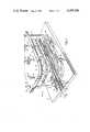
- FIG. 1is a partially schematic, partially idealized perspective view of an assembly apparatus for making decorative trim strip assemblies having laterally curved portions formed therein, and showing the relative unassembled relationship of the two major components of such assembly, namely an elongated polymeric resinous material strip element and a substantially rigid metallic backing plate;
- FIG. 2is a partial perspective view showing the elongated polymeric resinous material strip element assembled into a jig fixture shown in FIG. 1;
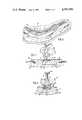
- FIG. 3is a cross-sectional area showing operative components of the apparatus of FIG. 1 as they are situated during the heating cycle of the assembly method according to this invention.
- FIG. 4is similar to FIG. 3 showing the operative components as they are situated during the cooling cycle of the assembly method according to this invention.
- this inventionprovides a decorative trim strip assembly having a laterally curved portion formed therein, where the decorative trim strip assembly comprises a substantially rigid metallic backing plate 12 and an elongated polymeric resinous material strip element 14.
- the metallic backing plate 12has a substantially planar face 16 (the underside of the backing plate 12 as shown in FIG. 1), and has a laterally curved portion 18 formed therein where the curve is to the desired configuration. As seen from FIG. 1, the backing plate 12 is laterally curved in the portion 18 in a plane which is parallel to the substantially planar face 16.
- the elongated polymeric resinous material strip element 14has substantially greater width than thickness, as indicated by the designations "W” and "T” in FIG. 1.
- the strip element 14has a substantially planar first surface 20, and the opposite surface 22 to the first surface 20 has a desired decorative appearance and surface contour.
- the decorative appearance and surface contour of the surface 22 of the plastic strip element 14may be such as is desired by the vehicle designer.
- At least one longitudinal slit 24is formed in the plastic strip element 14; and as will be seen hereafter, the longitudinal slit 24 is formed so as to be from a place 26 which is situated beyond a first end of the curved portion 18 which will be formed in the plastic strip when it is assembled to the backing plate 12.
- the longitudinal slit 24extends around the curve to the end of the strip element 14 which is remote from the first end of the curve 18 where the slit has started.
- FIG. 1an apparatus is shown in which the decorative strip assembly of the present invention is made, and within which the assembly method of the present invention is carried out.
- That apparatusdesignated generally at 30, has a fixed base plate 32 and a movable upper plate 34, which moves upwards and downwards along guide rods 36, two of which are shown.
- the driving force for the upper plate 34is transferred to it by such as a rod 38 secured to the drive cylinder (not shown).
- Electrodes 40Extending through the upper plate 38 and electrically insulated from it are electrodes 40, three of which are shown in the apparatus of FIG. 1, which number is generally sufficient for purposes of the present invention.
- the electrodes 40may conveniently be attached to a source of low voltage, high current electricity, such as a pair of series transformers or a centre-tape transformer, by wires 42 from the two outer electrodes and wire 44 from the inner electrode which goes to the centre tap or the common connection between the series transformers.
- a source of low voltage, high current electricitysuch as a pair of series transformers or a centre-tape transformer
- wires 42 from the two outer electrodes and wire 44 from the inner electrode which goes to the centre tap or the common connection between the series transformersmay be used, in keeping the ordinary skill
- cooling blocks 46Beneath the undersurface of the upper plate 34, there are located a number of cooling blocks 46.
- the exact number and spacing of the cooling blocks 46is determined by the size and configuration of the trim strip to be assembled; and in the embodiment shown, there are a number of gaps 48 between the cooling blocks 46 which accommodate the connector stems or tongs 50 formed in the backing plate 12.
- a jig fixture 52On the bottom plate 32, there is a jig fixture 52, which has formed in its upper face 54 the configuration of the lateral curve 18 which is desired for the decorative trim strip assembly being made, and the upper face of the jig fixture 52 is conveniently contoured in such a manner as to accommodate the surface contour 22 of the polymeric resinous material strip element 14.
- a number of hold-down elements 56are rotatably mounted above the bottom plate 32, on either side of the jig fixture 52, and conveniently have pins which extend into holes 58 formed in the bottom plate 32 for those purposes (shown in FIG. 2). Additionally, another hold-down element 60 is mounted on the bottom plate 32, on the inside of the curved portion 18 of the jig fixture 52.
- the rigid metallic backing plate 12is of lesser width that the polymeric resinous material strip element 14, (as shown in the drawings) but not necessarily so, and it may conveniently have a pair of edge flanges 62 which are formed and dimensioned so as to extend into a pair of recesses 64 formed longitudinally in the first surface 20 of the strip element 14.
- the strip element 14is assembled into the jig fixture 52 in such a manner that the contoured face 22 fits downward into the accommodating contoured portion of the jig fixture.
- the slit 24thus divides the strip element 14 into two portions, in this case, designated 14a and 14b; and the slit 24 extends from the first end of the curve at the point 26 to the end 66 of the strip element 14 which is beyond the curved portion remote from the first end thereof.
- the portion 14aextends somewhat beyond the end 66 of the portion 14b. Indeed, where a plurality of slits may be formed, each of the portions will extend to a differing amount beyond the curved portion 18.
- each of the portions 14a and 14b in the embodiment shown(and, in any event, all of the slit portions defined by the one or more longitudinal slits 24 formed in the strip element 14) is stressed to an extent in the area of the curvature 18 less than the amount of stress for such portion which is defined above as its stress resistance limit.
- the width of each longitudinal strip portion 14a and 14b in the region of the longitudinal slit 24 which extends from the point 26is such that the stress resistance of that respective longitudinal portion is not exceeded for the curvature thereof as defined by its relative position to the inside or outside of the curved portion 18 of the decorative trim strip being assembled.
- the preformed substantially rigid metallic backing plate 12is positioned over the jigged strip element 14.
- the edge flanges 62extend downwardly into the recesses 64 which are extruded in the surface 20 of the strip element 14.
- the strip elementis, of course, held in its place in the jig fixture 52 by the hold-down members 56 and 60, which extend over the outer edges of the surface 20 of the strip element 14 sufficiently to secure it in place, (see especially FIGS. 3 and 4).
- the electrodes 40are then lowered so that their lower ends contact the back or upper surface (in this case) of the backing plate 12, and the electric power is then turned on so that the backing plate 12 forms a resistance heating element in a circuit which comprises the electrodes and the backing plate 12 connected across the source of electric power.
- the electrodesmay be a carbon/nickel alloy, or any other low resistance element of the sort which may be readily available for purposes similar to the resistance heating purposes to which they are put in the present invention.
- the electrode 40are spring loaded by spring 70 so as to extend below the bottom surface of the cooling blocks 46.
- the spring 70compresses, thereby permitting the cooling blocks 46 to contact the backing plate 12, without damage to the electrodes 40 or the backing plate 12.
- the backing plate 12becomes hot due to its own electrical resistance, there is an induction heating of the polymeric resinous material strip element 14, due to the heat within the backing plate 12, so that a heat bonding of the material of the strip element 14 to the backing plate 12 may be achieved.
- the upper plate 34 with the cooling block 46is lowered so that the cooling block 46 contacts the upper or rear surface of the metallic backing plate 12, (see FIG. 4).
- the supply of electrical power to the electrodes 40is terminated.
- the cooling blocks 46have channels or tubes 68 formed in them through which a suitable cooling medium such as water may be pumped. A very rapid cooling of the metallic backing plate 12 and the polymeric resinous material strip element 14 which is, by now, heat bonded to the backing plate 12, is thereby assured.
- the assembled decorative trim strip assemblymay be such that the backing plate 12 and the elongated polymeric resinous material strip element 14 are bonded together other than by heat bonding.
- a suitable adhesive materialmay be placed on one or both of the contacting surfaces, which may be heat activated or pressure activated, so as to achieve the bond; and, indeed, if it is heat activated then the steps of the method according to the present invention would, in any event, be followed, as discussed above.
- the elongated polymeric resinous material strip elementis formed of extruded polyvinyl chloride material.
- the contoured face 22 of the strip element 14may have secured to it such other materials as a pre-printed vinyl or a metallized polyethylene teraphthalate.
- the material of the backing plate 12may be other than steel, in certain circumstances, providing that a bonding system--either adhesive or heat bonding--may be set up between the backing plate and the polymeric resinous material strip element.
- the backing plate 12is formed of steel, and as noted above, the polymeric resinous material is usually polyvinyl chloride.
- the slit 24--one or more of them--is placed across the width of the strip element 14 in any convenient place, and in any event is placed in such a position that the width of each longitudinal portion of the strip element 14 in the region of the slit is such that the stress resistance of each respective longitudinal portion is not exceeded for the curvature thereof in the curved portion of that respective longitudinal portion.
- the contoured and decorative surface 22 of the strip element 14is such that specific sections of it are delineated by discontinuities or reversals of curvature, or by transition from one form of decorative surface to another (such as from a metallized appearance to a woodgrain appearance)
- the longitudinal slit 24may conveniently be placed at such boundaries.
- trim stripwhich have been produced according to the present invention.
- An extruded polyvinyl chloride striphaving a cross section similar to that illustrated in FIGS. 3 and 4, was produced having an overall width of 1.020 inches, and the thickest dimension of the extruded polyvinyl chloride strip was 0.275 inches.
- the radius of curvature at the innermost edge of the assembled, laterally curved trim stripwas 2.750 inches.
Landscapes
- Engineering & Computer Science (AREA)
- Mechanical Engineering (AREA)
- Physics & Mathematics (AREA)
- Thermal Sciences (AREA)
- Extrusion Moulding Of Plastics Or The Like (AREA)
Abstract
Description
Claims (7)
Priority Applications (1)
| Application Number | Priority Date | Filing Date | Title |
|---|---|---|---|
| US06/366,227US4397896A (en) | 1981-02-10 | 1982-04-07 | Laterally curved decorative trim strip assembly and method of making same |
Applications Claiming Priority (2)
| Application Number | Priority Date | Filing Date | Title |
|---|---|---|---|
| US06/233,047US4364789A (en) | 1981-02-10 | 1981-02-10 | Method of making laterally curved decorative trim strip assembly |
| US06/366,227US4397896A (en) | 1981-02-10 | 1982-04-07 | Laterally curved decorative trim strip assembly and method of making same |
Related Parent Applications (1)
| Application Number | Title | Priority Date | Filing Date |
|---|---|---|---|
| US06/233,047DivisionUS4364789A (en) | 1981-02-10 | 1981-02-10 | Method of making laterally curved decorative trim strip assembly |
Publications (1)
| Publication Number | Publication Date |
|---|---|
| US4397896Atrue US4397896A (en) | 1983-08-09 |
Family
ID=26926590
Family Applications (1)
| Application Number | Title | Priority Date | Filing Date |
|---|---|---|---|
| US06/366,227Expired - LifetimeUS4397896A (en) | 1981-02-10 | 1982-04-07 | Laterally curved decorative trim strip assembly and method of making same |
Country Status (1)
| Country | Link |
|---|---|
| US (1) | US4397896A (en) |
Cited By (16)
| Publication number | Priority date | Publication date | Assignee | Title |
|---|---|---|---|---|
| US4636421A (en)* | 1986-02-27 | 1987-01-13 | Creation Windows, Inc. | Frame with decorative trim strip |
| US5143760A (en)* | 1990-06-27 | 1992-09-01 | The Standard Products Company | Extruded molding with desired contoured formation |
| US5350608A (en)* | 1993-04-13 | 1994-09-27 | The Standard Products Company | Decorative trim with one-piece plastic cover |
| FR2719249A1 (en)* | 1994-05-02 | 1995-11-03 | Cagnon Sa | Method of implanting metallic inserts in plastics |
| US5519972A (en)* | 1993-09-03 | 1996-05-28 | The Grigoleit Company | Decorative product having a decorative strip |
| US5525384A (en)* | 1995-01-12 | 1996-06-11 | Woodland Holding Corporation | Flexible molding strip having inserted decorative cord and furniture provided with such strips |
| US5639522A (en)* | 1994-07-25 | 1997-06-17 | Tokai Kogyo Co., Ltd. | Side protective moulding for automobiles |
| US20020108708A1 (en)* | 1997-12-31 | 2002-08-15 | Textron Systems Corporation | Metallized sheeting, composites, and methods for their formation |
| WO2010070474A3 (en)* | 2008-12-19 | 2010-09-02 | Flooring Industries Limited, Sarl | Coated panel comprising foam or polyvinyl chloride and method for manufacturing |
| US8925275B2 (en) | 2010-05-10 | 2015-01-06 | Flooring Industries Limited, Sarl | Floor panel |
| US9163414B2 (en) | 2010-05-10 | 2015-10-20 | Flooring Industries Limited, Sarl | Floor panel |
| US9200460B2 (en) | 2006-06-02 | 2015-12-01 | Flooring Industries Limited, Sarl | Floor covering, floor element and method for manufacturing floor elements |
| US9266382B2 (en) | 2008-12-19 | 2016-02-23 | Flooring Industries Limited, Sarl | Methods for manufacturing panels and panel obtained thereby |
| US9528278B2 (en) | 2009-12-22 | 2016-12-27 | Flooring Industries Limited, Sarl | Panel, covering and method for installing such panels |
| US10190323B2 (en) | 2010-05-10 | 2019-01-29 | Flooring Industries Limited, Sarl | Floor panel |
| US11794460B2 (en) | 2018-01-04 | 2023-10-24 | Flooring Industries Limited, Sarl | Methods for manufacturing panels |
Citations (2)
| Publication number | Priority date | Publication date | Assignee | Title |
|---|---|---|---|---|
| US3745056A (en)* | 1971-04-05 | 1973-07-10 | Standard Products Co | Trim strip structure |
| CA1020199A (en) | 1974-01-03 | 1977-11-01 | Theodore Loew | Composite plastic trim strip and method of making the same |
- 1982
- 1982-04-07USUS06/366,227patent/US4397896A/ennot_activeExpired - Lifetime
Patent Citations (2)
| Publication number | Priority date | Publication date | Assignee | Title |
|---|---|---|---|---|
| US3745056A (en)* | 1971-04-05 | 1973-07-10 | Standard Products Co | Trim strip structure |
| CA1020199A (en) | 1974-01-03 | 1977-11-01 | Theodore Loew | Composite plastic trim strip and method of making the same |
Cited By (80)
| Publication number | Priority date | Publication date | Assignee | Title |
|---|---|---|---|---|
| US4636421A (en)* | 1986-02-27 | 1987-01-13 | Creation Windows, Inc. | Frame with decorative trim strip |
| US5143760A (en)* | 1990-06-27 | 1992-09-01 | The Standard Products Company | Extruded molding with desired contoured formation |
| US5350608A (en)* | 1993-04-13 | 1994-09-27 | The Standard Products Company | Decorative trim with one-piece plastic cover |
| US5519972A (en)* | 1993-09-03 | 1996-05-28 | The Grigoleit Company | Decorative product having a decorative strip |
| FR2719249A1 (en)* | 1994-05-02 | 1995-11-03 | Cagnon Sa | Method of implanting metallic inserts in plastics |
| US5639522A (en)* | 1994-07-25 | 1997-06-17 | Tokai Kogyo Co., Ltd. | Side protective moulding for automobiles |
| US5525384A (en)* | 1995-01-12 | 1996-06-11 | Woodland Holding Corporation | Flexible molding strip having inserted decorative cord and furniture provided with such strips |
| US5688569A (en)* | 1995-01-12 | 1997-11-18 | Woodland Holding Corp. | Flexible molding strip having an inserted decorative cord and furniture provided with such strips |
| US20020108708A1 (en)* | 1997-12-31 | 2002-08-15 | Textron Systems Corporation | Metallized sheeting, composites, and methods for their formation |
| US6761793B2 (en)* | 1997-12-31 | 2004-07-13 | Textron Systems Corporation | Method for forming a metallized composite |
| US12385260B2 (en) | 2006-06-02 | 2025-08-12 | Unilin, Bv | Floor covering, floor element and method for manufacturing floor elements |
| US10975579B2 (en) | 2006-06-02 | 2021-04-13 | Flooring Industries Limited, Sarl | Floor covering, floor element and method for manufacturing floor elements |
| US9695599B2 (en) | 2006-06-02 | 2017-07-04 | Flooring Industries Limited, Sarl | Floor covering, floor element and method for manufacturing floor elements |
| US10358831B2 (en) | 2006-06-02 | 2019-07-23 | Flooring Industries Limited, Sarl | Floor covering, floor element and method for manufacturing floor elements |
| US11933055B2 (en) | 2006-06-02 | 2024-03-19 | Unilin, Bv | Floor covering, floor element and method for manufacturing floor elements |
| US9200460B2 (en) | 2006-06-02 | 2015-12-01 | Flooring Industries Limited, Sarl | Floor covering, floor element and method for manufacturing floor elements |
| US10745921B2 (en) | 2006-06-02 | 2020-08-18 | Flooring Industries Limited, Sarl | Floor covering, floor element and method for manufacturing floor elements |
| US10519674B2 (en) | 2006-06-02 | 2019-12-31 | Flooring Industries Limited, Sarl | Floor covering, floor element and method for manufacturing floor elements |
| US11680414B2 (en) | 2006-06-02 | 2023-06-20 | Flooring Industries Limited, Sarl | Floor covering, floor element and method for manufacturing floor elements |
| US9366037B2 (en) | 2006-06-02 | 2016-06-14 | Flooring Industries Limited, Sarl | Floor covering, floor element and method for manufacturing floor elements |
| US10975578B2 (en) | 2006-06-02 | 2021-04-13 | Flooring Industries Limited, Sarl | Floor covering, floor element and method for manufacturing floor elements |
| US9487957B2 (en) | 2006-06-02 | 2016-11-08 | Flooring Industries Limited, Sarl | Floor covering, floor element and method for manufacturing floor elements |
| US10125499B2 (en) | 2006-06-02 | 2018-11-13 | Flooring Industries Limited, Sarl | Floor covering, floor element and method for manufacturing floor elements |
| US9890542B2 (en) | 2006-06-02 | 2018-02-13 | Flooring Industries Limited, Sarl | Floor covering, floor element and method for manufacturing floor elements |
| US10017005B2 (en) | 2008-12-19 | 2018-07-10 | Flooring Industries Limited, Sarl | Coated panel and method for manufacturing such panel |
| EP3831615A1 (en)* | 2008-12-19 | 2021-06-09 | Flooring Industries Limited, SARL | Coated panel comprising foamable or foamed synthetic material |
| US11654712B2 (en) | 2008-12-19 | 2023-05-23 | Flooring Industries Limited, Sarl | Coated panel and method for manufacturing such panel |
| US11491816B2 (en) | 2008-12-19 | 2022-11-08 | Flooring Industries Limited, Sarl | Methods for manufacturing panels and panel obtained thereby |
| WO2010070474A3 (en)* | 2008-12-19 | 2010-09-02 | Flooring Industries Limited, Sarl | Coated panel comprising foam or polyvinyl chloride and method for manufacturing |
| EP3293016A1 (en)* | 2008-12-19 | 2018-03-14 | Flooring Industries Limited, SARL | Method for manufacturing a coated panel |
| RU2516900C2 (en)* | 2008-12-19 | 2014-05-20 | Флоринг Индастриз Лимитед, Сарл | Coated panel and method of its fabrication |
| US11198318B2 (en) | 2008-12-19 | 2021-12-14 | Flooring Industries Limited, Sarl | Methods for manufacturing panels and panel obtained thereby |
| US11059320B2 (en) | 2008-12-19 | 2021-07-13 | Flooring Industries Limited, Sarl | Coated panel and method for manufacturing such panel |
| US12251960B2 (en) | 2008-12-19 | 2025-03-18 | Unilin, Bv | Coated panel and method for manufacturing such panel |
| US9216610B2 (en) | 2008-12-19 | 2015-12-22 | Flooring Industries Limited, Sarl | Coated panel and method for manufacturing such panel |
| US9266382B2 (en) | 2008-12-19 | 2016-02-23 | Flooring Industries Limited, Sarl | Methods for manufacturing panels and panel obtained thereby |
| US11668099B2 (en) | 2009-12-22 | 2023-06-06 | Flooring Industries Limited, Sarl | Panel, covering and method for installing such panels |
| US9528278B2 (en) | 2009-12-22 | 2016-12-27 | Flooring Industries Limited, Sarl | Panel, covering and method for installing such panels |
| US10550582B2 (en) | 2009-12-22 | 2020-02-04 | Flooring Industries Limited, Sarl | Panel, covering and method for installing such panels |
| US9670683B2 (en) | 2009-12-22 | 2017-06-06 | Flooring Industries Limited,Sarl | Panel, covering and method for installing such panels |
| US10428534B2 (en) | 2009-12-22 | 2019-10-01 | Flooring Industries Limited, Sarl | Panel, covering and method for installing such panels |
| US9670682B2 (en) | 2009-12-22 | 2017-06-06 | Flooring Industries Limited, Sarl | Panel, covering and method for installing such panels |
| US10267048B2 (en) | 2010-05-10 | 2019-04-23 | Flooring Industries Limited, Sarl | Floor panel |
| US9809984B2 (en) | 2010-05-10 | 2017-11-07 | Flooring Industries Limited, Sarl | Floor panel |
| US10233655B2 (en) | 2010-05-10 | 2019-03-19 | Flooring Industries Limited, Sarl | Floor panel |
| US10597876B2 (en) | 2010-05-10 | 2020-03-24 | Flooring Industries Limited, Sarl | Floor panel |
| US10214921B2 (en) | 2010-05-10 | 2019-02-26 | Flooring Industries Limited, Sarl | Floor panel |
| US10815676B2 (en) | 2010-05-10 | 2020-10-27 | Flooring Industries Limited, Sarl | Floor panel |
| US10870994B2 (en) | 2010-05-10 | 2020-12-22 | Flooring Industries Limited Sarl | Floor panel |
| US10876303B2 (en) | 2010-05-10 | 2020-12-29 | Flooring Industries Limited, Sarl | Floor panel |
| US10889998B2 (en) | 2010-05-10 | 2021-01-12 | Flooring Industries Limited, Sarl | Floor panel |
| US10927553B2 (en) | 2010-05-10 | 2021-02-23 | Flooring Industries Limited, Sarl | Floor panel |
| US10208490B2 (en) | 2010-05-10 | 2019-02-19 | Flooring Industries Limited, Sarl | Floor panel |
| US10190323B2 (en) | 2010-05-10 | 2019-01-29 | Flooring Industries Limited, Sarl | Floor panel |
| US10100533B2 (en) | 2010-05-10 | 2018-10-16 | Flooring Industries Limited, Sarl | Floor panel |
| US10094123B2 (en) | 2010-05-10 | 2018-10-09 | Flooring Industries Limited, Sarl | Floor panel |
| US11193282B2 (en) | 2010-05-10 | 2021-12-07 | Flooring Industries Limited, Sarl | Floor panel |
| US10041259B2 (en) | 2010-05-10 | 2018-08-07 | Flooring Industries Limited, Sarl | Floor panel |
| US11236514B2 (en) | 2010-05-10 | 2022-02-01 | Flooring Industries Limited, Sarl | Floor panel |
| US11371249B2 (en) | 2010-05-10 | 2022-06-28 | Flooring Industries Limited, Sarl | Floor panel |
| US11377857B2 (en) | 2010-05-10 | 2022-07-05 | Flooring Industries Limited, Sarl | Floor panel |
| US10301831B2 (en) | 2010-05-10 | 2019-05-28 | Flooring Industries Limited, Sarl | Floor panel |
| US11505949B2 (en) | 2010-05-10 | 2022-11-22 | Flooring Industries Limited, Sarl | Floor panel |
| US11566432B2 (en) | 2010-05-10 | 2023-01-31 | Flooring Industries Limited, Sarl | Floor panel |
| US11634914B2 (en) | 2010-05-10 | 2023-04-25 | Flooring Industries Limited, Sarl | Floor panel |
| US11634913B2 (en) | 2010-05-10 | 2023-04-25 | Flooring Industries Limited, Sarl | Floor panel |
| US9783995B2 (en) | 2010-05-10 | 2017-10-10 | Flooring Industries Limited, Sarl | Floor panel |
| US9453348B1 (en) | 2010-05-10 | 2016-09-27 | Flooring Industries Limited, Sarl | Floor panel |
| US9366035B2 (en) | 2010-05-10 | 2016-06-14 | Flooring Industries Limited, Sarl | Floor panel |
| US11795702B2 (en) | 2010-05-10 | 2023-10-24 | Flooring Industries Limited Sarl | Floor panel |
| US8925275B2 (en) | 2010-05-10 | 2015-01-06 | Flooring Industries Limited, Sarl | Floor panel |
| US9163414B2 (en) | 2010-05-10 | 2015-10-20 | Flooring Industries Limited, Sarl | Floor panel |
| US11976471B2 (en) | 2010-05-10 | 2024-05-07 | Unilin Bv | Floor panel |
| US12012764B2 (en) | 2010-05-10 | 2024-06-18 | Unilin Bv | Floor panel |
| US12031337B2 (en) | 2010-05-10 | 2024-07-09 | Unilin, Bv | Floor panel |
| US12123201B2 (en) | 2010-05-10 | 2024-10-22 | Unilin, Bv | Floor panel |
| US12180719B2 (en) | 2010-05-10 | 2024-12-31 | Unilin Bv | Floor panel |
| US9080330B2 (en) | 2010-05-10 | 2015-07-14 | Flooring Industries Limited, Sarl | Floor panel |
| US12251916B2 (en) | 2018-01-04 | 2025-03-18 | Unilin, Bv | Methods for manufacturing panels |
| US11794460B2 (en) | 2018-01-04 | 2023-10-24 | Flooring Industries Limited, Sarl | Methods for manufacturing panels |
Similar Documents
| Publication | Publication Date | Title |
|---|---|---|
| US4397896A (en) | Laterally curved decorative trim strip assembly and method of making same | |
| US3947618A (en) | Electrically heated transparent panel | |
| US4364789A (en) | Method of making laterally curved decorative trim strip assembly | |
| RU2299808C2 (en) | Method of production of the plastic window glass with the electroconductive structure and the plastic window glass with the built-in wires | |
| EP0371810B1 (en) | Window for automobiles or the like, and method of manufacturing the same | |
| US4488033A (en) | Heater assembly for heating glass surface | |
| US3543465A (en) | Exterior molding structure | |
| US4635420A (en) | Motor vehicle glazing assembly and method of manufacture thereof | |
| KR960017225A (en) | Automotive interior parts and manufacturing method | |
| FR2486873B1 (en) | ||
| US4320286A (en) | Heater element | |
| US5520765A (en) | Method of manufacturing a hollow molding | |
| US5552195A (en) | Trim strip and method for making same | |
| CA2227822C (en) | Bodyside molding with bright insert and method of making same | |
| GB2168289A (en) | Laminated windows for vehicles | |
| PT1446985E (en) | Three-dimensional electroluminescence display | |
| US3778898A (en) | Method of making a laminated electrically heated window | |
| ES8303192A1 (en) | Molding laminate | |
| US5132162A (en) | Heated glazing | |
| EP0368441A2 (en) | Trim moulding for vehicles | |
| CA1164025A (en) | Laterally curved decorative trim strip assembly and method of making same | |
| US4384401A (en) | Method for forming a heater element | |
| JPS6341121A (en) | Manufacture of interior molding | |
| EP0079973B1 (en) | Extrusion/injection molding of trimmed product | |
| EP0452533B1 (en) | Arrangement of one or more connection plates for an electric heating element, which is secured on the inner side of a film-coated covering fabric, and securely fixed by welding or bonding with a supplementary sheet |
Legal Events
| Date | Code | Title | Description |
|---|---|---|---|
| STCF | Information on status: patent grant | Free format text:PATENTED CASE | |
| AS | Assignment | Owner name:STANDARD PRODUCTS (CANADA) LIMITED, 1030 ERIE ST., Free format text:ASSIGNMENT OF ASSIGNORS INTEREST.;ASSIGNOR:P.V. TRIM LIMITED;REEL/FRAME:004455/0064 Effective date:19850806 | |
| MAFP | Maintenance fee payment | Free format text:PAYMENT OF MAINTENANCE FEE, 4TH YEAR, PL 96-517 (ORIGINAL EVENT CODE: M170); ENTITY STATUS OF PATENT OWNER: LARGE ENTITY Year of fee payment:4 | |
| FEPP | Fee payment procedure | Free format text:MAINTENANCE FEE REMINDER MAILED (ORIGINAL EVENT CODE: REM.); ENTITY STATUS OF PATENT OWNER: LARGE ENTITY | |
| FEPP | Fee payment procedure | Free format text:SURCHARGE FOR LATE PAYMENT, PL 96-517 (ORIGINAL EVENT CODE: M176); ENTITY STATUS OF PATENT OWNER: LARGE ENTITY | |
| MAFP | Maintenance fee payment | Free format text:PAYMENT OF MAINTENANCE FEE, 8TH YEAR, PL 96-517 (ORIGINAL EVENT CODE: M171); ENTITY STATUS OF PATENT OWNER: LARGE ENTITY Year of fee payment:8 | |
| MAFP | Maintenance fee payment | Free format text:PAYMENT OF MAINTENANCE FEE, 12TH YEAR, LARGE ENTITY (ORIGINAL EVENT CODE: M185); ENTITY STATUS OF PATENT OWNER: LARGE ENTITY Year of fee payment:12 | |
| FEPP | Fee payment procedure | Free format text:PAT HLDR NO LONGER CLAIMS SMALL ENT STAT AS SMALL BUSINESS (ORIGINAL EVENT CODE: LSM2); ENTITY STATUS OF PATENT OWNER: LARGE ENTITY |