US4397648A - Drop sensing unit and associated drip chamber for IV fluid administration - Google Patents
Drop sensing unit and associated drip chamber for IV fluid administrationDownload PDFInfo
- Publication number
- US4397648A US4397648AUS06/204,771US20477180AUS4397648AUS 4397648 AUS4397648 AUS 4397648AUS 20477180 AUS20477180 AUS 20477180AUS 4397648 AUS4397648 AUS 4397648A
- Authority
- US
- United States
- Prior art keywords
- drip chamber
- drop
- sensing unit
- chamber
- housing
- Prior art date
- Legal status (The legal status is an assumption and is not a legal conclusion. Google has not performed a legal analysis and makes no representation as to the accuracy of the status listed.)
- Ceased
Links
- 239000012530fluidSubstances0.000titleclaimsabstractdescription14
- 238000009434installationMethods0.000claimsabstractdescription10
- 230000014759maintenance of locationEffects0.000claimsabstractdescription5
- 230000000087stabilizing effectEffects0.000claimsdescription9
- 238000012544monitoring processMethods0.000claimsdescription7
- 230000000452restraining effectEffects0.000claims2
- 230000000694effectsEffects0.000claims1
- 239000003978infusion fluidSubstances0.000claims1
- 230000003287optical effectEffects0.000description3
- 238000000034methodMethods0.000description2
- 230000002411adverseEffects0.000description1
- 238000004891communicationMethods0.000description1
- 230000003750conditioning effectEffects0.000description1
- 238000013461designMethods0.000description1
- 230000005484gravityEffects0.000description1
- 238000001990intravenous administrationMethods0.000description1
- 238000004519manufacturing processMethods0.000description1
- 239000000463materialSubstances0.000description1
- 230000013011matingEffects0.000description1
- 238000012986modificationMethods0.000description1
- 230000004048modificationEffects0.000description1
- 230000001737promoting effectEffects0.000description1
- 238000005086pumpingMethods0.000description1
Images

Classifications
- A—HUMAN NECESSITIES
- A61—MEDICAL OR VETERINARY SCIENCE; HYGIENE
- A61M—DEVICES FOR INTRODUCING MEDIA INTO, OR ONTO, THE BODY; DEVICES FOR TRANSDUCING BODY MEDIA OR FOR TAKING MEDIA FROM THE BODY; DEVICES FOR PRODUCING OR ENDING SLEEP OR STUPOR
- A61M5/00—Devices for bringing media into the body in a subcutaneous, intra-vascular or intramuscular way; Accessories therefor, e.g. filling or cleaning devices, arm-rests
- A61M5/14—Infusion devices, e.g. infusing by gravity; Blood infusion; Accessories therefor
- A61M5/168—Means for controlling media flow to the body or for metering media to the body, e.g. drip meters, counters ; Monitoring media flow to the body
- A61M5/16886—Means for controlling media flow to the body or for metering media to the body, e.g. drip meters, counters ; Monitoring media flow to the body for measuring fluid flow rate, i.e. flowmeters
- A61M5/1689—Drip counters
- Y—GENERAL TAGGING OF NEW TECHNOLOGICAL DEVELOPMENTS; GENERAL TAGGING OF CROSS-SECTIONAL TECHNOLOGIES SPANNING OVER SEVERAL SECTIONS OF THE IPC; TECHNICAL SUBJECTS COVERED BY FORMER USPC CROSS-REFERENCE ART COLLECTIONS [XRACs] AND DIGESTS
- Y10—TECHNICAL SUBJECTS COVERED BY FORMER USPC
- Y10S—TECHNICAL SUBJECTS COVERED BY FORMER USPC CROSS-REFERENCE ART COLLECTIONS [XRACs] AND DIGESTS
- Y10S128/00—Surgery
- Y10S128/13—Infusion monitoring
Definitions
- IV administrationparenteral fluid administration
- IV drop sensing unitand dedicated or associated drip chamber for use in an IV fluid administration system whereby installation, retention and removal are enhanced and aid is afforded in preventing use of chambers with operating characteristics differing from those desired.
- IV fluid administrationhas conventionally involved use of a disposable fluid administration set with an elongated drip chamber. Discrete fluid drops fall from a drop former to a reservoir and may be observed or detected through a transparent wall as they fall through the chamber.
- One such systemprovides for directly setting the desired delivery rate in milliliters per hour and, in turn, monitors the drop rate via the sensing unit and compares it with the desired rate.
- the dropsare of a specified size, e.g., 60 drops per milliliter. Should the drop size differ, e.g., the drops be 20 drops per milliliter in size, performance clearly is adversely affected.
- volumetric systems of the type just describedthat there be minimal variation in drop size from set to set. This is a matter that is subject to control in a given manufacturing operation tailored to accomplish that result.
- sensing unitswith mounting elements that engage mating retention elements on a dedicated or associated set. This is for the purpose of positioning and preventing use of other than the associated set.
- sensing unitshave not been entirely effective in establishing and maintaining proper positioning.
- sensing unitshave been inconvenient to install and remove from the drip chamber of the dedicated or associated set.
- sensing unitshould desirably aid in preventing use on any drip chamber other than the specially designed and manufactured item.
- a further attribute desiredis that the sensing unit be adapted for each installation and removal.
- the present inventionsolves the need that exists and resides in an improved drop sensing unit and dedicated or associated drip chamber.
- Retaining means on the chamber and sensing unitprovide for positive and proper positioning of the elements relative to one another in an automatic self-aligning action, yet enable the sensing unit to be conveniently installed on and removed from the chamber.
- the retaining meansincorporate engaging means selectively movable toward and away from one another during installation and removal. The range of movement of such engaging means is limited, and in this manner the sensing unit is adapted to aid in preventing use of drip chambers other than those of the dedicated or associated design.
- the desired operating characteristicsare achieved by having the engaging means at oppositely disposed and vertically spaced locations relative to the vertically oriented chamber. This arrangement is advantageous with respect to positioning and restrains the sensing unit relative to the chamber. Additionally, it facilitates the installation and removal of the sensing unit.
- cantilevered projections adjacent the upper end of the drip chamber and cooperating latching and stabilizing posts on the sensing unit, and conforming contact surfaces on the sensing unit and chambertogether comprise the engaging means.
- the support and stabilizing postscontact the projections as the sensing unit is spring actuated to a closed position to urge the sensing unit and chamber into the desired relative position.
- the conforming surfaces on the sensing unit and wall of the chambermake contact at a location vertically spaced from the projections and restrain the drip chamber against both relative vertical and lateral movement.
- the extent of actuating movement of elements of the sensing unitis limited so as to provide for positioning engagement only on one of the projections adjacent its terminal end and on the chamber at the vertically spaced location. This limit of travel excludes a clamping action being applied directly to the wall of the chamber on both sides thereof. In this manner, the sensing unit aids in preventing use of nondedicated sets.
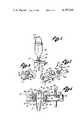
- FIG. 1is a perspective view of a dedicated drip chamber and sensing unit embodying the invention installed in an IV administration system.
- FIG. 2is a perspective view on an enlarged scale of the sensing unit.
- FIG. 3is an enlarged fragmentary perspective view of a portion of the sensing unit taken in the direction of the arrowed line 3 in FIG. 2.
- FIG. 4is an elevational view, with certain parts shown in longitudinal section, of the drip chamber and sensing unit in operable relation.
- FIG. 5is an elevational view of the sensing unit in the initial stage of installation on the drip chamber.
- FIG. 6is an elevational view of the sensing unit at a further stage of installation (phantom lines) and finally installed (solid lines) on the drip chamber.
- FIG. 7is an elevational view taken along the line 7--7 in FIG. 5, with certain portions being shown in section.
- FIG. 8is a fragmentary sectional view of the contact between the wing and the latch post taken along line 8--8 in FIG. 6.
- the presently preferred embodiment of the inventionincludes a dedicated or associated disposable drip chamber 12 and a specially designed, reusable sensing unit 13 actuable for installation on or removal from the drip chamber 12.
- This assemblyis intended for use as a component part of a solution administration system 16 wherein a bottle 18 suspended from a hook 20 feeds the dripping of fluid through the drip chamber 12 into a delivery tube 22.
- the electronic signalsinitiated in the sensing unit 13 as each drop breaks a light beam, are transmitted to electronic signal conditioning, counting, and integrating means (not shown) through signal cable 24 to allow remote and automatic monitoring of solution administration.
- the drip chamber 12is provided with a generally elliptically shaped cantilever wing 14 mounted at the upper end 44 of the drip chamber 12.
- the photoelectric sensing meansis contained within the body of the sensing unit 13, and for proper operation the photoelectric sensing means must be mounted so that the optical path 94 is normal to the drip chamber cylindrical axis 26 at a fixed distance below the cantilever wing 14.
- the first housing section 30is provided with a conforming surface 28 (FIG. 2) having proper curvature for conforming to the lateral cylindrical surface 11 of drip chamber 12. This conforming surface 28 is vertically spaced from cantilever wing 14 along the drip chamber cylindrical axis 26.
- a stabilizing post 32is mounted on the first housing section 30 so that it may be placed in contact with and rest against the underside of the cantilever wing 14.
- a latch post 34 presenting an inclined plane 68 to cantilever wing 14is mounted to a sleeve 36 slidably mounted over a second housing section 38. The latch post 34 may be engaged to the cantilever wing 14 by retracting the sleeve 36 and then urging the sleeve forward by spring biasing action until contact is achieved.
- the drip chamber 12 for delivering fluid from bottle 18 to delivery tube 22is generally of hollow tubular form and consists of a cylindrical portion 40 joined to a lower conical portion 42 whose small end 46 is suitable for receiving delivery tube 22. Near the uper end 44 and lying substantially on the drip chamber cylindrical axis 26 of the cylindrical portion 40 is located a drop former 48.
- the drop former 48is a precision hollow tube which emits drops of fluid at a precise size determined by its dimensions.
- the drip chamber 12thereby serves as a precision metering device in the solution administration system 16.
- the drip chamber 12is provided with a plurality of cantilever projections oppositely disposed in pairs across a diameter of the cylindrical portion 40.
- the cantilever wing 14defines a pair of projections firmly attached transversely to the drip chamber cylindrical axis 26 near the upper end 44 of the cylindrical portion 42.
- the cantilever wing 14is substantially flat and of generally elliptical shape, preferably formed of a single piece of plastic or like material.
- the shape of the end portion 50 found at either elongated end of the cantilever wing 14is suitably narrowed to mate with the latch post 34, allowing attachment of the sensing unit 13.
- the cantilever wing 14is symmetrical about its shorter axis, thereby allowing the latch post 34 to be mated with either narrow end portion 50.
- the sensing unit 13generally comprises a tubular housing with a central sensing gap 52 for receiving the drip chamber 12.
- the tubular housingincludes a first housing section 30 containing the light source 53 and a second housing section 38 containing the photocell 54 and supporting the sleeve 36.
- the two sections 30 and 38are supported in fixed coaxial relation by a hollow external bridging member 56.
- Hollow bridging member 56allows electrical communication between sections 30 and 38.
- the first housing section 30provides two of the contact surfaces for orienting the sensing unit 13 properly in relation to the drip chamber 12.
- a conforming surface 28 on the portion of the first housing section 30 adjacent the sensing gap 52is adapted to contact the lateral cylindrical surface 11 of drip chamber 12.
- the stabilizing post 32is adapted to contact and rest against the lower side of the cantilever wing 14 at the stabilizing post contact surface 58.
- the light source 53is located in a first cavity 60 within the first housing section 30.
- Second housing section 38contains a second cavity 88 for receiving photocell 54.
- Section 38also supports spring-biased sleeve 36.
- Sleeve 36is biased toward the sensing gap 52 by spring 78 carried within the second housing section 38.
- the limit of movement of sleeve 36is defined by the motion of rod 80 in slot 82.
- the length of bridging member 56is chosen so that the minimum spacing along the optical path 94 between facing end 90 of sleeve 36 and facing end 92 of first housing section 30 is substantially larger than the diameter of cylindrical portion 40, so that sensing unit 13 may not be clamped directly using both facing ends 90 and 92 to the lateral cylindrical surface 11.
- Rod 80also conveniently supports a pair of finger grip rods 84 mounted radially outward from opposite sides of sleeve 36. In conjunction with the enlarged outer sealed end 86 the rods 84 form a syringe-type grip familiar to medical personnel for selectively retracting the sleeve to enable mounting or removal of sensing unit 13.
- Sleeve 36carries a latch post 34 adapted for engaging the end portion 50 of cantilever wing 14.
- Latch post 34includes side members 62 and 64 and a top member 66.
- the side members 62 and 64define an inclined plane surface 68.
- the inclined edges 70 and 72 of the side members 62 and 64have bevel surfaces 74 and 76 to generally conform to the curvature of the end portion 50 (FIG. 8) thereby promoting a camming action of movement of end portion 50 into proper contact with top member 66 during attachment procedures.
- sensing unit 13Attachment of sensing unit 13 to drip chamber 12 is accomplished as shown in the sequence FIG. 5, FIG. 6 and FIG. 4.
- Sleeve 36is first retracted by compressing spring 78 through opposing pressure on rods 84 and sealed end 86.
- Sensing unit 13is moved into its approximate position with drip chamber 12 lying generally within sensing gap 52. This approximate positioning may be accomplished by moving sensing unit 13 generally along a radius of cylindrical portion 40 rather than parallel to the drip chamber cylindrical axis 26. This ability to introduce the sensing unit 13 from the side using only a single hand rather than from below represents a significant convenience feature for hospital personnel.
- end portion 50Upon gradual releasing of tension in spring 78, end portion 50 will be spring biased into position for engaging latch post 34 by a cam action along inclined edges 70 and 72.
- the drip chamber 12is urged into its proper aligned position with the self-aligning action produced by movement of sleeve 36.
- the lateral cylindrical surface 11 of drip chamber 12achieves full contact with conforming surface 28, stabilizing post 32 contacts the underside of cantilever wing 14 along contact surface 58 and end portion 50 completes engagement of latch post 34 by contacting the lower side of top member 66.
- Sensing unit 13is then securely but removably held to drip chamber 12 so that optical path 94 is substantially normal to the cylindrical axis 26 and at a fixed axial location.
- sensing unit 13cannot be directly clamped on a drip chamber having no cantilever wing 14 or functional equivalent. If an attempt is made to mount sensing unit 13 on such an improper drip chamber, the loose fit will result in sensing unit 13 falling away from the drip chamber of otherwise indicating the error to an attendant, thereby aiding in preventing use of an improper set.
- a sensing unitmay be securely mounted to a drip chamber in the proper operating position easily and securely using only one hand. Additionally, the cooperating arrangement of projections on the drip chamber and the described latching mechanism on the drop sensor aid in preventing use of the drop sensor with any drip chamber for which it is not specifically designed.
Landscapes
- Health & Medical Sciences (AREA)
- Biomedical Technology (AREA)
- Hematology (AREA)
- Vascular Medicine (AREA)
- Engineering & Computer Science (AREA)
- Anesthesiology (AREA)
- Physics & Mathematics (AREA)
- Heart & Thoracic Surgery (AREA)
- Fluid Mechanics (AREA)
- Life Sciences & Earth Sciences (AREA)
- Animal Behavior & Ethology (AREA)
- General Health & Medical Sciences (AREA)
- Public Health (AREA)
- Veterinary Medicine (AREA)
- Infusion, Injection, And Reservoir Apparatuses (AREA)
Abstract
Description
Claims (14)
Priority Applications (7)
| Application Number | Priority Date | Filing Date | Title |
|---|---|---|---|
| US06/204,771US4397648A (en) | 1980-11-07 | 1980-11-07 | Drop sensing unit and associated drip chamber for IV fluid administration |
| PCT/US1981/001483WO1982001653A1 (en) | 1980-11-07 | 1981-11-03 | Drops sensing unit and associated drip chamber for iv fluid administration |
| DE8282900057TDE3176627D1 (en) | 1980-11-07 | 1981-11-03 | Drops sensing unit and associated drip chamber for iv fluid administration |
| JP57500062AJPH0416186B2 (en) | 1980-11-07 | 1981-11-03 | |
| EP82900057AEP0064548B1 (en) | 1980-11-07 | 1981-11-03 | Drops sensing unit and associated drip chamber for iv fluid administration |
| CA000389395ACA1164756A (en) | 1980-11-07 | 1981-11-04 | Drop sensing unit and associated drip chamber for iv fluid administration |
| US06/762,051USRE32294E (en) | 1980-11-07 | 1985-08-02 | Drop sensing unit and associated drip chamber for IV fluid administration |
Applications Claiming Priority (1)
| Application Number | Priority Date | Filing Date | Title |
|---|---|---|---|
| US06/204,771US4397648A (en) | 1980-11-07 | 1980-11-07 | Drop sensing unit and associated drip chamber for IV fluid administration |
Related Child Applications (1)
| Application Number | Title | Priority Date | Filing Date |
|---|---|---|---|
| US06/762,051ReissueUSRE32294E (en) | 1980-11-07 | 1985-08-02 | Drop sensing unit and associated drip chamber for IV fluid administration |
Publications (1)
| Publication Number | Publication Date |
|---|---|
| US4397648Atrue US4397648A (en) | 1983-08-09 |
Family
ID=22759372
Family Applications (2)
| Application Number | Title | Priority Date | Filing Date |
|---|---|---|---|
| US06/204,771CeasedUS4397648A (en) | 1980-11-07 | 1980-11-07 | Drop sensing unit and associated drip chamber for IV fluid administration |
| US06/762,051Expired - LifetimeUSRE32294E (en) | 1980-11-07 | 1985-08-02 | Drop sensing unit and associated drip chamber for IV fluid administration |
Family Applications After (1)
| Application Number | Title | Priority Date | Filing Date |
|---|---|---|---|
| US06/762,051Expired - LifetimeUSRE32294E (en) | 1980-11-07 | 1985-08-02 | Drop sensing unit and associated drip chamber for IV fluid administration |
Country Status (6)
| Country | Link |
|---|---|
| US (2) | US4397648A (en) |
| EP (1) | EP0064548B1 (en) |
| JP (1) | JPH0416186B2 (en) |
| CA (1) | CA1164756A (en) |
| DE (1) | DE3176627D1 (en) |
| WO (1) | WO1982001653A1 (en) |
Cited By (45)
| Publication number | Priority date | Publication date | Assignee | Title |
|---|---|---|---|---|
| USD273419S (en) | 1981-11-30 | 1984-04-10 | Abbott Laboratories | Flow detector for an intravenous administration set |
| US4496351A (en)* | 1982-04-05 | 1985-01-29 | Ipco Corporation | Infusion monitor |
| USD278743S (en) | 1982-06-28 | 1985-05-07 | Ivac Corporation | Parenteral infusion pump |
| EP0199919A1 (en)* | 1985-03-06 | 1986-11-05 | Ivac Corporation | Optical flow sensor |
| US4668216A (en)* | 1985-03-11 | 1987-05-26 | Ivac Corporation | System for mounting a drop sensor to a drip chamber |
| US4681569A (en)* | 1985-03-22 | 1987-07-21 | Coble Stephen J | IV rate meter |
| USD291353S (en) | 1985-02-04 | 1987-08-11 | Ivac Corporation | Flow sensor for IV fluid administration |
| USD292610S (en) | 1985-03-21 | 1987-11-03 | Invivo Research Laboratories, Inc. | IV fluid flow rate meter |
| WO1987007161A1 (en)* | 1986-05-28 | 1987-12-03 | Kamen Dean L | Drop detection housing with positive tactile signaling |
| US4775368A (en)* | 1986-02-19 | 1988-10-04 | Pfrimmer-Viggo Gmbh & Co. Kg | Infusion device |
| US4834744A (en)* | 1987-11-04 | 1989-05-30 | Critikon, Inc. | Spike for parenteral solution container |
| USD311954S (en) | 1987-02-19 | 1990-11-06 | Dean Kamen | Drip chamber cap |
| US4986821A (en)* | 1986-05-28 | 1991-01-22 | Kamen Dean L | Drop detection housing with positive tactile signaling |
| USD314434S (en) | 1987-02-19 | 1991-02-05 | Dean Kamen | Drip chamber cap |
| US5002539A (en)* | 1987-04-08 | 1991-03-26 | Coble Stephen J | IV rate meter |
| US5045069A (en)* | 1989-01-17 | 1991-09-03 | Robert Imparato | Portable infusion monitor |
| WO1992006720A1 (en)* | 1990-10-22 | 1992-04-30 | Entracare Corporation | A medical fluid delivery system with uniquely configured pump unit and fluid delivery set |
| US5139482A (en)* | 1990-01-18 | 1992-08-18 | Simeon Paula S | Fluid infusion line monitor |
| US5186057A (en)* | 1991-10-21 | 1993-02-16 | Everhart Howard R | Multi-beam liquid-drop size/rate detector apparatus |
| US5575779A (en)* | 1994-12-30 | 1996-11-19 | Namic U.S.A. Corporation | Liquid regulator and method of use |
| USD383206S (en)* | 1990-10-22 | 1997-09-02 | Nutricare Medical Products, Inc. | Medical fluid drip container |
| WO2000048648A1 (en)* | 1997-07-10 | 2000-08-24 | Unisor Multisystems Ltd. | Drop monitoring unit for infusion sets |
| US6539248B1 (en) | 1993-07-14 | 2003-03-25 | Abbott Laboratories | Dye management system including an administration set with an in line burette |
| US6592126B2 (en)* | 2001-07-20 | 2003-07-15 | Flowserve Management Company | Mechanical seal leak detector |
| US6736801B1 (en) | 1998-02-18 | 2004-05-18 | George Gallagher | Method and apparatus for monitoring intravenous drips |
| US20050142013A1 (en)* | 2001-12-17 | 2005-06-30 | Faries Durward I.Jr. | Method and apparatus for heating solutions within intravenous lines to desired temperatures during infusion |
| US20080051732A1 (en)* | 2006-06-23 | 2008-02-28 | Thaiping Chen | Drop sensing device for monitoring intravenous fluid flow |
| US20080147016A1 (en)* | 1997-03-03 | 2008-06-19 | Faries Durward I | Method and Apparatus for Pressure Infusion and Temperature Control of Infused Liquids |
| US20080205481A1 (en)* | 2007-02-22 | 2008-08-28 | Faries Durward I | Method and Apparatus for Measurement and Control of Temperature for Infused Liquids |
| US20090143742A1 (en)* | 2007-07-17 | 2009-06-04 | C.R. Bard, Inc. | Securement system for a medical article |
| US20090247865A1 (en)* | 2004-04-16 | 2009-10-01 | Medrad, Inc. | Drip chamber and fluid level sensing mechanism for a fluid delivery system |
| US7740611B2 (en) | 2005-10-27 | 2010-06-22 | Patented Medical Solutions, Llc | Method and apparatus to indicate prior use of a medical item |
| US8487738B2 (en) | 2006-03-20 | 2013-07-16 | Medical Solutions, Inc. | Method and apparatus for securely storing medical items within a thermal treatment system |
| US8801656B2 (en) | 2012-10-29 | 2014-08-12 | Hospira, Inc. | Fluid flow passage to improve air-in-line detection |
| US8821011B2 (en) | 1999-03-30 | 2014-09-02 | Medical Solutions, Inc. | Method and apparatus for monitoring temperature of intravenously delivered fluids and other medical items |
| US8845586B2 (en) | 2004-03-09 | 2014-09-30 | Patented Medical Solutions Llc | Method and apparatus for facilitating injection of medication into an intravenous fluid line while maintaining sterility of infused fluids |
| US9119912B2 (en) | 2001-03-12 | 2015-09-01 | Medical Solutions, Inc. | Method and apparatus for controlling pressurized infusion and temperature of infused liquids |
| US9211381B2 (en) | 2012-01-20 | 2015-12-15 | Medical Solutions, Inc. | Method and apparatus for controlling temperature of medical liquids |
| US9656029B2 (en) | 2013-02-15 | 2017-05-23 | Medical Solutions, Inc. | Plural medical item warming system and method for warming a plurality of medical items to desired temperatures |
| US9737661B2 (en) | 2013-01-23 | 2017-08-22 | Tatsuta Electric Wire & Cable Co., Ltd. | Infusion speed measurement instrument |
| US10143795B2 (en) | 2014-08-18 | 2018-12-04 | Icu Medical, Inc. | Intravenous pole integrated power, control, and communication system and method for an infusion pump |
| US10918787B2 (en) | 2015-05-26 | 2021-02-16 | Icu Medical, Inc. | Disposable infusion fluid delivery device for programmable large volume drug delivery |
| USD939079S1 (en) | 2019-08-22 | 2021-12-21 | Icu Medical, Inc. | Infusion pump |
| US11213619B2 (en) | 2013-11-11 | 2022-01-04 | Icu Medical, Inc. | Thermal management system and method for medical devices |
| USD1052728S1 (en) | 2021-11-12 | 2024-11-26 | Icu Medical, Inc. | Medical fluid infusion pump |
Families Citing this family (27)
| Publication number | Priority date | Publication date | Assignee | Title |
|---|---|---|---|---|
| WO1991012834A1 (en)* | 1990-02-28 | 1991-09-05 | Kent Archibald G | Automatic iv clamp |
| US5154704A (en) | 1990-10-31 | 1992-10-13 | Kent Archibald G | IV clamp with tube clip |
| US5411052A (en)* | 1992-04-15 | 1995-05-02 | Fisher & Paykel Limited | Liquid supply apparatus |
| US5671736A (en)* | 1995-10-17 | 1997-09-30 | Graphic Controls Corporation | Fetal electrode product with easy-to-handle connector |
| US5843045A (en)* | 1997-01-17 | 1998-12-01 | Dupont; Frank Stuart | Infusion illuminator |
| US7255680B1 (en) | 1999-10-27 | 2007-08-14 | Cardinal Health 303, Inc. | Positive pressure infusion system having downstream resistance measurement capability |
| WO2011081585A1 (en)* | 2009-12-30 | 2011-07-07 | Svensson, Fredrik | Infusion control device |
| US9151646B2 (en) | 2011-12-21 | 2015-10-06 | Deka Products Limited Partnership | System, method, and apparatus for monitoring, regulating, or controlling fluid flow |
| US8531517B2 (en)* | 2010-07-15 | 2013-09-10 | Kai Tao | IV monitoring by video and image processing |
| US10488848B2 (en) | 2011-12-21 | 2019-11-26 | Deka Products Limited Partnership | System, method, and apparatus for monitoring, regulating, or controlling fluid flow |
| US9746093B2 (en) | 2011-12-21 | 2017-08-29 | Deka Products Limited Partnership | Flow meter and related system and apparatus |
| US9724466B2 (en) | 2011-12-21 | 2017-08-08 | Deka Products Limited Partnership | Flow meter |
| US9746094B2 (en) | 2011-12-21 | 2017-08-29 | Deka Products Limited Partnership | Flow meter having a background pattern with first and second portions |
| US10228683B2 (en) | 2011-12-21 | 2019-03-12 | Deka Products Limited Partnership | System, method, and apparatus for monitoring, regulating, or controlling fluid flow |
| US9435455B2 (en) | 2011-12-21 | 2016-09-06 | Deka Products Limited Partnership | System, method, and apparatus for monitoring, regulating, or controlling fluid flow |
| US9372486B2 (en) | 2011-12-21 | 2016-06-21 | Deka Products Limited Partnership | System, method, and apparatus for monitoring, regulating, or controlling fluid flow |
| US9759343B2 (en) | 2012-12-21 | 2017-09-12 | Deka Products Limited Partnership | Flow meter using a dynamic background image |
| USD752209S1 (en) | 2013-11-06 | 2016-03-22 | Deka Products Limited Partnership | Apparatus to control fluid flow through a tube |
| USD745661S1 (en) | 2013-11-06 | 2015-12-15 | Deka Products Limited Partnership | Apparatus to control fluid flow through a tube |
| USD751690S1 (en) | 2013-11-06 | 2016-03-15 | Deka Products Limited Partnership | Apparatus to control fluid flow through a tube |
| USD751689S1 (en) | 2013-11-06 | 2016-03-15 | Deka Products Limited Partnership | Apparatus to control fluid flow through a tube |
| USD749206S1 (en) | 2013-11-06 | 2016-02-09 | Deka Products Limited Partnership | Apparatus to control fluid flow through a tube |
| CN108697845B (en) | 2016-01-28 | 2021-09-17 | 德卡产品有限公司 | Apparatus for monitoring, regulating or controlling fluid flow |
| USD905848S1 (en) | 2016-01-28 | 2020-12-22 | Deka Products Limited Partnership | Apparatus to control fluid flow through a tube |
| USD854145S1 (en) | 2016-05-25 | 2019-07-16 | Deka Products Limited Partnership | Apparatus to control fluid flow through a tube |
| WO2021021596A1 (en) | 2019-07-26 | 2021-02-04 | Deka Products Limited Partnership | Apparatus for monitoring, regulating, or controlling fluid flow |
| USD964563S1 (en) | 2019-07-26 | 2022-09-20 | Deka Products Limited Partnership | Medical flow clamp |
Citations (6)
| Publication number | Priority date | Publication date | Assignee | Title |
|---|---|---|---|---|
| US3500366A (en)* | 1966-10-03 | 1970-03-10 | Gen Instrument Corp | Monitoring system for fluid flow in drop form |
| US3596515A (en)* | 1967-11-27 | 1971-08-03 | Ivac Corp | Drop flow sensor and resilient clamp therefor |
| US4038981A (en)* | 1974-07-26 | 1977-08-02 | Burron Medical Products, Inc. | Electronically controlled intravenous infusion set |
| US4038982A (en)* | 1975-12-03 | 1977-08-02 | Burron Medical Products, Inc. | Electrically controlled intravenous infusion set |
| US4321461A (en)* | 1980-04-18 | 1982-03-23 | K/W/D Associates | Flow rate monitor and totalizer with count display |
| US4346606A (en)* | 1980-03-10 | 1982-08-31 | Imed Corporation | Rate meter |
Family Cites Families (7)
| Publication number | Priority date | Publication date | Assignee | Title |
|---|---|---|---|---|
| US3428393A (en)* | 1965-11-05 | 1969-02-18 | Roger Lannes De Montebello | Optical dissector |
| US3449952A (en)* | 1967-05-19 | 1969-06-17 | Amp Inc | Drop-count attachment |
| US3462213A (en)* | 1968-08-26 | 1969-08-19 | Roger Lannes De Montebello | Three-dimensional optical display apparatus |
| GB1458926A (en)* | 1974-06-18 | 1976-12-15 | Denner J R | Cameras and enlargers |
| CH585069A5 (en)* | 1974-07-05 | 1977-02-28 | Wuilleret Bernard | Plastic dropper bottle as medical sample tube - has a stopper at one end, and a cap over the dropper at the other |
| JPS5127131A (en)* | 1974-08-30 | 1976-03-06 | Hitachi Ltd | |
| JPS5158950A (en)* | 1974-11-20 | 1976-05-22 | Tokyo Shibaura Electric Co | FUIRUMUSOZOSOCHI |
- 1980
- 1980-11-07USUS06/204,771patent/US4397648A/ennot_activeCeased
- 1981
- 1981-11-03DEDE8282900057Tpatent/DE3176627D1/ennot_activeExpired
- 1981-11-03WOPCT/US1981/001483patent/WO1982001653A1/enactiveIP Right Grant
- 1981-11-03JPJP57500062Apatent/JPH0416186B2/janot_activeExpired - Lifetime
- 1981-11-03EPEP82900057Apatent/EP0064548B1/ennot_activeExpired
- 1981-11-04CACA000389395Apatent/CA1164756A/ennot_activeExpired
- 1985
- 1985-08-02USUS06/762,051patent/USRE32294E/ennot_activeExpired - Lifetime
Patent Citations (6)
| Publication number | Priority date | Publication date | Assignee | Title |
|---|---|---|---|---|
| US3500366A (en)* | 1966-10-03 | 1970-03-10 | Gen Instrument Corp | Monitoring system for fluid flow in drop form |
| US3596515A (en)* | 1967-11-27 | 1971-08-03 | Ivac Corp | Drop flow sensor and resilient clamp therefor |
| US4038981A (en)* | 1974-07-26 | 1977-08-02 | Burron Medical Products, Inc. | Electronically controlled intravenous infusion set |
| US4038982A (en)* | 1975-12-03 | 1977-08-02 | Burron Medical Products, Inc. | Electrically controlled intravenous infusion set |
| US4346606A (en)* | 1980-03-10 | 1982-08-31 | Imed Corporation | Rate meter |
| US4321461A (en)* | 1980-04-18 | 1982-03-23 | K/W/D Associates | Flow rate monitor and totalizer with count display |
Cited By (63)
| Publication number | Priority date | Publication date | Assignee | Title |
|---|---|---|---|---|
| USD273419S (en) | 1981-11-30 | 1984-04-10 | Abbott Laboratories | Flow detector for an intravenous administration set |
| US4496351A (en)* | 1982-04-05 | 1985-01-29 | Ipco Corporation | Infusion monitor |
| USD278743S (en) | 1982-06-28 | 1985-05-07 | Ivac Corporation | Parenteral infusion pump |
| USD291353S (en) | 1985-02-04 | 1987-08-11 | Ivac Corporation | Flow sensor for IV fluid administration |
| EP0199919A1 (en)* | 1985-03-06 | 1986-11-05 | Ivac Corporation | Optical flow sensor |
| US4680977A (en)* | 1985-03-06 | 1987-07-21 | Ivac Corporation | Optical flow sensor |
| US4668216A (en)* | 1985-03-11 | 1987-05-26 | Ivac Corporation | System for mounting a drop sensor to a drip chamber |
| USD292610S (en) | 1985-03-21 | 1987-11-03 | Invivo Research Laboratories, Inc. | IV fluid flow rate meter |
| US4681569A (en)* | 1985-03-22 | 1987-07-21 | Coble Stephen J | IV rate meter |
| US4775368A (en)* | 1986-02-19 | 1988-10-04 | Pfrimmer-Viggo Gmbh & Co. Kg | Infusion device |
| WO1987007161A1 (en)* | 1986-05-28 | 1987-12-03 | Kamen Dean L | Drop detection housing with positive tactile signaling |
| US4986821A (en)* | 1986-05-28 | 1991-01-22 | Kamen Dean L | Drop detection housing with positive tactile signaling |
| USD311954S (en) | 1987-02-19 | 1990-11-06 | Dean Kamen | Drip chamber cap |
| USD314434S (en) | 1987-02-19 | 1991-02-05 | Dean Kamen | Drip chamber cap |
| US5002539A (en)* | 1987-04-08 | 1991-03-26 | Coble Stephen J | IV rate meter |
| US4834744A (en)* | 1987-11-04 | 1989-05-30 | Critikon, Inc. | Spike for parenteral solution container |
| US5045069A (en)* | 1989-01-17 | 1991-09-03 | Robert Imparato | Portable infusion monitor |
| US5139482A (en)* | 1990-01-18 | 1992-08-18 | Simeon Paula S | Fluid infusion line monitor |
| US5147313A (en)* | 1990-10-22 | 1992-09-15 | Entracare Corporation | Medical fluid delivery system with uniquely configured pump unit and fluid delivery set |
| USD383206S (en)* | 1990-10-22 | 1997-09-02 | Nutricare Medical Products, Inc. | Medical fluid drip container |
| WO1992006720A1 (en)* | 1990-10-22 | 1992-04-30 | Entracare Corporation | A medical fluid delivery system with uniquely configured pump unit and fluid delivery set |
| US5186057A (en)* | 1991-10-21 | 1993-02-16 | Everhart Howard R | Multi-beam liquid-drop size/rate detector apparatus |
| US6539248B1 (en) | 1993-07-14 | 2003-03-25 | Abbott Laboratories | Dye management system including an administration set with an in line burette |
| US5575779A (en)* | 1994-12-30 | 1996-11-19 | Namic U.S.A. Corporation | Liquid regulator and method of use |
| US20080147016A1 (en)* | 1997-03-03 | 2008-06-19 | Faries Durward I | Method and Apparatus for Pressure Infusion and Temperature Control of Infused Liquids |
| US7942851B2 (en) | 1997-03-03 | 2011-05-17 | Medical Solutions, Inc. | Method and apparatus for pressure infusion and temperature control of infused liquids |
| US8920387B2 (en) | 1997-03-03 | 2014-12-30 | Medical Solutions, Inc. | Method and apparatus for pressure infusion and temperature control of infused liquids |
| US8313462B2 (en) | 1997-03-03 | 2012-11-20 | Medical Solutions, Inc. | Method and apparatus for pressure infusion and temperature control of infused liquids |
| WO2000048648A1 (en)* | 1997-07-10 | 2000-08-24 | Unisor Multisystems Ltd. | Drop monitoring unit for infusion sets |
| US6736801B1 (en) | 1998-02-18 | 2004-05-18 | George Gallagher | Method and apparatus for monitoring intravenous drips |
| US8821011B2 (en) | 1999-03-30 | 2014-09-02 | Medical Solutions, Inc. | Method and apparatus for monitoring temperature of intravenously delivered fluids and other medical items |
| US9119912B2 (en) | 2001-03-12 | 2015-09-01 | Medical Solutions, Inc. | Method and apparatus for controlling pressurized infusion and temperature of infused liquids |
| US6592126B2 (en)* | 2001-07-20 | 2003-07-15 | Flowserve Management Company | Mechanical seal leak detector |
| US8920372B2 (en) | 2001-12-17 | 2014-12-30 | Medical Solutions, Inc. | Method and apparatus for heating solutions within intravenous lines to desired temperatures during infusion |
| US8226605B2 (en) | 2001-12-17 | 2012-07-24 | Medical Solutions, Inc. | Method and apparatus for heating solutions within intravenous lines to desired temperatures during infusion |
| US9492624B2 (en) | 2001-12-17 | 2016-11-15 | Medical Solutions, Inc. | Method and apparatus for heating solutions within intravenous lines to desired temperatures during infusion |
| US20050142013A1 (en)* | 2001-12-17 | 2005-06-30 | Faries Durward I.Jr. | Method and apparatus for heating solutions within intravenous lines to desired temperatures during infusion |
| US8845586B2 (en) | 2004-03-09 | 2014-09-30 | Patented Medical Solutions Llc | Method and apparatus for facilitating injection of medication into an intravenous fluid line while maintaining sterility of infused fluids |
| US8147464B2 (en)* | 2004-04-16 | 2012-04-03 | Medrad, Inc. | Drip chamber and fluid level sensing mechanism for a fluid delivery system |
| US20090247865A1 (en)* | 2004-04-16 | 2009-10-01 | Medrad, Inc. | Drip chamber and fluid level sensing mechanism for a fluid delivery system |
| US9669206B2 (en) | 2004-04-16 | 2017-06-06 | Bayer Healthcare Llc | Connector and fluid path set for a fluid delivery system |
| US7740611B2 (en) | 2005-10-27 | 2010-06-22 | Patented Medical Solutions, Llc | Method and apparatus to indicate prior use of a medical item |
| US8444599B2 (en) | 2005-10-27 | 2013-05-21 | Patented Medical Solutions, Llc | Method and apparatus to indicate prior use of a medical item |
| US8636691B2 (en) | 2005-10-27 | 2014-01-28 | Patented Medical Solutions, Llc | Method and apparatus to indicate prior use of a medical item |
| US8487738B2 (en) | 2006-03-20 | 2013-07-16 | Medical Solutions, Inc. | Method and apparatus for securely storing medical items within a thermal treatment system |
| US20080051732A1 (en)* | 2006-06-23 | 2008-02-28 | Thaiping Chen | Drop sensing device for monitoring intravenous fluid flow |
| US20080205481A1 (en)* | 2007-02-22 | 2008-08-28 | Faries Durward I | Method and Apparatus for Measurement and Control of Temperature for Infused Liquids |
| US8226293B2 (en) | 2007-02-22 | 2012-07-24 | Medical Solutions, Inc. | Method and apparatus for measurement and control of temperature for infused liquids |
| US20090143742A1 (en)* | 2007-07-17 | 2009-06-04 | C.R. Bard, Inc. | Securement system for a medical article |
| US9211381B2 (en) | 2012-01-20 | 2015-12-15 | Medical Solutions, Inc. | Method and apparatus for controlling temperature of medical liquids |
| US9764100B2 (en) | 2012-01-20 | 2017-09-19 | Medical Solutions, Inc. | Method and apparatus for controlling temperature of medical liquids |
| US8801656B2 (en) | 2012-10-29 | 2014-08-12 | Hospira, Inc. | Fluid flow passage to improve air-in-line detection |
| US9737661B2 (en) | 2013-01-23 | 2017-08-22 | Tatsuta Electric Wire & Cable Co., Ltd. | Infusion speed measurement instrument |
| US9656029B2 (en) | 2013-02-15 | 2017-05-23 | Medical Solutions, Inc. | Plural medical item warming system and method for warming a plurality of medical items to desired temperatures |
| US12076525B2 (en) | 2013-11-11 | 2024-09-03 | Icu Medical, Inc. | Thermal management system and method for medical devices |
| US11213619B2 (en) | 2013-11-11 | 2022-01-04 | Icu Medical, Inc. | Thermal management system and method for medical devices |
| US10143795B2 (en) | 2014-08-18 | 2018-12-04 | Icu Medical, Inc. | Intravenous pole integrated power, control, and communication system and method for an infusion pump |
| US10918787B2 (en) | 2015-05-26 | 2021-02-16 | Icu Medical, Inc. | Disposable infusion fluid delivery device for programmable large volume drug delivery |
| US11660386B2 (en) | 2015-05-26 | 2023-05-30 | Icu Medical, Inc. | Disposable infusion fluid delivery device for programmable large volume drug delivery |
| US12156986B2 (en) | 2015-05-26 | 2024-12-03 | Icu Medical, Inc. | Disposable infusion fluid delivery device for programmable large volume drug delivery |
| USD939079S1 (en) | 2019-08-22 | 2021-12-21 | Icu Medical, Inc. | Infusion pump |
| USD1076062S1 (en) | 2019-08-22 | 2025-05-20 | Icu Medical, Inc. | Infusion pump |
| USD1052728S1 (en) | 2021-11-12 | 2024-11-26 | Icu Medical, Inc. | Medical fluid infusion pump |
Also Published As
| Publication number | Publication date |
|---|---|
| EP0064548A4 (en) | 1984-07-24 |
| WO1982001653A1 (en) | 1982-05-27 |
| JPH0416186B2 (en) | 1992-03-23 |
| EP0064548B1 (en) | 1988-01-27 |
| EP0064548A1 (en) | 1982-11-17 |
| DE3176627D1 (en) | 1988-03-03 |
| USRE32294E (en) | 1986-11-25 |
| CA1164756A (en) | 1984-04-03 |
| JPS57501942A (en) | 1982-11-04 |
Similar Documents
| Publication | Publication Date | Title |
|---|---|---|
| US4397648A (en) | Drop sensing unit and associated drip chamber for IV fluid administration | |
| US4668216A (en) | System for mounting a drop sensor to a drip chamber | |
| US3596515A (en) | Drop flow sensor and resilient clamp therefor | |
| US4681569A (en) | IV rate meter | |
| US8814830B2 (en) | Syringe plunger driver system | |
| EP0346548B1 (en) | Empty container detector | |
| US4394862A (en) | Metering apparatus with downline pressure monitoring system | |
| US5002539A (en) | IV rate meter | |
| JP2773875B2 (en) | Spikes for parenteral fluid containers | |
| KR850002962A (en) | Catheter fixture | |
| US4105028A (en) | Positive control intravenous fluid administration | |
| EP0255025B1 (en) | Device for coupling a small tube to an apparatus adapted for fitting a syringe to a drug holding bottle | |
| US5622869A (en) | Method of detecting an obstruction in a fluid flow line of a medical laboratory instrument | |
| US3800794A (en) | Method and apparatus for fluid flow control | |
| EP0416912B1 (en) | Automatic tubing lock for ultrasonic sensor interface | |
| EP0165262A1 (en) | VOLUMETRIC PUMP WITH REPLACEABLE TANK. | |
| EP0189940A2 (en) | Implantable medication infusion device | |
| US4176349A (en) | Intravenous alarm system | |
| JPH0233390B2 (en) | ||
| JPH01249064A (en) | Infusion tube occlusion detection device | |
| KR101398255B1 (en) | Device for measuring infusion speed of ringer-solution directly connected to ringer-solution infusion set | |
| CN110063729B (en) | System for patient analysis via transcutaneous sensors | |
| JPS6128624Y2 (en) | ||
| US3449952A (en) | Drop-count attachment | |
| EP0190382A1 (en) | Liquid flow controller |
Legal Events
| Date | Code | Title | Description |
|---|---|---|---|
| AS | Assignment | Owner name:IVAC CORPORATION, SAN DIEGO, CA., A CORP. OF, DEL Free format text:ASSIGNMENT OF ASSIGNORS INTEREST;ASSIGNOR:KNUTE WALLACE L.;REEL/FRAME:003849/0105 Effective date:19801106 | |
| STCF | Information on status: patent grant | Free format text:PATENTED CASE | |
| RF | Reissue application filed | Effective date:19850802 | |
| AS | Assignment | Owner name:IVAC MEDICAL SYSTEMS, INC., CALIFORNIA Free format text:CHANGE OF NAME;ASSIGNOR:IVAC CORPORATION;REEL/FRAME:007986/0971 Effective date:19960125 | |
| AS | Assignment | Owner name:BANKERS TRUST COMPANY, NEW YORK Free format text:SECURITY INTEREST;ASSIGNOR:IVAC HOLDINGS, INC.;REEL/FRAME:008568/0540 Effective date:19961126 | |
| AS | Assignment | Owner name:ALARIS MEDICAL SYSTEMS, INC., CALIFORNIA Free format text:CHANGE OF NAME;ASSIGNOR:IVAC HOLDINGS, INC.;REEL/FRAME:008621/0107 Effective date:19970429 Owner name:IVAC HOLDINGS, INC., CALIFORNIA Free format text:MERGER;ASSIGNOR:IVAC MEDICAL SYSTEMS, INC.;REEL/FRAME:008621/0113 Effective date:19961126 |