US4397630A - Apparatus for loading and injection unit of an injection molding machine - Google Patents
Apparatus for loading and injection unit of an injection molding machineDownload PDFInfo
- Publication number
- US4397630A US4397630AUS06/255,862US25586281AUS4397630AUS 4397630 AUS4397630 AUS 4397630AUS 25586281 AUS25586281 AUS 25586281AUS 4397630 AUS4397630 AUS 4397630A
- Authority
- US
- United States
- Prior art keywords
- container
- molding machine
- injection molding
- plunger
- injection
- Prior art date
- Legal status (The legal status is an assumption and is not a legal conclusion. Google has not performed a legal analysis and makes no representation as to the accuracy of the status listed.)
- Expired - Fee Related
Links
Images


Classifications
- B—PERFORMING OPERATIONS; TRANSPORTING
- B29—WORKING OF PLASTICS; WORKING OF SUBSTANCES IN A PLASTIC STATE IN GENERAL
- B29C—SHAPING OR JOINING OF PLASTICS; SHAPING OF MATERIAL IN A PLASTIC STATE, NOT OTHERWISE PROVIDED FOR; AFTER-TREATMENT OF THE SHAPED PRODUCTS, e.g. REPAIRING
- B29C31/00—Handling, e.g. feeding of the material to be shaped, storage of plastics material before moulding; Automation, i.e. automated handling lines in plastics processing plants, e.g. using manipulators or robots
- B29C31/02—Dispensing from vessels, e.g. hoppers
- B—PERFORMING OPERATIONS; TRANSPORTING
- B29—WORKING OF PLASTICS; WORKING OF SUBSTANCES IN A PLASTIC STATE IN GENERAL
- B29C—SHAPING OR JOINING OF PLASTICS; SHAPING OF MATERIAL IN A PLASTIC STATE, NOT OTHERWISE PROVIDED FOR; AFTER-TREATMENT OF THE SHAPED PRODUCTS, e.g. REPAIRING
- B29C31/00—Handling, e.g. feeding of the material to be shaped, storage of plastics material before moulding; Automation, i.e. automated handling lines in plastics processing plants, e.g. using manipulators or robots
- B29C31/04—Feeding of the material to be moulded, e.g. into a mould cavity
- B29C31/06—Feeding of the material to be moulded, e.g. into a mould cavity in measured doses, e.g. by weighting
- B29C31/065—Feeding of the material to be moulded, e.g. into a mould cavity in measured doses, e.g. by weighting using volumetric measuring chambers moving between a charging station and a discharge station
- B29C31/068—Feeding of the material to be moulded, e.g. into a mould cavity in measured doses, e.g. by weighting using volumetric measuring chambers moving between a charging station and a discharge station of the piston type
- B—PERFORMING OPERATIONS; TRANSPORTING
- B29—WORKING OF PLASTICS; WORKING OF SUBSTANCES IN A PLASTIC STATE IN GENERAL
- B29C—SHAPING OR JOINING OF PLASTICS; SHAPING OF MATERIAL IN A PLASTIC STATE, NOT OTHERWISE PROVIDED FOR; AFTER-TREATMENT OF THE SHAPED PRODUCTS, e.g. REPAIRING
- B29C45/00—Injection moulding, i.e. forcing the required volume of moulding material through a nozzle into a closed mould; Apparatus therefor
- B29C45/17—Component parts, details or accessories; Auxiliary operations
- B29C45/18—Feeding the material into the injection moulding apparatus, i.e. feeding the non-plastified material into the injection unit
Definitions
- This inventionrelates to injection molding machines, and more particularly to mechanisms for successively loading particular quantities of material into the injection unit of an injection molding machine.
- U.S. Pat. No. 3,421,220 to Stangashows an apparatus for forming and molding cheese wherein empty cheese formers ride a turntable and cheese is pushed up into them. The formers rotate to a position where they are unclamped and removed by hand. The rotational aspect is efficient, but hand removal is inefficient.
- a further U.S. Pat. No. 4,003,498 to Moneghandiscloses an apparatus wherein bulk material is fed to a plasticizing screw from an overhead stuffer hopper by a reciprocating plunger.
- the screwis operable during injection periods to fill mold halves to make brake shoes and the like.
- the screwis stoppable during press portions of the cycle, by de-actuation thereof, through complicated electrical circuitry.
- the prior artalso includes U.S. Pat. Nos. 3,979,488 to Greenhalgh et al and 4,168,943 to Abraham which show screw feed mechanisms for continuous screw extruders, the former having a reciprocating screw to assist in the material supply process.
- the art uncovereddiscloses these various feed mechanism which are rather elaborate and/or inefficient for accomplishing a consecutive feed operation of measured units of material to an injection molding machine.
- the present inventioncomprises an apparatus for stuffer-loading the injection unit of an injection molding machine with a measured quantity of material therein.
- the apparatuspreferrably includes a turntable mounted on an axis, with a plurality of containers thereon, or a shuttle arrangement which comprises one container which slides between a load and a discharge position.
- the containersare open at their upper end, and at one location of the turntable, they may receive a quantity of plastic-like material from a conveyor directly thereabove, or from a hopper arrangement to guide the material into the container.
- the turntablemay then rotate so as to locate the container beneath a plunger and over a transition conduit above the injection unit of an injection molding machine.
- the plungeralso includes a sealing sleeve which fits over the top of the container to secure it and keep the container from slipping during the plunging operation. Once the sealing sleeve is fitted around the upper lip of the container by an arrangement of drive cylinders, the plunger is caused to move into the container, pushing the material therein, through an orifice in the turntable, and into a transition cone above the injection unit of the injection molding machine.
- the plunger assemblyincludes limit switches to regulate the motion of the plunger in the cycle thereof, that is, a first switch contactable at one end of the plunge cylinder to stop further advance thereon, and to signal retraction of the plunger into it's housing, and a second switch contactable at the other end of the plunge cylinder to stop further retraction thereof, and to signal its position before the advance of the plunger into a newly filled container therebeneath.
- An arrangement of drive cylindersare disposed on a platform which supports the plunger cylinder.
- the drive cylindersreciprocably move the annular sealing sleeve against the upper lip of each container unit just before the plunger is driven therethrough, to secure the container and prevent spillage and plunger misalignment.
- the sleeveis lifted from the lip of the discharge container just after the retraction of the plunger from the container.
- the sleevehas a shoulder arranged along its distal edge, to overlap the upper rim of each container, to insure proper sealage and security therebetween.
- a drive motoris arranged beneath or alongside the periphery of the turntable to effectuate intermittant rotation therein and may be actuated by proper circuit means.
- the shuttle arrangementcomprises a container which is moved by shuttle means between a load position on a platform and under a conveyor or the like directly above, to a discharge position over an orifice in the platform and over a transition conduit above the injection unit of the injection molding machine.
- the plunger mechanism drive cylinders and sealing sleevemay be similar in this embodiment, to those described in the preferred embodiment.
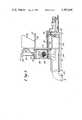
- FIG. 1is a sectional side view of a loading apparatus arranged over an injection molding machine injection unit.
- FIG. 2is a view taken along the lines II--II of FIG. 1;
- FIGS. 3, 4 and 5are sequential elevational views of an alternative embodiment of an injection unit loading apparatus for an injection molding machine.
- the stuffer loader 10in communication with a molding machine injection unit 12.
- the stuffer loader 10comprises a baseplate 14 on which a turntable 16 may rotate about an axis 18.
- the axis 18also comprises a tie rod 20 which together with several other tie rods 20 may form a triangular support arrangement for a platform 22.
- a plurality of cannisters or containers 24, two in this embodiment,are secured to the turntable 16.
- Each container 24is of cylindrical configuration, and is open at each end thereof.
- the opening in lower end of each container 24is fixedly aligned with an opening 26 in the turntable 16.
- the baseplate 14has an opening 28 aligned with the bottom of the container 24 in its discharge position as seen in FIG. 1.
- the platform 22is arranged parallel with the baseplate 14 and may support a divert hopper 30 and a double acting plunge cylinder 32, the divert hopper 30 and the plunge cylinder 32 preferably being 180° apart from one another about the tie rod 20, which comprises the axis 18 thereof, as shown in FIG. 2.
- the plunge cylinder 32comprises a piston 33, attached to a connecting rod 34 which is secured to main plunger 36 at its lower end thereof.
- An annular sealing sleeve 38is disposed beneath the platform 22 and is held thereadjacent by a plurality of threaded shafts 40 which each reciprocably slide through a channel 42 in the platform 22 and are each adapted to a drive cylinder 46 mounted on the top side of the platform 22.
- the drive cylinders 46are empowered by proper pressurizable means, not shown, to reciprocably move each of the threaded shafts 40.
- the plunge cylinder 32is empowered to reciprocably move the main plunger 36, by connection with a pressure source 48, shown only partially.
- the annular sealing sleeve 38has a stepped shoulder 50 on its distal edge, the shoulder 50 being arranged so as to overlap the upper edge of each container 24 when the drive cylinders 46 are pressurized to extend their shafts 40.
- An upper limit switch assembly 52is arranged adjacent to the plunge cylinder 32 at the top thereof and has a pin mechanism 54 which extends inside the plunge cylinder 32. The pin mechanism 54 is triggered when the piston 33, inside the plunge cylinder 32 is retracted to its upwardmost position.
- a lower limit switch assembly 56also has the pin mechanism 54 which extends inside the plunge cylinder 32, and which is triggered by contact when the piston 33 thereinside, is driven to its downwardmost position.
- the limit switch assemblies 52 and 56are connected with proper circuitry, not shown, to pressurization means, not shown, for the plunge cylinder 32 to sequentially actuate these devices accordingly.
- the turntable 16may be rotated by a stepping motor 60 arranged beneath the baseplate 14 and may be engaged with a pinion gear 62 or friction wheel that extends through the baseplate 14, and into engagement with a curvilinear surface 64 or arcuate gear disposed at least in part of a circular channel 66 in the bottom of the turntable.
- a desired quantity of materialmay be dropped into the divert hopper 30.
- the stepping motor 60is actuated by signal means to turn the turntable 16, with the containers 24, thereon, about 180° around their axis 18, so that the cylinder 24 which should have a quantity of material therein, is now disposed over the opening 28 in the baseplate 14.
- a cooled transition cone 68is disposed on the bottom side of the opening 28 against the baseplate 14, forming a conduit between the opening 26 and an inlet of the injection unit 12 of the injection molding machine.
- a proper signalmay cause the drive cylinders 46 to propel their respective shafts 40 downwardly, causing the distal edge of the annular sealing sleeve 38 to be pressed against the upper lip of the container 24 in an overlapping and sealing fashion.
- a signal from a proper circuitmay pressurize the plunge cylinder 32 to press the material dropped therein, into the transition cone 68, and into the inlet of the injection unit 12 of the injection molding machine.
- FIGS. 3, 4 and 5An alternative embodiment of this stuffer loader is shown sequentially in FIGS. 3, 4 and 5, wherein a quantity of material M is loaded into a refill hopper 80 of a reciprocal stuffer loader 82.
- the refill hopper 80is secured to a generally vertical disposed frame 84 arranged over a plunge cannister 88.
- a shut-off slide 88may be movably held under the refill hopper 80 to automatically slide back and forth to permit a particular quantity of material to fall into the cannister 86.
- the plunge cannister 86is disposed on a shuttle track 90.
- the shuttle track 90is movably disposed on a bedplate 92, and the shuttle track 90 is attached to pressurizable shuttle cylinder 94, and extends linearly to a position beneath a double-acting plunge cylinder 96 which has a recessed plunger 98 arranged similar to the aforementioned embodiment.
- the plunge cannister 86has an open bottom, and the bedplate 92 has an opening therethrough, beneath the plunger 98.
- a main stuffer unit 100is disposed beneath the bedplate 92 and has a reciprocable piston and cylinder arrangement 102, empowerable to push a main plunger, not shown, through a body 104 to effect movement of material therein, through a subsequent elbow 106, into an injection unit, not shown, but which may be similar to the injection unit shown in FIG. 1.
- a quantity of materialmay be dropped into the refill hopper 80 and then be dropped into the plunge cannister 86, as shown by arrows in FIG. 3.
- the shut-off slide 88may shut off the falling of material after a predetermined volume of material had passed thereby, by actuation of a pressurizable cylinder 110, through a proper circuit means, not shown.
- the cannister 86as shown in FIG.
- the plunger 98shown in FIG. 5, is actuated to force the material M through the open lower end of the cannister 86, and through the opening in the bedplate 92, into the body 104 of the stuffer unit 100 by signals generated through an arrangement of limit switches 101 and pin mechanisms 103 simlar to those in the aforementioned embodiment.
- the piston and cylinder arrangement 102are actuated by the necessary circuitry, to force the material from the body 104, through the elbow 106, and into either the feed throat or injection barrel of an injection unit of an injection molding machine.
- a further arrangement of the plunge cylindersmay comprise a pair of pressurizable cylinders which are connected to and spaced apart on a horizontal brace which supports a shaft therebetween, said shaft connected to a plunge piston, instead of having the pressurizable cylinder on top of the plunge piston, thereby eliminating a portion of the height of the plunge mechanism.
Landscapes
- Engineering & Computer Science (AREA)
- Mechanical Engineering (AREA)
- Robotics (AREA)
- Manufacturing & Machinery (AREA)
- Injection Moulding Of Plastics Or The Like (AREA)
- Processing And Handling Of Plastics And Other Materials For Molding In General (AREA)
Abstract
Description
Claims (2)
Priority Applications (4)
| Application Number | Priority Date | Filing Date | Title |
|---|---|---|---|
| US06/255,862US4397630A (en) | 1981-04-20 | 1981-04-20 | Apparatus for loading and injection unit of an injection molding machine |
| FR8206669AFR2504054A1 (en) | 1981-04-20 | 1982-04-19 | MECHANISM FOR LOADING, BY DISCHARGE, A MATERIAL IN A DEVICE FOR INJECTING AN INJECTION MOLDING MACHINE |
| JP57066205AJPS57193308A (en) | 1981-04-20 | 1982-04-20 | Charger to injecting unit of injection molding device |
| DE19823214597DE3214597A1 (en) | 1981-04-20 | 1982-04-20 | MATERIAL FEEDING MECHANISM |
Applications Claiming Priority (1)
| Application Number | Priority Date | Filing Date | Title |
|---|---|---|---|
| US06/255,862US4397630A (en) | 1981-04-20 | 1981-04-20 | Apparatus for loading and injection unit of an injection molding machine |
Publications (1)
| Publication Number | Publication Date |
|---|---|
| US4397630Atrue US4397630A (en) | 1983-08-09 |
Family
ID=22970170
Family Applications (1)
| Application Number | Title | Priority Date | Filing Date |
|---|---|---|---|
| US06/255,862Expired - Fee RelatedUS4397630A (en) | 1981-04-20 | 1981-04-20 | Apparatus for loading and injection unit of an injection molding machine |
Country Status (4)
| Country | Link |
|---|---|
| US (1) | US4397630A (en) |
| JP (1) | JPS57193308A (en) |
| DE (1) | DE3214597A1 (en) |
| FR (1) | FR2504054A1 (en) |
Cited By (6)
| Publication number | Priority date | Publication date | Assignee | Title |
|---|---|---|---|---|
| US4629410A (en)* | 1982-07-28 | 1986-12-16 | Karl Hehl | Dual-hopper injection unit for injection molding machine |
| DE3633835A1 (en)* | 1986-10-04 | 1988-04-14 | Ernst Sauerbruch | FEEDING DEVICE FOR INJECTION MOLDING MACHINES |
| US4826425A (en)* | 1985-09-12 | 1989-05-02 | Ngk Insulators, Ltd. | Constant amount ceramic batch supplying apparatus |
| DE10025597A1 (en)* | 2000-05-24 | 2001-12-06 | Krauss Maffei Kunststofftech | Device and method for loading the plasticizing unit of an injection molding machine |
| WO2002092310A1 (en)* | 2001-05-17 | 2002-11-21 | Tesa Ag | Transport of highly viscous fluids in closed pipeline systems |
| US20180290345A1 (en)* | 2015-05-14 | 2018-10-11 | Wittmann Canada Inc. | Method And System Of Vacuum Loading |
Families Citing this family (4)
| Publication number | Priority date | Publication date | Assignee | Title |
|---|---|---|---|---|
| DE3336036A1 (en)* | 1983-10-04 | 1985-04-18 | Krauss-Maffei AG, 8000 München | PISTON DOSING DEVICE OF A REACTION CASTING MACHINE |
| DE3633924A1 (en)* | 1986-10-04 | 1988-04-07 | Ernst Sauerbruch | METHOD FOR LOADING AN INJECTION MOLDING MACHINE AND DEVICE FOR CARRYING OUT THE METHOD |
| AT396444B (en)* | 1990-10-02 | 1993-09-27 | Silhouette Int Gmbh | METHOD AND DEVICE FOR CHANGING COLORS IN INJECTION MOLDING PLASTICS |
| EP0483574A3 (en)* | 1990-11-01 | 1992-11-19 | Bucher-Guyer Ag Maschinenfabrik | Feeding device for a plastification unit |
Citations (4)
| Publication number | Priority date | Publication date | Assignee | Title |
|---|---|---|---|---|
| US1890802A (en)* | 1929-09-21 | 1932-12-13 | Vincent G Apple | Automatic molding method and machine |
| US2243968A (en)* | 1938-04-15 | 1941-06-03 | Lester Engineering Co | Plastic casting machine |
| US2658237A (en)* | 1948-12-14 | 1953-11-10 | Hydraulic Molds Corp | Injection molding apparatus |
| US3492699A (en)* | 1967-07-31 | 1970-02-03 | Borg Warner | Blow molding plasticizing apparatus |
Family Cites Families (6)
| Publication number | Priority date | Publication date | Assignee | Title |
|---|---|---|---|---|
| DE918230C (en)* | 1952-08-28 | 1954-09-23 | Siemens Ag | Device for feeding powdery masses, in particular thermoplastic plastics masses, in processing machines |
| US2841824A (en)* | 1953-11-09 | 1958-07-08 | Wilfred G Harvey | Feed mechanism for injection molding machine |
| GB826470A (en)* | 1956-12-06 | 1960-01-06 | Wilhelm Ellinghaus | Device for measuring, moulding and delivering plastic materials |
| FR2087546A5 (en)* | 1970-05-22 | 1971-12-31 | Porchon Maurice | Feed device - for feeding adhesive paste material eg silicone to extruder |
| DE2702649A1 (en)* | 1977-01-22 | 1978-07-27 | Elbatainer Kunststoff | Polyethylene extruder feeding device - has hopper discharge opening provided with reciprocable presser foot whose stroke is controlled by end switches |
| GB2076730B (en)* | 1980-06-02 | 1984-06-06 | Pont A Mousson | Device for the injection of plastics materials elastomers or other similar materials |
- 1981
- 1981-04-20USUS06/255,862patent/US4397630A/ennot_activeExpired - Fee Related
- 1982
- 1982-04-19FRFR8206669Apatent/FR2504054A1/ennot_activeWithdrawn
- 1982-04-20DEDE19823214597patent/DE3214597A1/ennot_activeWithdrawn
- 1982-04-20JPJP57066205Apatent/JPS57193308A/enactivePending
Patent Citations (4)
| Publication number | Priority date | Publication date | Assignee | Title |
|---|---|---|---|---|
| US1890802A (en)* | 1929-09-21 | 1932-12-13 | Vincent G Apple | Automatic molding method and machine |
| US2243968A (en)* | 1938-04-15 | 1941-06-03 | Lester Engineering Co | Plastic casting machine |
| US2658237A (en)* | 1948-12-14 | 1953-11-10 | Hydraulic Molds Corp | Injection molding apparatus |
| US3492699A (en)* | 1967-07-31 | 1970-02-03 | Borg Warner | Blow molding plasticizing apparatus |
Cited By (11)
| Publication number | Priority date | Publication date | Assignee | Title |
|---|---|---|---|---|
| US4629410A (en)* | 1982-07-28 | 1986-12-16 | Karl Hehl | Dual-hopper injection unit for injection molding machine |
| US4826425A (en)* | 1985-09-12 | 1989-05-02 | Ngk Insulators, Ltd. | Constant amount ceramic batch supplying apparatus |
| DE3633835A1 (en)* | 1986-10-04 | 1988-04-14 | Ernst Sauerbruch | FEEDING DEVICE FOR INJECTION MOLDING MACHINES |
| DE10025597A1 (en)* | 2000-05-24 | 2001-12-06 | Krauss Maffei Kunststofftech | Device and method for loading the plasticizing unit of an injection molding machine |
| DE10025597C2 (en)* | 2000-05-24 | 2002-07-11 | Krauss Maffei Kunststofftech | Device and method for loading the plasticizing unit of an injection molding machine |
| US6623153B2 (en)* | 2000-05-24 | 2003-09-23 | Krauss-Maffei Kunststofftechnik Gmbh | Device and method for charging a plasticizing unit of an injection molding machine |
| WO2002092310A1 (en)* | 2001-05-17 | 2002-11-21 | Tesa Ag | Transport of highly viscous fluids in closed pipeline systems |
| US20040232161A1 (en)* | 2001-05-17 | 2004-11-25 | Sven Konig | Transport of highly viscous fluids in closed pipeline systems |
| US7252111B2 (en)* | 2001-05-17 | 2007-08-07 | Tesa Aktiengesellschaft | Transport of highly viscous fluids in closed pipeline systems |
| US20180290345A1 (en)* | 2015-05-14 | 2018-10-11 | Wittmann Canada Inc. | Method And System Of Vacuum Loading |
| US10507605B2 (en)* | 2015-05-14 | 2019-12-17 | Wittmann Battenfeld Canada Inc. | Method and system of vacuum loading |
Also Published As
| Publication number | Publication date |
|---|---|
| DE3214597A1 (en) | 1982-11-04 |
| JPS57193308A (en) | 1982-11-27 |
| FR2504054A1 (en) | 1982-10-22 |
Similar Documents
| Publication | Publication Date | Title |
|---|---|---|
| US4397630A (en) | Apparatus for loading and injection unit of an injection molding machine | |
| US4542835A (en) | Method for filling containers with metered quantities of powdered materials | |
| US3124916A (en) | Filling and capping machine | |
| CN209972826U (en) | Filling equipment | |
| US4422842A (en) | Apparatus for injecting plastics and elastomers | |
| US4163354A (en) | Method and apparatus for filling capsules | |
| CN112454797B (en) | Injection molding system and injection molding method | |
| US3005231A (en) | Machine for producing hollow bodies of thermoplastic synthetics by extruding and blowing | |
| US4051878A (en) | Rotary filler apparatus | |
| US5030080A (en) | Resin material supply apparatus to resin press molding machine | |
| US4397806A (en) | Method and apparatus for mold injection | |
| US3213587A (en) | Method for packing compressible materials into containers | |
| US3357155A (en) | Machine for packing compressible materials into containers | |
| US2975809A (en) | Loading and unloading apparatus | |
| US3877862A (en) | Feeder for multi-cavity compression molding apparatus | |
| KR102850503B1 (en) | Machine and method for filling capsules | |
| US2602578A (en) | Apparatus for packing materials | |
| US3939899A (en) | Shell molding machine in which blown core can be ejected outside vise assembly | |
| CA1072288A (en) | Molding machine for producing casting molds | |
| US2451301A (en) | Apparatus for the molding of butter and like products | |
| US2927499A (en) | Powder consolidating press | |
| US3427960A (en) | Compacting machine | |
| US4003498A (en) | Method and apparatus for controlled feeding of friction material | |
| US3994333A (en) | Core blowing machine | |
| US4450888A (en) | Moulding plant |
Legal Events
| Date | Code | Title | Description |
|---|---|---|---|
| AS | Assignment | Owner name:USM CORPORATION OF FLEMINGTON, NEW JERSEY, 426 COL Free format text:ASSIGNMENT OF ASSIGNORS INTEREST.;ASSIGNOR:MEEKER, GREGORY W;REEL/FRAME:004019/0684 Effective date:19810408 Owner name:USM CORPORATION OF FLEMINGTON, NEW JERSEY, 426 COL Free format text:ASSIGNMENT OF ASSIGNORS INTEREST;ASSIGNOR:MEEKER, GREGORY W;REEL/FRAME:004019/0684 Effective date:19810408 | |
| AS | Assignment | Owner name:FARREL CORPORATION, 25 MAIN STREET, ANSONIA, CONNE Free format text:ASSIGNMENT OF ASSIGNORS INTEREST.;ASSIGNOR:USM CORPORATION A CORP. OF NJ;REEL/FRAME:004570/0176 Effective date:19860512 | |
| AS | Assignment | Owner name:FOOTHILL CAPITAL CORPORATION, A CORP. OF CA, CALIF Free format text:SECURITY INTEREST;ASSIGNOR:FARREL CORPORATION;REEL/FRAME:004588/0706 Effective date:19860506 | |
| FEPP | Fee payment procedure | Free format text:MAINTENANCE FEE REMINDER MAILED (ORIGINAL EVENT CODE: REM.); ENTITY STATUS OF PATENT OWNER: LARGE ENTITY | |
| LAPS | Lapse for failure to pay maintenance fees | ||
| STCH | Information on status: patent discontinuation | Free format text:PATENT EXPIRED DUE TO NONPAYMENT OF MAINTENANCE FEES UNDER 37 CFR 1.362 | |
| FP | Lapsed due to failure to pay maintenance fee | Effective date:19870809 | |
| AS | Assignment | Owner name:FARREL CORPORATION, 25 MAIN ST., ANSONIA, CT 06401 Free format text:RELEASED BY SECURED PARTY;ASSIGNOR:FOOTHILL CAPITAL CORPORATION;REEL/FRAME:004998/0926 Effective date:19881004 Owner name:FARREL CORPORATION, CONNECTICUT Free format text:RELEASED BY SECURED PARTY;ASSIGNOR:FOOTHILL CAPITAL CORPORATION;REEL/FRAME:004998/0926 Effective date:19881004 |