US4397303A - Heat exchanger for concentrating solar collectors and method for making the heat exchanger - Google Patents
Heat exchanger for concentrating solar collectors and method for making the heat exchangerDownload PDFInfo
- Publication number
- US4397303A US4397303AUS06/232,573US23257381AUS4397303AUS 4397303 AUS4397303 AUS 4397303AUS 23257381 AUS23257381 AUS 23257381AUS 4397303 AUS4397303 AUS 4397303A
- Authority
- US
- United States
- Prior art keywords
- plates
- heat exchanger
- solar energy
- assembly according
- collecting assembly
- Prior art date
- Legal status (The legal status is an assumption and is not a legal conclusion. Google has not performed a legal analysis and makes no representation as to the accuracy of the status listed.)
- Expired - Fee Related
Links
- 238000000034methodMethods0.000titleclaimsdescription13
- 239000012530fluidSubstances0.000claimsabstractdescription49
- 230000005855radiationEffects0.000claimsabstractdescription31
- 239000004020conductorSubstances0.000claimsabstractdescription4
- 239000011248coating agentSubstances0.000claimsdescription7
- 238000000576coating methodMethods0.000claimsdescription7
- 230000013011matingEffects0.000claims2
- 239000007788liquidSubstances0.000claims1
- 238000004519manufacturing processMethods0.000abstractdescription3
- 239000007787solidSubstances0.000description4
- 238000006243chemical reactionMethods0.000description3
- 238000003754machiningMethods0.000description3
- XLYOFNOQVPJJNP-UHFFFAOYSA-NwaterSubstancesOXLYOFNOQVPJJNP-UHFFFAOYSA-N0.000description3
- 238000001816coolingMethods0.000description2
- 210000005069earsAnatomy0.000description2
- 239000000463materialSubstances0.000description2
- 239000006096absorbing agentSubstances0.000description1
- XAGFODPZIPBFFR-UHFFFAOYSA-NaluminiumChemical compound[Al]XAGFODPZIPBFFR-UHFFFAOYSA-N0.000description1
- 229910052782aluminiumInorganic materials0.000description1
- 230000000903blocking effectEffects0.000description1
- 238000010276constructionMethods0.000description1
- 238000005553drillingMethods0.000description1
- 238000010438heat treatmentMethods0.000description1
- 238000009434installationMethods0.000description1
- 238000012986modificationMethods0.000description1
- 230000004048modificationEffects0.000description1
- 238000004080punchingMethods0.000description1
- 230000000284resting effectEffects0.000description1
- 239000002918waste heatSubstances0.000description1
- 238000003466weldingMethods0.000description1
Images


Classifications
- H—ELECTRICITY
- H10—SEMICONDUCTOR DEVICES; ELECTRIC SOLID-STATE DEVICES NOT OTHERWISE PROVIDED FOR
- H10F—INORGANIC SEMICONDUCTOR DEVICES SENSITIVE TO INFRARED RADIATION, LIGHT, ELECTROMAGNETIC RADIATION OF SHORTER WAVELENGTH OR CORPUSCULAR RADIATION
- H10F77/00—Constructional details of devices covered by this subclass
- H10F77/40—Optical elements or arrangements
- H10F77/42—Optical elements or arrangements directly associated or integrated with photovoltaic cells, e.g. light-reflecting means or light-concentrating means
- H10F77/488—Reflecting light-concentrating means, e.g. parabolic mirrors or concentrators using total internal reflection
- F—MECHANICAL ENGINEERING; LIGHTING; HEATING; WEAPONS; BLASTING
- F24—HEATING; RANGES; VENTILATING
- F24S—SOLAR HEAT COLLECTORS; SOLAR HEAT SYSTEMS
- F24S10/00—Solar heat collectors using working fluids
- F24S10/50—Solar heat collectors using working fluids the working fluids being conveyed between plates
- F24S10/502—Solar heat collectors using working fluids the working fluids being conveyed between plates having conduits formed by paired plates and internal partition means
- F—MECHANICAL ENGINEERING; LIGHTING; HEATING; WEAPONS; BLASTING
- F24—HEATING; RANGES; VENTILATING
- F24S—SOLAR HEAT COLLECTORS; SOLAR HEAT SYSTEMS
- F24S20/00—Solar heat collectors specially adapted for particular uses or environments
- F24S20/20—Solar heat collectors for receiving concentrated solar energy, e.g. receivers for solar power plants
- F—MECHANICAL ENGINEERING; LIGHTING; HEATING; WEAPONS; BLASTING
- F24—HEATING; RANGES; VENTILATING
- F24S—SOLAR HEAT COLLECTORS; SOLAR HEAT SYSTEMS
- F24S23/00—Arrangements for concentrating solar-rays for solar heat collectors
- F24S23/30—Arrangements for concentrating solar-rays for solar heat collectors with lenses
- H—ELECTRICITY
- H02—GENERATION; CONVERSION OR DISTRIBUTION OF ELECTRIC POWER
- H02S—GENERATION OF ELECTRIC POWER BY CONVERSION OF INFRARED RADIATION, VISIBLE LIGHT OR ULTRAVIOLET LIGHT, e.g. USING PHOTOVOLTAIC [PV] MODULES
- H02S40/00—Components or accessories in combination with PV modules, not provided for in groups H02S10/00 - H02S30/00
- H02S40/40—Thermal components
- H02S40/44—Means to utilise heat energy, e.g. hybrid systems producing warm water and electricity at the same time
- H—ELECTRICITY
- H10—SEMICONDUCTOR DEVICES; ELECTRIC SOLID-STATE DEVICES NOT OTHERWISE PROVIDED FOR
- H10F—INORGANIC SEMICONDUCTOR DEVICES SENSITIVE TO INFRARED RADIATION, LIGHT, ELECTROMAGNETIC RADIATION OF SHORTER WAVELENGTH OR CORPUSCULAR RADIATION
- H10F77/00—Constructional details of devices covered by this subclass
- H10F77/60—Arrangements for cooling, heating, ventilating or compensating for temperature fluctuations
- H10F77/63—Arrangements for cooling directly associated or integrated with photovoltaic cells, e.g. heat sinks directly associated with the photovoltaic cells or integrated Peltier elements for active cooling
- H10F77/68—Arrangements for cooling directly associated or integrated with photovoltaic cells, e.g. heat sinks directly associated with the photovoltaic cells or integrated Peltier elements for active cooling using gaseous or liquid coolants, e.g. air flow ventilation or water circulation
- Y—GENERAL TAGGING OF NEW TECHNOLOGICAL DEVELOPMENTS; GENERAL TAGGING OF CROSS-SECTIONAL TECHNOLOGIES SPANNING OVER SEVERAL SECTIONS OF THE IPC; TECHNICAL SUBJECTS COVERED BY FORMER USPC CROSS-REFERENCE ART COLLECTIONS [XRACs] AND DIGESTS
- Y02—TECHNOLOGIES OR APPLICATIONS FOR MITIGATION OR ADAPTATION AGAINST CLIMATE CHANGE
- Y02E—REDUCTION OF GREENHOUSE GAS [GHG] EMISSIONS, RELATED TO ENERGY GENERATION, TRANSMISSION OR DISTRIBUTION
- Y02E10/00—Energy generation through renewable energy sources
- Y02E10/40—Solar thermal energy, e.g. solar towers
- Y02E10/44—Heat exchange systems
- Y—GENERAL TAGGING OF NEW TECHNOLOGICAL DEVELOPMENTS; GENERAL TAGGING OF CROSS-SECTIONAL TECHNOLOGIES SPANNING OVER SEVERAL SECTIONS OF THE IPC; TECHNICAL SUBJECTS COVERED BY FORMER USPC CROSS-REFERENCE ART COLLECTIONS [XRACs] AND DIGESTS
- Y02—TECHNOLOGIES OR APPLICATIONS FOR MITIGATION OR ADAPTATION AGAINST CLIMATE CHANGE
- Y02E—REDUCTION OF GREENHOUSE GAS [GHG] EMISSIONS, RELATED TO ENERGY GENERATION, TRANSMISSION OR DISTRIBUTION
- Y02E10/00—Energy generation through renewable energy sources
- Y02E10/50—Photovoltaic [PV] energy
- Y02E10/52—PV systems with concentrators
- Y—GENERAL TAGGING OF NEW TECHNOLOGICAL DEVELOPMENTS; GENERAL TAGGING OF CROSS-SECTIONAL TECHNOLOGIES SPANNING OVER SEVERAL SECTIONS OF THE IPC; TECHNICAL SUBJECTS COVERED BY FORMER USPC CROSS-REFERENCE ART COLLECTIONS [XRACs] AND DIGESTS
- Y02—TECHNOLOGIES OR APPLICATIONS FOR MITIGATION OR ADAPTATION AGAINST CLIMATE CHANGE
- Y02E—REDUCTION OF GREENHOUSE GAS [GHG] EMISSIONS, RELATED TO ENERGY GENERATION, TRANSMISSION OR DISTRIBUTION
- Y02E10/00—Energy generation through renewable energy sources
- Y02E10/60—Thermal-PV hybrids
- Y—GENERAL TAGGING OF NEW TECHNOLOGICAL DEVELOPMENTS; GENERAL TAGGING OF CROSS-SECTIONAL TECHNOLOGIES SPANNING OVER SEVERAL SECTIONS OF THE IPC; TECHNICAL SUBJECTS COVERED BY FORMER USPC CROSS-REFERENCE ART COLLECTIONS [XRACs] AND DIGESTS
- Y10—TECHNICAL SUBJECTS COVERED BY FORMER USPC
- Y10S—TECHNICAL SUBJECTS COVERED BY FORMER USPC CROSS-REFERENCE ART COLLECTIONS [XRACs] AND DIGESTS
- Y10S126/00—Stoves and furnaces
- Y10S126/907—Absorber coating
- Y—GENERAL TAGGING OF NEW TECHNOLOGICAL DEVELOPMENTS; GENERAL TAGGING OF CROSS-SECTIONAL TECHNOLOGIES SPANNING OVER SEVERAL SECTIONS OF THE IPC; TECHNICAL SUBJECTS COVERED BY FORMER USPC CROSS-REFERENCE ART COLLECTIONS [XRACs] AND DIGESTS
- Y10—TECHNICAL SUBJECTS COVERED BY FORMER USPC
- Y10T—TECHNICAL SUBJECTS COVERED BY FORMER US CLASSIFICATION
- Y10T29/00—Metal working
- Y10T29/49—Method of mechanical manufacture
- Y10T29/4935—Heat exchanger or boiler making
- Y10T29/49355—Solar energy device making
- Y—GENERAL TAGGING OF NEW TECHNOLOGICAL DEVELOPMENTS; GENERAL TAGGING OF CROSS-SECTIONAL TECHNOLOGIES SPANNING OVER SEVERAL SECTIONS OF THE IPC; TECHNICAL SUBJECTS COVERED BY FORMER USPC CROSS-REFERENCE ART COLLECTIONS [XRACs] AND DIGESTS
- Y10—TECHNICAL SUBJECTS COVERED BY FORMER USPC
- Y10T—TECHNICAL SUBJECTS COVERED BY FORMER US CLASSIFICATION
- Y10T29/00—Metal working
- Y10T29/49—Method of mechanical manufacture
- Y10T29/49826—Assembling or joining
Definitions
- the present inventionrelates generally to concentrating solar collectors for converting solar radiation to electrical or heat energy, and more particularly to a single fluid heat exchanger for cooling such photovoltaic cells.
- a pair of spaced upwardly and outwardly extending side wallsform an elongated trough-like collector housing of generally truncated conical-shaped cross section.
- Solar radiation conversion meanssuch as a photovoltaic cell or solar radiation to heat conversion means may be positioned at the narrow end or focal point of the concentrator so that the incident solar radiation is concentrated within a relatively small area.
- photovoltaic cellsIn the type of solar collector described using photovoltaic cells, it is well-known that a plurality of such photovoltaic cells may be placed at spaced locations along the longitudinal axis of the collector housing and connected electrically to increase the voltage or current output from the collector. In addition, the entire assembly may be pivotally mounted to track the sun and thereby maximize the amount of solar radiation incident on the photovoltaic cells.
- a common problem associated with such collectorsis the fact that the energy conversion of the photovoltaic cells is relatively inefficient, resulting in production of significant quantities of waste heat which must be quickly and efficiently dissipated to prevent damage to the cells. Consequently, the cells are often mounted upon a heat conducting plate or similar support forming part of a heat exchanger for conducting heat away from the cell.
- a typical heat exchange assemblyincludes an enlongated conduit extending parallel to the narrow end of the collector housing beneath the cells for carrying a flowing heat exchange fluid such as air, water or the like.
- a solid metallic plug-like member having a plurality of spaced parallel drilled-through holes oriented in the direction of fluid flowis inserted through an opening in the top of the conduit, and the photovoltaic cell mounted in heat exchange relationship on the top of the member.
- a typical heat exchanger assemblyincludes an elongated conduit extending parallel to the narrow end of the collector housing having an upper heat conducting surface exposed to the incident solar radiation, with the conduit carrying a flowing heat exchange fluid such as air, water or the like.
- the heat exchanging elementmay comprise a solid metallic member having a plurality of spaced parallel drilled through holes oriented in the direction of fluid flow.
- the present inventionis directed to a heat exchanger design for use in the type of concentrating solar collectors described hereinabove which can be manufactured with a significant savings in cost over conventional heat exchangers, and can moreover be reliably and easily installed in the heat exchange fluid conduit.
- the heat exchanger of the present inventioncomprisies a plurality of stacked flat round or square disc-like heat exchanger plates, each of the plates bearing a plurality of spaced parallel grooves on one surface.
- the platesare oriented by keying means to prevent relative rotation between the plates, and to orient the grooves of adjacent plates in non-contiguous parallel relationship to form a plurality of spaced parallel flow passages extending in the direction of heat exchange fluid flow.
- Each of the heat exchanger platesmay be easily fabricated by stamping or the like and held in place within the heat exchanger conduit by means of upper and lower keying members.
- the upper memberis provided with a substantially planar upper surface for supporting the photovoltaic cell in heat conducting relationship so that heat removed from the cell may be easily transmitted through the upper member, and the stacked plates to the heat exchange fluid flowing through the flow passages.
- the upper surfacemay form an absorber for converting solar radiation to heat.
- the lower heat exchanger memberincludes an upper plate-like surface configured to abut the lower surface of the lowermost one of said plates and a web-like member resting upon the inner lower surface of the fluid conduit and conforming to the cross sectional shape of the conduit so as to block fluid flow through the lower part of the conduit.
- the side edges of the web-like portion of the lower membermay be provided with grooves cooperating with keying members secured to the sides of the conduit to secure the heat exchanger in place, and also to facilitate assembly of the heat exchanger so that the flow passages formed between the heat exchanger plates can be oriented only in the direction of heat exchange fluid flow.
- the heat exchanger platesmay be provided, by punching or the like, with a plurality of spaced openings or perforations.
- the coaxially oriented perforationsform channels extending parallel to the direction of flow of the heat exchanger fluid. Keying means may also be provided with this embodiment to facilitate accurate placement within the flow conduit.
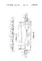
- FIG. 1is a top plan view of a first embodiment of the concentrating solar collector of the present invention illustrating several photovoltaic cell stations.
- FIG. 2is a fragmentary front cut-away plan view of the embodiment shown in FIG. 1 illustrating the end supports for the collector housing and a single photovoltaic cell station.
- FIG. 3is an enlarged fragmentary top plan view of the concentrating solar collector of FIG. 1 illustrating two photovoltaic cell stations.
- FIG. 4is an enlarged cross sectional end view taken along section line 4--4 of FIG. 3.
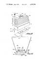
- FIG. 5is an exploded end view of the heat exchanger used in the embodiment of FIG. 1.
- FIG. 6is a side elevation view of the heat exchanger of FIG. 5.
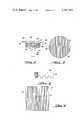
- FIG. 7is a bottom elevation view of a single round heat exchanger plate used in the heat exchanger of FIG. 5.
- FIG. 8is a fragmentary cross sectional view of the heat exchanger plate of FIG. 7.
- FIG. 9is a bottom elevation view of a single square heat exchanger plate usuable in the heat exchanger of FIG. 5.
- FIG. 10is a cross sectional end view of a second embodiment of the present invention.
- FIG. 11is a cross sectional end view of a third embodiment of the present invention.
- FIG. 12is an exploded perspective view of the heat exchanger plate arrangement of the embodiment of FIG. 11.
- FIG. 13is a cross sectional end view of a fourth embodiment of the present invention.
- FIG. 14is an exploded perspective view of the heat exchanger plate arrangement of the embodiment of FIG. 13.
- Collector 1comprises a pair of generally planar spaced upwardly and outwardly sloping side walls or panels 2 forming an elongated trough-like concentrating collector housing 3.
- the upper end of housing 3may be provided with a suitable concentrating lens (not shown).
- the ends of housing 3are closed by means of vertically extending plate-like trapezoidal-shaped bulkheads 4 supporting an outwardly extending horizontal tube-like shaft 5.
- Each of shafts 5is supported by a journal bearing 6 to permit the entire collector 1 to pivot about a substantially horizontal axis extending parallel to the longitudinal axis of the collector.
- the angular position of collector 1may be adjusted to track the sun and maximize the solar radiation impinging on the collecting means positioned within the collector housing as will be described in more detail hereinafter.
- each station 7includes a photovoltaic cell assembly 8 of conventional design positioned at approximately the focal point in the narrow end of collector housing 3.
- Cell assembly 8is supported and cooled by a heat exchanger assembly 9 which will be described in more detail hereinafter.
- collector housing 3is also provided with an elongated channel-shaped conduit 14 of generally rectangular cross section having spaced side walls 15, lower wall 16, and upper wall 17.
- An angle bracket 18extends outwardly from the side walls 15 and forms a point of attachment for side walls or panels 2 of collector housing 3 as at 19.
- the upper wall 17 of conduit 14is provided with a plurality of spaced generally circular openings 20 dimensioned to accept heat exchanger assembly 9.
- heat exchanger assembly 9comprises an upper segment 21, a plurality of heat exchanger plates 22, and lower segment 23.
- Upper segment 21comprises a generally circular plate 24 having a substantially planar smooth upper surface 25 for supporting the photovoltaic cell assembly 8 in heat conducting relationship as best shown in FIG. 4.
- Circular plate 24is also provided with a number of circumferentially spaced apertures 26 for cooperating with threaded studs 27 secured to the upper wall 17 of conduit 14 circumferentially around opening 20 to securely hold heat exchanger assembly 9 and photovoltaic cell assembly 8 in position.
- Cushioning means 28 in the form of a resilient gasket or the likemay also be provided between the lower outer edge of circular plate 24 and the upper surface of upper wall 17 adjacent opening 20.
- the lower surface of circular plate 24is provided with a downwardly depending keying member 29 of generally rectangular cross section.
- heat exchanger plates 22comprise a generally flat round disc bearing a plurality of spaced parallel grooves 30 on one surface.
- plates 22may be square in shape as illustrated in FIG. 9, or other shapes to conform to the internal configuration of conduit 14. It will be understood that the size and cross sectional configuration of grooves 30 may be varied as desired for particular applications.
- some or all of heat exchanger plates 22may be provided with similarly configured grooves 30 on both sides of the plates.
- a generally rectangular central opening 31is provided in plate 22 and is dimensioned to mate with keying member 29 in order to orient grooves 30 of adjacent plates in non-contiguous parallel relationship to form a plurality of spaced parallel flow passages, as well as to prevent relative rotation between the plates and upper segment 21.
- grooves 30 forming the flow passagesare oriented in a direction generally parallel to the longitudinal axis of conduit 14.
- Grooves 30may be provided on the appropriate surface or surfaces of heat exchanger plate 22 by machining or stamping, this latter method being preferred in order to facilitate fabrication of the plate inasmuch as a plurality of plates may be stamped from a single sheet of material and provided with the appropriate grooves at the same time.
- heat exchanger 9has been provided with six heat exchanger plates 22. However, it will be understood that any number of plates may be used in a particular application.
- each side wall 15 of conduit 14is provided with a vertically positioned plug member 35 extending inwardly for effectively blocking the space between the side edges of web-like member 33 and the inner surfaces of side wall 15.
- Each plug member 35is further provided with an inwardly extending vertically oriented tab member 36 which cooperates with matching grooves 37 in the outer edges of web-like member 33.
- grooves 37cooperate with tab members 36 to orient the flow passages formed by grooves 30 in heat exchanger plates 22 in a direction parallel to the longitudinal axis of conduit 14 and also prevent relative movement of the entire heat exchanger assembly 9 with respect to conduit 14.
- heat exchanger assembly 9may be fabricated from any suitable heat conducting material such as aluminum or the like.
- conduit 14has been described and illustrated as having a generally rectangular cross section, it will be understood that various other shapes such as cylindrical, semi-cylindrical and the like may be utilized with a corresponding modification made to the shape of heat exchanger assembly 9.
- each heat exchanger assembly 9may be inserted as an entire unit or individual components through opening 20 in conduit 14 such that apertures 26 in circular plate 24 are positioned over threaded studs 27.
- heat exchanger assembly 9may be inserted into conduit 14 in only one way in order to permit grooves 37 in web-like member 33 to mate with inwardly extending tab members 36. Consequently, all grooves 30 are oriented in a direction parallel to the longitudinal axis of conduit 14, and cannot become misaligned.
- the photovoltaic cell assembly 8may be positioned on the upper surface 25 of circular plate 24, and held in place by means of nuts, one of which is shown at 38, cooperating with threaded studs 27.
- the electrical connections to connecting ears 10may then be made as illustrated.
- a suitable heat exchange fluidsuch as air, water or the like may be directed through conduit 14 by means not shown.
- the fluidis forced to flow through the flow passages formed by grooves 30 in the heat exchanger plates 22.
- Heat produced by the photovoltaic cell assembly 8may then be conducted through circular plate 24 and heat exchanger plates 22 to the heat conducting fluid.
- FIG. 10A second embodiment of a concentrating solar collector using the heat exchanger of the present invention in connection with means for converting incident solar radiation to heat is illustrated in FIG. 10, where elements similar to those previously described have been similarly designated.
- heat exchanger assembly 9is constructed in a manner identical with that previously described, except that the upper surface 25 of circular plate 24 is provided with a solar radiation absorbing coating 25a which serves to convert incident solar radiation falling on surface 25 to usable heat.
- the means previously desribed to mount the photovoltaic cells, and the cells themselves,have been eliminated in this embodiment.
- a concentrating lens 100may be provided so as to be supported by the upper longitudinal edges of side walls or panels 2 which form the elongated trough-like concentrating collector housing 3. It will be understood that lens 100 is so constructed as to focus solar radiation on the coated surface 25a of the heat exchanger assembly 9.
- FIG. 11 and FIG. 12Another embodiment of the heat exchanger assembly, designated 90, is illustrated in FIG. 11 and FIG. 12.
- the upper wall 17 of channel-shaped conduit 14has been eliminated along the length of the conduit.
- the supporting flanges, designated 14a in FIG. 11,have been turned outwardly, rather than extending inwardly as in the embodiments previously described.
- the details of the collector housing 3 and lens 100may also be as previously described.
- the heat exchanger assemblyshown generally at 90, comprises an elongated block-like solid member 91 positioned in the lower trough-like portion of conduit 14, which extends the length of the conduit and serves to block fluid flow through that portion of the conduit.
- a plurality of thin elongated heat exchanger plates 92 of generally rectangular shapeare arranged in stacked relationship on top of member 91.
- each of plates 92is provided with a plurality of parallel extending grooves or notches, one of which is shown at 93, which will be oriented in the direction of fluid flow within conduit 14 when the plates are positioned as illustrated in FIG. 11.
- grooves 93are shown extending along the lower surfaces of plates 92; however, it will be understood that the grooves may also be provided on the upper surface of the plates, or on both surfaces as previously described.
- a solid rectangular-shaped heat conducting plate 96which may include a solar radiation absorbing coating 97 on its upper surface, is positioned in heat conducting relationship with the uppermost one of plates 92 so as to extend between and be supported by flanges 14a.
- Plate 96holds plates 92 in position by means of apertures 94 which cooperate with threaded studs 95, and may be secured to channel 14 by means of lock nuts or the like 98. It will be observed that this arrangement permits a heat exchanging assembly which extends substantially the entire length of the solar collector.
- plates 92 and 96may be provided in separate sections placed end-to-end, or may be formed from plates which extend the entire length of the collector.
- member 91may be reduced in thickness or eliminated altogether, so that the entire interior of channel 14 is filled with longitudinally extending stacked plates 92.
- FIGS. 13 and 14Another embodiment of the present invention is illustrated in FIGS. 13 and 14, where elements similar to those previously described have been similarly designated.
- a channel-like conduit 140is utilized having inwardly extending flange portions 140a and an upper opening 141 extending substantially the length of the conduit and collector.
- the solar collector constructionis similar to that described hereinbefore in connection with the embodiment of FIG. 11 and FIG. 12, except that the heat exchanger assembly, designated in this embodiment at 190, is formed from a plurality of vertically extending plates 192 having a plurality of spaced openings or bores 193 extending therethrough.
- a lower block-like elongated member 91is positioned in the lower part of conduit 140 so as to block fluid flow in the lower portion of the conduit.
- a vertically extending block-like member 194is provided along the sides of conduit 140 adjacent the side walls to block fluid flow in this area.
- plates 192are positioned on edge on the upper surface of member 91 so as to extend between side members 194 substantially perpendicular to the direction of fluid flow. Plates 192 are also positioned one behind the other so that the openings 193 are substantially coaxial, forming channels through which the fluid may flow and absorb heat from the heated plates 192. If desired, openings 193 may be offset in adjacent plates so as to form a circuitous flow path. In addition, the plates 192 may be positioned abutting each other, or may be spaced along the length of conduit 140. To hold plates 192 in position, a plurality of spaced vertically extending grooves 195 may be provided along the interior edge of side members 194. Alternatively, or in addition to grooves 195, a plurality of horizontally extending spaced parallel grooves 196 may be provided in the lower surface of upper plate 96 so as to hold the upper edges of plate 192.
- a "stack" of the heat exchanger plates or “stacking" the heat exchanger platesrefers to arranging the plates in either touching adjacent relationship as shown, for example, in the embodiment of FIG. 4-FIG. 6 or FIG. 10-FIG. 12, or in non-touching adjacent relationship as illustrated, for example, in the embodiments of FIG. 13-FIG. 14.
- means for converting solar radiation to heat energyincludes photovoltaic cells such as included in photovoltaic cell assembly 8 as well as flat plate collectors of the type exemplified by plate 24 provided with solar radiation absorbing coating 25a.
Landscapes
- Engineering & Computer Science (AREA)
- Physics & Mathematics (AREA)
- Life Sciences & Earth Sciences (AREA)
- Sustainable Development (AREA)
- Sustainable Energy (AREA)
- Thermal Sciences (AREA)
- Chemical & Material Sciences (AREA)
- Combustion & Propulsion (AREA)
- Mechanical Engineering (AREA)
- General Engineering & Computer Science (AREA)
- Photovoltaic Devices (AREA)
Abstract
Description
Claims (40)
Priority Applications (1)
| Application Number | Priority Date | Filing Date | Title |
|---|---|---|---|
| US06/232,573US4397303A (en) | 1981-02-09 | 1981-02-09 | Heat exchanger for concentrating solar collectors and method for making the heat exchanger |
Applications Claiming Priority (1)
| Application Number | Priority Date | Filing Date | Title |
|---|---|---|---|
| US06/232,573US4397303A (en) | 1981-02-09 | 1981-02-09 | Heat exchanger for concentrating solar collectors and method for making the heat exchanger |
Publications (1)
| Publication Number | Publication Date |
|---|---|
| US4397303Atrue US4397303A (en) | 1983-08-09 |
Family
ID=22873686
Family Applications (1)
| Application Number | Title | Priority Date | Filing Date |
|---|---|---|---|
| US06/232,573Expired - Fee RelatedUS4397303A (en) | 1981-02-09 | 1981-02-09 | Heat exchanger for concentrating solar collectors and method for making the heat exchanger |
Country Status (1)
| Country | Link |
|---|---|
| US (1) | US4397303A (en) |
Cited By (24)
| Publication number | Priority date | Publication date | Assignee | Title |
|---|---|---|---|---|
| US4491681A (en)* | 1983-12-08 | 1985-01-01 | The United States Of America As Represented By The United States Department Of Energy | Liquid cooled, linear focus solar cell receiver |
| WO1988005518A1 (en)* | 1987-01-26 | 1988-07-28 | Dietzsch Hans Joachim | Solar radiation collector |
| US4928755A (en)* | 1988-05-31 | 1990-05-29 | Doty Scientific, Inc. | Microtube strip surface exchanger |
| US20060283497A1 (en)* | 2005-06-16 | 2006-12-21 | Hines Braden E | Planar concentrating photovoltaic solar panel with individually articulating concentrator elements |
| US20070089777A1 (en)* | 2005-10-04 | 2007-04-26 | Johnson Richard L Jr | Heatsink for concentrating or focusing optical/electrical energy conversion systems |
| US20070102037A1 (en)* | 2005-10-04 | 2007-05-10 | Irwin Philip C | Self-powered systems and methods using auxiliary solar cells |
| US20070188876A1 (en)* | 2006-01-17 | 2007-08-16 | Hines Braden E | Hybrid primary optical component for optical concentrators |
| US20070193620A1 (en)* | 2006-01-17 | 2007-08-23 | Hines Braden E | Concentrating solar panel and related systems and methods |
| US20080135096A1 (en)* | 2006-09-30 | 2008-06-12 | Johnson Richard L | Optical concentrators having one or more line foci and related methods |
| US20080185031A1 (en)* | 2007-02-06 | 2008-08-07 | Pei-Choa Wang | Focused type solar plate assembly having heat-dissipating module |
| US20080283116A1 (en)* | 2007-05-17 | 2008-11-20 | Solergy, Inc. | Light energy conversion systems and methods |
| US20090000662A1 (en)* | 2007-03-11 | 2009-01-01 | Harwood Duncan W J | Photovoltaic receiver for solar concentrator applications |
| WO2008154110A3 (en)* | 2007-05-17 | 2009-03-05 | Solergy Inc | Light energy conversion systems and methods |
| US7557290B2 (en) | 2002-05-17 | 2009-07-07 | Schripsema Jason E | Photovoltaic module with adjustable heat sink and method of fabrication |
| US20090229794A1 (en)* | 2007-12-28 | 2009-09-17 | Schon Steven G | Heat pipes incorporating microchannel heat exchangers |
| US20100018570A1 (en)* | 2008-05-16 | 2010-01-28 | Cashion Steven A | Concentrating photovoltaic solar panel |
| US20100186820A1 (en)* | 2008-11-10 | 2010-07-29 | Schon Steven G | Solar electricity generation with improved efficiency |
| US20100282315A1 (en)* | 2009-05-07 | 2010-11-11 | Raymond Gilbert | Low concentrating photovoltaic thermal solar collector |
| WO2012154123A1 (en)* | 2011-05-06 | 2012-11-15 | Alpha Solar Pte Ltd | Solar energy converter |
| US20130014746A1 (en)* | 2010-04-02 | 2013-01-17 | Tancredi Simonetti | Solar receiver, particularly of the type for parabolic linear solar concentrators and the like |
| US20140305613A1 (en)* | 2013-04-15 | 2014-10-16 | Certek Heat Machine Usa, Llc | Variable bypass pipeline heater |
| US9099591B1 (en)* | 2008-11-07 | 2015-08-04 | Michael H. Gurin | Hybrid solar receiver |
| US20150381110A1 (en)* | 2013-02-06 | 2015-12-31 | Sunoyster Systems Gmbh | Receiver for solar plants and solar plant |
| US20170146262A1 (en)* | 2015-02-06 | 2017-05-25 | The Regents Of The University Of Colorado, A Body Corporate | Hybrid solar reactor and heat storage system |
Citations (23)
| Publication number | Priority date | Publication date | Assignee | Title |
|---|---|---|---|---|
| US2783682A (en)* | 1950-08-25 | 1957-03-05 | Oscar J Swenson | Translucent-transparent window |
| US2879976A (en)* | 1956-04-12 | 1959-03-31 | Heat saver | |
| US3299948A (en)* | 1962-02-27 | 1967-01-24 | Machlett Lab Inc | Cooling device having a plurality of annular parallel discs forming compartments adjacent the heated element |
| US3524497A (en)* | 1968-04-04 | 1970-08-18 | Ibm | Heat transfer in a liquid cooling system |
| US3573574A (en)* | 1969-08-12 | 1971-04-06 | Gen Motors Corp | Controlled rectifier mounting assembly |
| US3844341A (en)* | 1972-05-22 | 1974-10-29 | Us Navy | Rotatable finned heat transfer device |
| US3882934A (en)* | 1972-06-02 | 1975-05-13 | Aga Ab | Heat exchanger |
| US3971435A (en)* | 1971-07-13 | 1976-07-27 | Ncr Corporation | Heat transfer device |
| US4041592A (en)* | 1976-02-24 | 1977-08-16 | Corning Glass Works | Manufacture of multiple flow path body |
| US4045246A (en)* | 1975-08-11 | 1977-08-30 | Mobil Tyco Solar Energy Corporation | Solar cells with concentrators |
| US4069812A (en)* | 1976-12-20 | 1978-01-24 | E-Systems, Inc. | Solar concentrator and energy collection system |
| US4080221A (en)* | 1976-11-09 | 1978-03-21 | Manelas Arthur J | Solar cell electric and heating system |
| US4082569A (en)* | 1977-02-22 | 1978-04-04 | The United States Of America As Represented By The Administrator Of The National Aeronautics And Space Administration | Solar cell collector |
| US4099515A (en)* | 1977-06-29 | 1978-07-11 | The United States Of America As Represented By The United States Department Of Energy | Fabrication of trough-shaped solar collectors |
| US4114593A (en)* | 1976-02-23 | 1978-09-19 | Emile Guertin | Solar heating system |
| US4118149A (en)* | 1976-02-05 | 1978-10-03 | Hytec Ab | Output regulation in hydraulic and hydropneumatic systems |
| US4121564A (en)* | 1977-02-04 | 1978-10-24 | Sanders Associates, Inc. | Solar energy receiver |
| US4134389A (en)* | 1977-05-02 | 1979-01-16 | Mcclintock Michael | Solar energy collector |
| US4141185A (en)* | 1977-05-18 | 1979-02-27 | Keith Elvin W | Solar collector cover |
| US4187123A (en)* | 1975-10-21 | 1980-02-05 | Diggs Richard E | Directionally controlled array of solar power units |
| US4262740A (en)* | 1979-02-07 | 1981-04-21 | Heinz Brune | Casings for heat exchangers and burner/recuperator assemblies incorporating such casings |
| US4298059A (en)* | 1978-09-23 | 1981-11-03 | Rosenthal Technik Ag | Heat exchanger and process for its manufacture |
| US4343298A (en)* | 1979-05-28 | 1982-08-10 | Commissariat A L'energie Atomique | Collector for solar boiler with linear concentration |
- 1981
- 1981-02-09USUS06/232,573patent/US4397303A/ennot_activeExpired - Fee Related
Patent Citations (23)
| Publication number | Priority date | Publication date | Assignee | Title |
|---|---|---|---|---|
| US2783682A (en)* | 1950-08-25 | 1957-03-05 | Oscar J Swenson | Translucent-transparent window |
| US2879976A (en)* | 1956-04-12 | 1959-03-31 | Heat saver | |
| US3299948A (en)* | 1962-02-27 | 1967-01-24 | Machlett Lab Inc | Cooling device having a plurality of annular parallel discs forming compartments adjacent the heated element |
| US3524497A (en)* | 1968-04-04 | 1970-08-18 | Ibm | Heat transfer in a liquid cooling system |
| US3573574A (en)* | 1969-08-12 | 1971-04-06 | Gen Motors Corp | Controlled rectifier mounting assembly |
| US3971435A (en)* | 1971-07-13 | 1976-07-27 | Ncr Corporation | Heat transfer device |
| US3844341A (en)* | 1972-05-22 | 1974-10-29 | Us Navy | Rotatable finned heat transfer device |
| US3882934A (en)* | 1972-06-02 | 1975-05-13 | Aga Ab | Heat exchanger |
| US4045246A (en)* | 1975-08-11 | 1977-08-30 | Mobil Tyco Solar Energy Corporation | Solar cells with concentrators |
| US4187123A (en)* | 1975-10-21 | 1980-02-05 | Diggs Richard E | Directionally controlled array of solar power units |
| US4118149A (en)* | 1976-02-05 | 1978-10-03 | Hytec Ab | Output regulation in hydraulic and hydropneumatic systems |
| US4114593A (en)* | 1976-02-23 | 1978-09-19 | Emile Guertin | Solar heating system |
| US4041592A (en)* | 1976-02-24 | 1977-08-16 | Corning Glass Works | Manufacture of multiple flow path body |
| US4080221A (en)* | 1976-11-09 | 1978-03-21 | Manelas Arthur J | Solar cell electric and heating system |
| US4069812A (en)* | 1976-12-20 | 1978-01-24 | E-Systems, Inc. | Solar concentrator and energy collection system |
| US4121564A (en)* | 1977-02-04 | 1978-10-24 | Sanders Associates, Inc. | Solar energy receiver |
| US4082569A (en)* | 1977-02-22 | 1978-04-04 | The United States Of America As Represented By The Administrator Of The National Aeronautics And Space Administration | Solar cell collector |
| US4134389A (en)* | 1977-05-02 | 1979-01-16 | Mcclintock Michael | Solar energy collector |
| US4141185A (en)* | 1977-05-18 | 1979-02-27 | Keith Elvin W | Solar collector cover |
| US4099515A (en)* | 1977-06-29 | 1978-07-11 | The United States Of America As Represented By The United States Department Of Energy | Fabrication of trough-shaped solar collectors |
| US4298059A (en)* | 1978-09-23 | 1981-11-03 | Rosenthal Technik Ag | Heat exchanger and process for its manufacture |
| US4262740A (en)* | 1979-02-07 | 1981-04-21 | Heinz Brune | Casings for heat exchangers and burner/recuperator assemblies incorporating such casings |
| US4343298A (en)* | 1979-05-28 | 1982-08-10 | Commissariat A L'energie Atomique | Collector for solar boiler with linear concentration |
Cited By (40)
| Publication number | Priority date | Publication date | Assignee | Title |
|---|---|---|---|---|
| US4491681A (en)* | 1983-12-08 | 1985-01-01 | The United States Of America As Represented By The United States Department Of Energy | Liquid cooled, linear focus solar cell receiver |
| WO1988005518A1 (en)* | 1987-01-26 | 1988-07-28 | Dietzsch Hans Joachim | Solar radiation collector |
| US4928755A (en)* | 1988-05-31 | 1990-05-29 | Doty Scientific, Inc. | Microtube strip surface exchanger |
| US7557290B2 (en) | 2002-05-17 | 2009-07-07 | Schripsema Jason E | Photovoltaic module with adjustable heat sink and method of fabrication |
| US8704081B2 (en) | 2004-05-17 | 2014-04-22 | Solergy, Inc. | Light energy conversion systems and methods |
| US20060283497A1 (en)* | 2005-06-16 | 2006-12-21 | Hines Braden E | Planar concentrating photovoltaic solar panel with individually articulating concentrator elements |
| US20090283134A1 (en)* | 2005-06-16 | 2009-11-19 | Hines Braden E | Concentrating photovoltaic solar panel having one or more concentrator modules or module groups that articulate in place |
| US7622666B2 (en) | 2005-06-16 | 2009-11-24 | Soliant Energy Inc. | Photovoltaic concentrator modules and systems having a heat dissipating element located within a volume in which light rays converge from an optical concentrating element towards a photovoltaic receiver |
| US20070089777A1 (en)* | 2005-10-04 | 2007-04-26 | Johnson Richard L Jr | Heatsink for concentrating or focusing optical/electrical energy conversion systems |
| US20070102037A1 (en)* | 2005-10-04 | 2007-05-10 | Irwin Philip C | Self-powered systems and methods using auxiliary solar cells |
| US20070188876A1 (en)* | 2006-01-17 | 2007-08-16 | Hines Braden E | Hybrid primary optical component for optical concentrators |
| US7688525B2 (en) | 2006-01-17 | 2010-03-30 | Soliant Energy, Inc. | Hybrid primary optical component for optical concentrators |
| US20070193620A1 (en)* | 2006-01-17 | 2007-08-23 | Hines Braden E | Concentrating solar panel and related systems and methods |
| US20080142078A1 (en)* | 2006-09-30 | 2008-06-19 | Johnson Richard L | Optical concentrators having one or more spot focus and related methods |
| US20080135096A1 (en)* | 2006-09-30 | 2008-06-12 | Johnson Richard L | Optical concentrators having one or more line foci and related methods |
| US20080185031A1 (en)* | 2007-02-06 | 2008-08-07 | Pei-Choa Wang | Focused type solar plate assembly having heat-dissipating module |
| US20090000662A1 (en)* | 2007-03-11 | 2009-01-01 | Harwood Duncan W J | Photovoltaic receiver for solar concentrator applications |
| WO2008154110A3 (en)* | 2007-05-17 | 2009-03-05 | Solergy Inc | Light energy conversion systems and methods |
| US20080283116A1 (en)* | 2007-05-17 | 2008-11-20 | Solergy, Inc. | Light energy conversion systems and methods |
| US9157687B2 (en) | 2007-12-28 | 2015-10-13 | Qcip Holdings, Llc | Heat pipes incorporating microchannel heat exchangers |
| US20090229794A1 (en)* | 2007-12-28 | 2009-09-17 | Schon Steven G | Heat pipes incorporating microchannel heat exchangers |
| US20100032004A1 (en)* | 2008-05-16 | 2010-02-11 | Baker James T | Solar systems that include one or more shade-tolerant wiring schemes |
| US20110094563A9 (en)* | 2008-05-16 | 2011-04-28 | Baker James T | Solar systems that include one or more shade-tolerant wiring schemes |
| US8242350B2 (en) | 2008-05-16 | 2012-08-14 | Cashion Steven A | Concentrating photovoltaic solar panel |
| US20140209147A1 (en)* | 2008-05-16 | 2014-07-31 | Suncore Photovoltaics, Inc. | Concentrating photovoltaic solar panel |
| US8697983B2 (en) | 2008-05-16 | 2014-04-15 | Suncore Photovoltaics, Inc. | Concentrating photovoltaic solar panel |
| US20100018570A1 (en)* | 2008-05-16 | 2010-01-28 | Cashion Steven A | Concentrating photovoltaic solar panel |
| US9099591B1 (en)* | 2008-11-07 | 2015-08-04 | Michael H. Gurin | Hybrid solar receiver |
| US20100186820A1 (en)* | 2008-11-10 | 2010-07-29 | Schon Steven G | Solar electricity generation with improved efficiency |
| US20100282315A1 (en)* | 2009-05-07 | 2010-11-11 | Raymond Gilbert | Low concentrating photovoltaic thermal solar collector |
| US20130014746A1 (en)* | 2010-04-02 | 2013-01-17 | Tancredi Simonetti | Solar receiver, particularly of the type for parabolic linear solar concentrators and the like |
| US9322573B2 (en)* | 2010-04-02 | 2016-04-26 | Ronda High Tech Srl | Solar receiver, particularly of the type for parabolic linear solar concentrators and the like |
| AU2012254215B2 (en)* | 2011-05-06 | 2015-10-08 | Alpha Solar Pte Ltd | Solar energy converter |
| WO2012154123A1 (en)* | 2011-05-06 | 2012-11-15 | Alpha Solar Pte Ltd | Solar energy converter |
| US9312419B2 (en) | 2011-05-06 | 2016-04-12 | Alpha Solar Pte. Ltd. | Solar energy converter |
| US20150381110A1 (en)* | 2013-02-06 | 2015-12-31 | Sunoyster Systems Gmbh | Receiver for solar plants and solar plant |
| US20140305613A1 (en)* | 2013-04-15 | 2014-10-16 | Certek Heat Machine Usa, Llc | Variable bypass pipeline heater |
| US9347206B2 (en)* | 2013-04-15 | 2016-05-24 | Certek Heat Machine Inc. | Variable bypass pipeline heater |
| USRE47303E1 (en)* | 2013-04-15 | 2019-03-19 | Certek Heat Machine Inc. | Variable bypass pipeline heater |
| US20170146262A1 (en)* | 2015-02-06 | 2017-05-25 | The Regents Of The University Of Colorado, A Body Corporate | Hybrid solar reactor and heat storage system |
Similar Documents
| Publication | Publication Date | Title |
|---|---|---|
| US4397303A (en) | Heat exchanger for concentrating solar collectors and method for making the heat exchanger | |
| CA1075942A (en) | Solar energy reflector-collector | |
| US20120037206A1 (en) | Systems for cost effective concentration and utilization of solar energy | |
| US7569764B2 (en) | Solar modules with tracking and concentrating features | |
| US6384320B1 (en) | Solar compound concentrator of electric power generation system for residential homes | |
| US20100126554A1 (en) | Staggered light collectors for concentrator solar panels | |
| US20070272295A1 (en) | Heat sink for photovoltaic cells | |
| KR101003294B1 (en) | Photovoltaic condenser and photovoltaic focused generator | |
| US8088994B2 (en) | Light concentrating modules, systems and methods | |
| EP0109716B1 (en) | Solar collector unit | |
| US20070256723A1 (en) | Super structure for roof patio solar plant (II) | |
| US4167178A (en) | Stationary type solar energy collector apparatus | |
| EP3834282B1 (en) | Solar energy system | |
| US4566434A (en) | Solar energy collector | |
| US20030180589A1 (en) | Flat plate fuel cell cooler | |
| US20150027509A1 (en) | Supporting structure for photovoltaic panel | |
| US4297003A (en) | Solar collector module | |
| US11094840B2 (en) | Photovoltaic system with non-uniformly cooled photovoltaic cells | |
| US4372651A (en) | Solar collector module | |
| US20030196652A1 (en) | Solar energy collector system | |
| EP0587034A2 (en) | Improvements in radiation collectors | |
| KR102290847B1 (en) | Solar energy collector | |
| US4335707A (en) | Solar energy collector and energy storage cell | |
| US4348798A (en) | Method of manufacturing solar collector module | |
| JP2009182051A (en) | Heat sink and solar system for solar power generation |
Legal Events
| Date | Code | Title | Description |
|---|---|---|---|
| AS | Assignment | Owner name:ARMCO INC., 703 CURTIS ST. MIDDLETOWN, OHIO 45043 Free format text:ASSIGNMENT OF ASSIGNORS INTEREST.;ASSIGNOR:STULTZ RICHARD A.;REEL/FRAME:003866/0915 Effective date:19810127 | |
| AS | Assignment | Owner name:CONTECH CONSTRUCTION PRODUCTS INC., 1001 GROVE STR Free format text:ASSIGNMENT OF ASSIGNORS INTEREST.;ASSIGNOR:ARMCO INC.;REEL/FRAME:004599/0955 Effective date:19860722 Owner name:MELLON BANK (EAST), NATIONAL ASSOCIATION Free format text:SECURITY INTEREST;ASSIGNOR:CONTECH CONSTRUCTION PRODUCTS INC., AN OH. CORP.;REEL/FRAME:004600/0031 Effective date:19860721 Owner name:CONTECH CONSTRUCTION PRODUCTS INC., A OHIO CORP.,O Free format text:ASSIGNMENT OF ASSIGNORS INTEREST;ASSIGNOR:ARMCO INC.;REEL/FRAME:004599/0955 Effective date:19860722 Owner name:MELLON BANK (EAST), NATIONAL ASSOCIATION,STATELESS Free format text:SECURITY INTEREST;ASSIGNOR:CONTECH CONSTRUCTION PRODUCTS INC., AN OH. CORP.;REEL/FRAME:004600/0031 Effective date:19860721 | |
| FEPP | Fee payment procedure | Free format text:MAINTENANCE FEE REMINDER MAILED (ORIGINAL EVENT CODE: REM.); ENTITY STATUS OF PATENT OWNER: LARGE ENTITY | |
| LAPS | Lapse for failure to pay maintenance fees | ||
| STCH | Information on status: patent discontinuation | Free format text:PATENT EXPIRED DUE TO NONPAYMENT OF MAINTENANCE FEES UNDER 37 CFR 1.362 | |
| FP | Lapsed due to failure to pay maintenance fee | Effective date:19870809 |