US4396919A - Differential drive pedestal gimbal - Google Patents
Differential drive pedestal gimbalDownload PDFInfo
- Publication number
- US4396919A US4396919AUS06/251,402US25140281AUS4396919AUS 4396919 AUS4396919 AUS 4396919AUS 25140281 AUS25140281 AUS 25140281AUS 4396919 AUS4396919 AUS 4396919A
- Authority
- US
- United States
- Prior art keywords
- cross shaft
- gimbal
- axis
- pedestal
- platform
- Prior art date
- Legal status (The legal status is an assumption and is not a legal conclusion. Google has not performed a legal analysis and makes no representation as to the accuracy of the status listed.)
- Expired - Lifetime
Links
- NJPPVKZQTLUDBO-UHFFFAOYSA-NnovaluronChemical compoundC1=C(Cl)C(OC(F)(F)C(OC(F)(F)F)F)=CC=C1NC(=O)NC(=O)C1=C(F)C=CC=C1FNJPPVKZQTLUDBO-UHFFFAOYSA-N0.000titleclaimsabstractdescription23
- 230000033001locomotionEffects0.000claimsabstractdescription20
- 230000002441reversible effectEffects0.000claimsabstractdescription7
- 238000010408sweepingMethods0.000abstractdescription2
- 150000001875compoundsChemical class0.000description3
- 230000008901benefitEffects0.000description2
- 230000004048modificationEffects0.000description2
- 238000012986modificationMethods0.000description2
- 238000013459approachMethods0.000description1
- 238000005096rolling processMethods0.000description1
Images

Classifications
- H—ELECTRICITY
- H01—ELECTRIC ELEMENTS
- H01Q—ANTENNAS, i.e. RADIO AERIALS
- H01Q3/00—Arrangements for changing or varying the orientation or the shape of the directional pattern of the waves radiated from an antenna or antenna system
- H01Q3/02—Arrangements for changing or varying the orientation or the shape of the directional pattern of the waves radiated from an antenna or antenna system using mechanical movement of antenna or antenna system as a whole
- H01Q3/08—Arrangements for changing or varying the orientation or the shape of the directional pattern of the waves radiated from an antenna or antenna system using mechanical movement of antenna or antenna system as a whole for varying two co-ordinates of the orientation
- Y—GENERAL TAGGING OF NEW TECHNOLOGICAL DEVELOPMENTS; GENERAL TAGGING OF CROSS-SECTIONAL TECHNOLOGIES SPANNING OVER SEVERAL SECTIONS OF THE IPC; TECHNICAL SUBJECTS COVERED BY FORMER USPC CROSS-REFERENCE ART COLLECTIONS [XRACs] AND DIGESTS
- Y10—TECHNICAL SUBJECTS COVERED BY FORMER USPC
- Y10T—TECHNICAL SUBJECTS COVERED BY FORMER US CLASSIFICATION
- Y10T74/00—Machine element or mechanism
- Y10T74/22—Miscellaneous
Definitions
- the present inventionrelates to mounting systems and pertains particularly to an improved gimbal drive for sensing devices such as radar antennas and the like.
- Radar antennas and other similar sensing and transmitting devicesare typically mounted for orientation within a hemispherical zone, for either specific directional orientation or sweeping movement.
- Many different gimbal mountingsare known in the art and various approaches to mounting of such sensing devices have been attempted in the past.
- Ser. No. 970,284, filed Dec. 18, 1978 and entitled "Differential Drive Rolling Arc Gimbal", now U.S. Pat. No. 4,238,802I disclose a type of gimbal mounting to which I apply a differential drive system.
- Ihave developed and applied the benefit of the differential drive system to a pedestal type gimbal mount.
- a drive system for a pedestal type gimbal mounting assemblyincludes a pair of reversible variable speed drive motors drivingly connected by a differential drive means for driving a sensing platform about separate substantially orthogonal axes.
- FIG. 1is a perspective view of a basic gimbal structure.
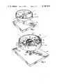
- FIG. 2is a perspective view illustrating the application of the differential drive to the gimbal structure of FIG. 1.
- FIG. 3is a top plan view of the structure of FIG. 2.
- FIG. 4is a sectional view taken on line 4--4 of FIG. 3.
- FIG. 5is a view similar to a portion of FIG. 4, showing an alternate idler arrangement.
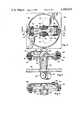
- FIG. 6is a side elevation view of the unit showing one drive cable motion.
- FIG. 7is a view taken on line 7--7 of FIG. 6.
- FIGS. 8 and 9are similar to FIGS. 6 and 7, respectively, but show another drive cable motion.
- FIG. 10is a top plan view of an alternative gear drive mechanism.
- FIG. 11is a sectional view taken on line 11--11 of FIG. 10.
- FIG. 1 of the drawingthere is illustrated a basic pedestal gimbal with drive structure omitted, designated generally by the numeral 10 and comprising a base 12 having a post or pedestal 14 secured at one end to the base 12 and having a fork or yoke 15 at the other end.
- a shaft 16is mounted for pivotal movement about a first axis corresponding to the bearings of the yoke and pivotally supporting a ring or platform mounting ring 18 for pivotal movement about a second axis corresponding to the axis of the shaft 16.
- Thisis a pedestal gimbal type structure showing a somewhat standard configuration, which normally supports a sensing platform, such as a radar antenna or the like.
- FIG. 2there is illustrated a support gimbal structure somewhat similar to the FIG. 1 embodiment having a differential drive in accordance with the invention applied thereto.
- a gimbal structure designated generally by the numerals 20includes a base mounting member 22 having a post or pedestal 24 secured at one end to the base 22 and extending upward therefrom.
- a yoke 26 having separate spaced apart parallel legsincludes bearing means for supporting a pivot shaft 30, on which is pivotally mounted a cross shaft 32.
- the cross shaft 32is pivotally mounted on the support or pivot shaft 30 for pivotal motion about the axis of the shaft 30.
- the cross shaft 32includes bearing journals at 34 and 36 for pivotally supporting a platform ring 38 for pivotal movement about the cross shaft longitudinal axis. This mounting arrangement permits the platform ring 38 to pivot in substantially any one of the directions within a hemisphere.
- the drive mechanism or assemblyincludes first and second reversible drive motors 40 and 42 having respective drive pulleys 44 and 46. These drive pulleys are connected by means of a drive cable or belt 48 to a pair of driven members or pulleys 50 and 62 which are fixed non-rotatably to the platform ring 38. While a drive cable is illustrated and described it should be understood that any suitable flexible drive member can be used such as a belt, chain, etc. Driven pulleys 50 and 62 are connected to the ring 38 and rotate therewith about the axis of the cross shaft 32.
- the endless belt or cable 48may be secured to one or both of the driven pulleys 50 and 62 by a clamp or the like such as shown at 52.
- the cable 48is termed an endless cable, although it may have two ends terminating at substantially the same place and connected to the pulley 50 and/or 62. The cable may not be truly endless in the technical sense, but may actually be one or two cables.
- the cablebeginning at the driven pulley 50, trails over a first idler 54 adjacent the driven pulley 50, a second idler 56 journaled for rotation about pivot shaft 30, then under drive pulley 44 on motor 40 and then up over another idler pulley 58 which is mounted on shaft 30 adjacent to and concentric with idler 56.
- the cablethen passes under idler 60, up and over driven pulley 62, the cable continuing under idler 64 and back up over idler 68, which is journaled on pivot shaft 30, down and around drive pulley 46 on motor 42 and up over idler pulley 70, adjacent and concentric with pulley 68, across idler pulley 72, and thence back to the driven pulley 50.
- Idler pulleys 54 and 72are mounted above one end of cross shaft 32 and idler pulleys 60 and 64 are mounted below the other end of the cross shaft.
- the pivot of the ring 38is established by the relative driving of the two motors 40 and 42. These motors may be driven simultaneously in the same direction or in opposite directions.
- the operation of the differential gimbal drive of the inventioncan best be understood by describing two special cases.
- the first case, illustrated in FIGS. 6 and 7,is pure cross shaft motion with no motion of the sensor platform or ring 38 relative to the cross shaft 32.
- both motorsare driven in the same direction as shown by the arrows at the same speed. This would result in rotation of the cross shaft in a positive direction as indicated about its pivot shaft 30, with no motion of the ring 38 relative to the cross shaft 32.
- both motorsare driven in a direction opposite one another at the same speed, as in FIGS. 8 and 9. This results in rotation of the platform or ring 38, but the cross shaft 32 remains stationary relative to the pivot shaft 30.
- Compounded gimbal motionresults from differential motor operation.
- the motorsmay be operated in the same direction at different speeds, or in different directions at different speeds, resulting in compound motion.
- the compound motioncan be used simply to orient the platform in a particular direction or to sweep the sensing platform for scanning.
- FIG. 5the modification shown therein utilizes a single idler pulley 84 in place of three pulleys 60, 62 and 64 of the previously described embodiment.
- This embodimentincludes a pedestal 74 having a yoke mounting of a cross shaft 76 with a ring 78 pivotally mounted on the axis thereof.
- a drive cable 80extends around and is secured to the driven pulley 82 secured to ring 78, around idler pulleys as in the previous embodiment, and around a single idler pulley 84 mounted such as by a screw or journal member 86 on the cross shaft 76.
- the operation of the assemblyis essentially the same.
- a platform base member 88includes a vertically extending post 90 which includes a yoke on which is pivotally mounted a cross shaft 92 and which in turn mounts a gimbal ring or platform ring 94.
- a driven gear 96 of the bevel typeis coupled directly to the ring 94 for rotation with the ring about the axis of the cross shaft 92.
- a pair of bevelled gears 98 and 100are pivotally or rotatably mounted on the yoke shaft 102 to mesh with gear 96 and are connected by link members 104 and 106, respectively, to a pair of separate reversible drive motors 108 and 110.
Landscapes
- Variable-Direction Aerials And Aerial Arrays (AREA)
Abstract
Description
Claims (10)
Priority Applications (1)
| Application Number | Priority Date | Filing Date | Title |
|---|---|---|---|
| US06/251,402US4396919A (en) | 1981-04-06 | 1981-04-06 | Differential drive pedestal gimbal |
Applications Claiming Priority (1)
| Application Number | Priority Date | Filing Date | Title |
|---|---|---|---|
| US06/251,402US4396919A (en) | 1981-04-06 | 1981-04-06 | Differential drive pedestal gimbal |
Publications (1)
| Publication Number | Publication Date |
|---|---|
| US4396919Atrue US4396919A (en) | 1983-08-02 |
Family
ID=22951818
Family Applications (1)
| Application Number | Title | Priority Date | Filing Date |
|---|---|---|---|
| US06/251,402Expired - LifetimeUS4396919A (en) | 1981-04-06 | 1981-04-06 | Differential drive pedestal gimbal |
Country Status (1)
| Country | Link |
|---|---|
| US (1) | US4396919A (en) |
Cited By (23)
| Publication number | Priority date | Publication date | Assignee | Title |
|---|---|---|---|---|
| US4512448A (en)* | 1981-09-25 | 1985-04-23 | Thomson-Csf | System for equilibrating an imbalance couple and use of such a system for equilibrating an airborne radar antenna |
| EP0140551A1 (en)* | 1983-10-03 | 1985-05-08 | General Motors Corporation | Adjustment mechanism |
| US4580461A (en)* | 1983-03-31 | 1986-04-08 | Ball Corporation | Biax gimbal arrangement |
| US4616906A (en)* | 1983-10-03 | 1986-10-14 | General Motor Corporation | Adjustment mechanism |
| US4692771A (en)* | 1985-03-28 | 1987-09-08 | Satellite Technology Services, Inc. | Antenna dish reflector with integral azimuth track |
| US4716416A (en)* | 1985-03-28 | 1987-12-29 | Satellite Technology Services, Inc. | Antenna dish reflector with integral declination adjustment |
| US5279479A (en)* | 1990-10-15 | 1994-01-18 | Hughes Missile Systems Company | Advanced seeker with large look angle |
| FR2696046A1 (en)* | 1992-09-14 | 1994-03-25 | Cal Corp | Antenna pointing mechanism. |
| FR2761286A1 (en)* | 1997-03-31 | 1998-10-02 | Hughes Electronics Corp | MULTI-AXIS POSITIONER |
| US6285339B1 (en) | 2000-04-07 | 2001-09-04 | L-3 Communications Corporation | Two axis positioner with zero backlash |
| US6326759B1 (en)* | 2000-09-05 | 2001-12-04 | The United States Of America As Represented By The Secretary Of The Navy | Ball joint gimbal system |
| US6396233B1 (en)* | 2000-09-05 | 2002-05-28 | The United States Of America As Represented By The Secretary Of The Navy | Ball joint gimbal system |
| US20070019330A1 (en)* | 2005-07-12 | 2007-01-25 | Charles Wolfersberger | Apparatus for pivotally orienting a projection device |
| US20070089557A1 (en)* | 2004-09-30 | 2007-04-26 | Solomon Todd R | Multi-ply strap drive trains for robotic arms |
| US20080021440A1 (en)* | 2004-09-30 | 2008-01-24 | Solomon Todd R | Electro-mechancial strap stack in robotic arms |
| US20120024185A1 (en)* | 2010-07-27 | 2012-02-02 | Raytheon Company | Projectile that includes a gimbal stop |
| US20120316017A1 (en)* | 2009-12-15 | 2012-12-13 | Dotan Ltd. | Orientation system and method |
| US20150027249A1 (en)* | 2013-07-25 | 2015-01-29 | Liftwave, Inc. Dba Rise Robotics | Differential conical drive |
| DE102011082008B4 (en) | 2011-09-01 | 2018-03-01 | Rohde & Schwarz Gmbh & Co. Kg | Device for positioning a measurement object |
| CN109417227A (en)* | 2016-06-30 | 2019-03-01 | 鹰联电子科技有限公司 | Can Two axle drive antenna installation base unit |
| EP3508158A4 (en)* | 2016-08-31 | 2019-09-04 | Microport (Shanghai) Medbot Co., Ltd. | SET OF INSTRUMENTS AND OPERATING INSTRUMENT |
| US10449011B2 (en) | 2004-09-30 | 2019-10-22 | Intuitive Surgical Operations, Inc. | Offset remote center manipulator for robotic surgery |
| US12374773B2 (en)* | 2020-01-09 | 2025-07-29 | Space Exploration Technologies Corp. | Pan/tilt assembly for antenna apparatus |
Citations (8)
| Publication number | Priority date | Publication date | Assignee | Title |
|---|---|---|---|---|
| US1694477A (en)* | 1921-04-02 | 1928-12-11 | George William H Long | Dirigible mounting and control mechanism therefor |
| US1733531A (en)* | 1929-10-29 | Sight-contkolled gunnery system | ||
| US2512636A (en)* | 1946-08-28 | 1950-06-27 | Gen Electric | Semicircular type support and drive for receiver parabola stabilization |
| US2530890A (en)* | 1947-07-26 | 1950-11-21 | Bell Telephone Labor Inc | Radar antenna driving mechanism |
| US2654031A (en)* | 1950-03-27 | 1953-09-29 | North American Aviation Inc | Antenna mount |
| FR1112116A (en)* | 1953-09-02 | 1956-03-08 | Savage & Parsons Ltd | System for moving a device such as a radar detector around two perpendicular axes |
| US3987453A (en)* | 1975-08-18 | 1976-10-19 | The United States Of America As Represented By The Secretary Of The Air Force | Balanced exciter for wideband antenna element |
| US4014026A (en)* | 1975-11-25 | 1977-03-22 | Westinghouse Electric Corporation | Power operated antenna assembly |
- 1981
- 1981-04-06USUS06/251,402patent/US4396919A/ennot_activeExpired - Lifetime
Patent Citations (8)
| Publication number | Priority date | Publication date | Assignee | Title |
|---|---|---|---|---|
| US1733531A (en)* | 1929-10-29 | Sight-contkolled gunnery system | ||
| US1694477A (en)* | 1921-04-02 | 1928-12-11 | George William H Long | Dirigible mounting and control mechanism therefor |
| US2512636A (en)* | 1946-08-28 | 1950-06-27 | Gen Electric | Semicircular type support and drive for receiver parabola stabilization |
| US2530890A (en)* | 1947-07-26 | 1950-11-21 | Bell Telephone Labor Inc | Radar antenna driving mechanism |
| US2654031A (en)* | 1950-03-27 | 1953-09-29 | North American Aviation Inc | Antenna mount |
| FR1112116A (en)* | 1953-09-02 | 1956-03-08 | Savage & Parsons Ltd | System for moving a device such as a radar detector around two perpendicular axes |
| US3987453A (en)* | 1975-08-18 | 1976-10-19 | The United States Of America As Represented By The Secretary Of The Air Force | Balanced exciter for wideband antenna element |
| US4014026A (en)* | 1975-11-25 | 1977-03-22 | Westinghouse Electric Corporation | Power operated antenna assembly |
Cited By (39)
| Publication number | Priority date | Publication date | Assignee | Title |
|---|---|---|---|---|
| US4512448A (en)* | 1981-09-25 | 1985-04-23 | Thomson-Csf | System for equilibrating an imbalance couple and use of such a system for equilibrating an airborne radar antenna |
| US4580461A (en)* | 1983-03-31 | 1986-04-08 | Ball Corporation | Biax gimbal arrangement |
| EP0140551A1 (en)* | 1983-10-03 | 1985-05-08 | General Motors Corporation | Adjustment mechanism |
| US4616906A (en)* | 1983-10-03 | 1986-10-14 | General Motor Corporation | Adjustment mechanism |
| US4692771A (en)* | 1985-03-28 | 1987-09-08 | Satellite Technology Services, Inc. | Antenna dish reflector with integral azimuth track |
| US4716416A (en)* | 1985-03-28 | 1987-12-29 | Satellite Technology Services, Inc. | Antenna dish reflector with integral declination adjustment |
| US5279479A (en)* | 1990-10-15 | 1994-01-18 | Hughes Missile Systems Company | Advanced seeker with large look angle |
| FR2696046A1 (en)* | 1992-09-14 | 1994-03-25 | Cal Corp | Antenna pointing mechanism. |
| FR2761286A1 (en)* | 1997-03-31 | 1998-10-02 | Hughes Electronics Corp | MULTI-AXIS POSITIONER |
| US6285339B1 (en) | 2000-04-07 | 2001-09-04 | L-3 Communications Corporation | Two axis positioner with zero backlash |
| US6326759B1 (en)* | 2000-09-05 | 2001-12-04 | The United States Of America As Represented By The Secretary Of The Navy | Ball joint gimbal system |
| US6396233B1 (en)* | 2000-09-05 | 2002-05-28 | The United States Of America As Represented By The Secretary Of The Navy | Ball joint gimbal system |
| US9803727B2 (en) | 2004-09-30 | 2017-10-31 | Intuitive Surgical Operations, Inc. | Strap guide system and methods thereof for robotic surgical arms |
| US20070089557A1 (en)* | 2004-09-30 | 2007-04-26 | Solomon Todd R | Multi-ply strap drive trains for robotic arms |
| US20080021440A1 (en)* | 2004-09-30 | 2008-01-24 | Solomon Todd R | Electro-mechancial strap stack in robotic arms |
| US10595948B2 (en) | 2004-09-30 | 2020-03-24 | Intuitive Surgical Operations, Inc. | Methods and apparatus for stacked electro-mechancial straps in robotic arms |
| US9797484B2 (en) | 2004-09-30 | 2017-10-24 | Intuitive Surgical Operations, Inc. | Methods for robotic arms with strap drive trains |
| US10449011B2 (en) | 2004-09-30 | 2019-10-22 | Intuitive Surgical Operations, Inc. | Offset remote center manipulator for robotic surgery |
| US9261172B2 (en)* | 2004-09-30 | 2016-02-16 | Intuitive Surgical Operations, Inc. | Multi-ply strap drive trains for surgical robotic arms |
| US20130239735A1 (en)* | 2004-09-30 | 2013-09-19 | Intuitive Surgical Operations, Inc. | Multi-Ply Strap Drive Trains for Robotic Arms |
| US10646292B2 (en) | 2004-09-30 | 2020-05-12 | Intuitive Surgical Operations, Inc. | Electro-mechanical strap stack in robotic arms |
| US11160626B2 (en) | 2004-09-30 | 2021-11-02 | Intuitive Surgical Operations, Inc. | Offset remote center manipulator for robotic surgery |
| US9068628B2 (en)* | 2004-09-30 | 2015-06-30 | Intuitive Surgical Operations, Inc. | Robotic arms with strap drive trains |
| US20070019330A1 (en)* | 2005-07-12 | 2007-01-25 | Charles Wolfersberger | Apparatus for pivotally orienting a projection device |
| US7690619B2 (en)* | 2005-07-12 | 2010-04-06 | Stereotaxis, Inc. | Apparatus for pivotally orienting a projection device |
| US8651987B2 (en)* | 2009-12-15 | 2014-02-18 | Dotan Ltd. | Orientation system and method |
| US20120316017A1 (en)* | 2009-12-15 | 2012-12-13 | Dotan Ltd. | Orientation system and method |
| US8375861B2 (en)* | 2010-07-27 | 2013-02-19 | Raytheon Company | Projectile that includes a gimbal stop |
| US20120024185A1 (en)* | 2010-07-27 | 2012-02-02 | Raytheon Company | Projectile that includes a gimbal stop |
| DE102011082008B4 (en) | 2011-09-01 | 2018-03-01 | Rohde & Schwarz Gmbh & Co. Kg | Device for positioning a measurement object |
| US20160091065A1 (en)* | 2013-07-25 | 2016-03-31 | Liftwave, Inc. Dba Rise Robotics | Differential conical drive |
| US9982762B2 (en)* | 2013-07-25 | 2018-05-29 | Liftwave, Inc. | Differential conical drive |
| US9121481B2 (en)* | 2013-07-25 | 2015-09-01 | Liftwave, Inc. | Differential conical drive |
| US20150027249A1 (en)* | 2013-07-25 | 2015-01-29 | Liftwave, Inc. Dba Rise Robotics | Differential conical drive |
| CN109417227A (en)* | 2016-06-30 | 2019-03-01 | 鹰联电子科技有限公司 | Can Two axle drive antenna installation base unit |
| EP3480889A4 (en)* | 2016-06-30 | 2020-02-19 | Intellian Technologies Inc. | Pedestal apparatus having antenna attached thereto capable of biaxial motion |
| US10957976B2 (en) | 2016-06-30 | 2021-03-23 | Intellian Technologies, Inc. | Pedestal apparatus having antenna attached thereto capable of biaxial motion |
| EP3508158A4 (en)* | 2016-08-31 | 2019-09-04 | Microport (Shanghai) Medbot Co., Ltd. | SET OF INSTRUMENTS AND OPERATING INSTRUMENT |
| US12374773B2 (en)* | 2020-01-09 | 2025-07-29 | Space Exploration Technologies Corp. | Pan/tilt assembly for antenna apparatus |
Similar Documents
| Publication | Publication Date | Title |
|---|---|---|
| US4396919A (en) | Differential drive pedestal gimbal | |
| US4282529A (en) | Differential drive rolling arc gimbal | |
| US6331138B1 (en) | Grinding machine | |
| US3999184A (en) | Satellite tracking antenna apparatus | |
| US4392140A (en) | Dual cable drive rolling arc gimbal | |
| US4204214A (en) | Slewing and tracking mechanism for dish structure | |
| US4546233A (en) | Robot arm having bearing support | |
| CA2047282A1 (en) | Attitude control device and drilling-direction control device | |
| CA2071269A1 (en) | Antenna with offset arrays and dual axis rotation | |
| DK0434915T3 (en) | Helical Angle Drive | |
| US4608884A (en) | Apparatus for driving two axes of the hand element of an industrial robot | |
| US4580461A (en) | Biax gimbal arrangement | |
| ES2013049A6 (en) | Rolling ball assembly and deck. | |
| CA1075058A (en) | Electrically controlled rear-view mirror | |
| CA2099654A1 (en) | Antenna Pointing Mechanism | |
| US4620830A (en) | Joint type robot | |
| GB2274176A (en) | Camera pedestals | |
| GB1568248A (en) | Manipulator arm including a drive unit | |
| US4465233A (en) | Spraying device, particularly for treatment of plants | |
| JPH09214235A (en) | Antenna directing device | |
| DE69002541D1 (en) | MOWER. | |
| DE2720421C2 (en) | Pivoting mirror arrangement | |
| GB1377868A (en) | Sediment-raking device for sedimentation apparatus | |
| KR970001660B1 (en) | Vertical Articulated Robot | |
| SU730548A2 (en) | Article-abrading apparatus |
Legal Events
| Date | Code | Title | Description |
|---|---|---|---|
| AS | Assignment | Owner name:GENERAL DYNAMICS CORPORATION, (POMONA DIVISION), P Free format text:ASSIGNMENT OF ASSIGNORS INTEREST.;ASSIGNOR:SPEICHER JOHN M.;REEL/FRAME:003876/0730 Effective date:19810401 | |
| STCF | Information on status: patent grant | Free format text:PATENTED CASE | |
| MAFP | Maintenance fee payment | Free format text:PAYMENT OF MAINTENANCE FEE, 4TH YEAR, PL 96-517 (ORIGINAL EVENT CODE: M170); ENTITY STATUS OF PATENT OWNER: LARGE ENTITY Year of fee payment:4 | |
| MAFP | Maintenance fee payment | Free format text:PAYMENT OF MAINTENANCE FEE, 8TH YEAR, PL 96-517 (ORIGINAL EVENT CODE: M171); ENTITY STATUS OF PATENT OWNER: LARGE ENTITY Year of fee payment:8 | |
| AS | Assignment | Owner name:HUGHES MISSILE SYSTEMS COMPANY, CALIFORNIA Free format text:ASSIGNMENT OF ASSIGNORS INTEREST.;ASSIGNOR:GENERAL DYNAMICS CORPORATION;REEL/FRAME:006279/0578 Effective date:19920820 | |
| MAFP | Maintenance fee payment | Free format text:PAYMENT OF MAINTENANCE FEE, 12TH YEAR, LARGE ENTITY (ORIGINAL EVENT CODE: M185); ENTITY STATUS OF PATENT OWNER: LARGE ENTITY Year of fee payment:12 | |
| FEPP | Fee payment procedure | Free format text:PAYOR NUMBER ASSIGNED (ORIGINAL EVENT CODE: ASPN); ENTITY STATUS OF PATENT OWNER: LARGE ENTITY |