US4396262A - Hand held transparency projector with simple advance mechanism - Google Patents
Hand held transparency projector with simple advance mechanismDownload PDFInfo
- Publication number
- US4396262A US4396262AUS06/325,577US32557781AUS4396262AUS 4396262 AUS4396262 AUS 4396262AUS 32557781 AUS32557781 AUS 32557781AUS 4396262 AUS4396262 AUS 4396262A
- Authority
- US
- United States
- Prior art keywords
- film
- cartridge
- housing
- advancing
- aperture
- Prior art date
- Legal status (The legal status is an assumption and is not a legal conclusion. Google has not performed a legal analysis and makes no representation as to the accuracy of the status listed.)
- Expired - Lifetime
Links
Images


Classifications
- G—PHYSICS
- G03—PHOTOGRAPHY; CINEMATOGRAPHY; ANALOGOUS TECHNIQUES USING WAVES OTHER THAN OPTICAL WAVES; ELECTROGRAPHY; HOLOGRAPHY
- G03B—APPARATUS OR ARRANGEMENTS FOR TAKING PHOTOGRAPHS OR FOR PROJECTING OR VIEWING THEM; APPARATUS OR ARRANGEMENTS EMPLOYING ANALOGOUS TECHNIQUES USING WAVES OTHER THAN OPTICAL WAVES; ACCESSORIES THEREFOR
- G03B21/00—Projectors or projection-type viewers; Accessories therefor
Definitions
- the present inventionrelates generally to still projection devices and more particularly to a hand-held projection device which is adapted for projection of pictures from a film strip housed within a cartridge.
- the object of this inventionis to overcome the above deficiencies without sacrificing quality or dependability. It is intended to provide a rugged, simple mechanism of few parts, high reliability and low manufacturing cost.
- a more specific oobject of the present inventionis to provide a hand-held projector which has a drive mechanism capable of intermittently advancing the film at a speed determined by the operator of the projector.
- a further specific object of the inventionis to provide a hand-held projector which includes a film driving claw for engaging and advancing the film in a cartridge in discrete linear steps.
- a still further object of the present inventionis to provide a projector of the type in which the film is driven by a manual hand operation which is easy to use, minimizes eye discomfort, is relatively noiseless, and is relatively inexpensive to manufacture.
- a hand-held projectorwhich includes a housing, a recess formed in one side of the housing for receiving a film cartridge, a projection aperture in the housing through which images on the film within the cartridge can be projected when the cartridge is positioned within the recess.
- a film driving meansis carried within the housing for engaging and advancing the film past the projecting aperture.
- the housingcomprises means for supporting at least one battery within the housing, actuating means for selectively connecting the battery for selective energization of a projection light source.
- a claw within the housingis positioned to engage perforations in the film of the cartridge when the cartridge is placed in the recess of the housing.
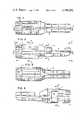
- FIG. 1is a top plan view of the projector
- FIG. 2is a left side elevational view of the projector shown in FIG. 1;
- FIG. 3is a bottom plan view of the projector shown in FIG. 1;
- FIG. 4is a right side elevational view of the projector and cartridge shown in FIG. 1;
- FIG. 5is a exploded perspective view of the cartridge
- FIG. 6is a rear view of the projector of FIG. 1;
- FIG. 7is a front view of the projector shown in FIG. 1;
- FIG. 8is a sectional view taken along lines 8--8 of FIG. 2;
- FIG. 9is a sectional view taken along lines 9--9 of FIG. 1;
- FIG. 10is a sectional veiw taken along lines 10--10 in FIG. 2;
- FIG. 11is a sectional veiw taken along lines 11--11 of FIG. 10;
- FIG. 12is a enlarged sectional view taken along lines 12--12 of FIG. 9;
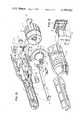
- FIG. 13is an exploded perspective view of the projector shown in FIG. 1 illustrating each of the various elements thereof;
- FIG. 14is a sectional view taken along lines 14--14 in FIG. 2;
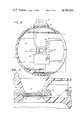
- FIG. 15is a front side view of the film cartridge with cover cut-away
- FIG. 16is a sectional view taken along lines 16--16 of FIG. 15 with cover in place;
- FIG. 17is a sectional view taken along lines 17--17 of FIG. 1;
- FIG. 18is a sectional view taken along lines 18--18 of FIG. 17;
- FIG. 19is a sectional view taken along lines 19--19 of FIG. 4.
- FIG. 13shows housing 1 which contains battery compartment 2 with battery contact strip 3 secured to the battery compartment 2.
- Battery strip 3has a spring end 4 for holding the base of a battery.
- contact tip 34On the other end of battery strip 3 is contact tip 34 which makes resilient contact with bulb contact 5.
- Button 31is in slideable contact with housing 1 and strip 3 having a first position where there is no electrical contact between strip 3 and bulb 6 and a second position which activates battery strip 3 so that tip 34 makes contact with bulb contact 5 to send electric current from the battery in battery compartment 2 to bulb 6.
- Bulb 6is housed in reflector 7 by means of bulb 6 being pressed into cutout 38 and into interference fit with collar 39 for secure placement.
- Transparent shield 103is placed between reflector 7 and cartridge 13 such that parts from breakage of bulb 6 cannot fall out.
- reflector 7reflects light to lens system 8 which includes lens 42 and lens 45 and is housed in focus housing 9.
- lens system 8which includes lens 42 and lens 45 and is housed in focus housing 9.
- film drive 10Located between reflector surface 7 and housing 9 containing lens system 8 is film drive 10.
- Film drive 10contains aperture 11 allowing transmission of light from bulb 6 through lens system 8 onto any surface along the axis formed by the line through bulb 6 and lens system 8.
- cartridge spring 12housed in housing 1 is cartridge spring 12 which secures cartridge 13 in place when cartridge 13 is inserted in opening 15 of housing 1.
- film 16is located perpendicular to the axis formed by a line drawn through the center of bulb 6 and lens system 8 as well as being adjacent to aperture 11 when actuator 10 is in its normal postion (projection mode).
- cartridge coveris cammed by protrusions 20 away from advance claw 17. In this manner advance claw 17 is protected from breakage as cartridge 13 is being installed.
- protrusions 20engage guide notches 21 (FIG. 15) in cartridge 13 the cartridge moves toward actuator 10 by the force imposed by cartridge spring 12, thereby locating cartridge.
- aperture 11is housed in a raised tapered rectangular Boss 100.
- advance claw 17which is tapered such that it comes out of contact with perforations 18 when actuator 10 is depressed and makes contact with perforations 18 of film 16 when actuator or push means 10 is released.
- the depressing movement of the actuatormay be referred to as the positioning stroke and the releasing movement as the film advancing return stroke of the actuator.
- film claw 17advances film 16 through perforations 18 one frame at a time each time actuator 10 is released after depressing.
- spring 19mounted on actuator 10 is spring 19 which holds actuator 10 against housing 1 and is resilient such that actuator 10 may be depressed in relation to housing 1 in order to have film advance claw 17 move film 16 one frame.
- actuator 10Located on actuator 10 as shown in FIG. 13 are guide protrusions 20 which mate with guide notches 21 of cartridge 13 as shown in FIG. 15.
- the protrusions 20 and notches 21retain actuator aperture 11 in slidable alignment with the frames of film 16 so that each frame is in alignment with the axis formed by a line drawn through the center of lens system 8 and bulb 6.
- Alignment of actuator 10 in relation to housing 1is provided by spring arms 22 being integral with actuator 10 for slideable contact along the inner surface 23 of housing 1, as shown in FIG. 14, the resilient nature of said arms 22 maintaining actuator 10 in slideable contact with cartridge 13 when cartridge 13 is inserted into housing 1.
- Film advance claw 17has access to film 16 and perforations 18 through cartridge aperture 24 as shown in FIG. 16.
- cartridge aperture 24 when placed in housing 1has the same axis as aperture 11 when spring 19 maintains actuator 10 in its normal position.
- the aperture 24is sized such that the perforations of the film strip are exposed to the advance claw 17, thereby to enable such claw to make contact with and engage such perforations to advance the film frame by frame on each advancing stroke of the push means 16.
- pin 27Located on lenss housing 9 is pin 27 which mates in slideable contact with slot 26 on the inner wall of housing 1. Since slot 26 is on an angle it allows lens housing 9 to move forward and backward within housing 1 to adjust the focus of the projected image as it is being passed from the lens system 8 to its point of viewing.
- film 16is placed in cartridge 13 such that there is no surface contact between the pictures located in frames 28 on film 16 and the cartridge housing 13 to prevent scratching of the images on film 16. This is accomplished by having the position of continuous loop film 16 that is to be presently viewed parallel to the surface of cartridge 13 that contains cartridge aperture 24 while having the rest of the loop 16 being angled as it is located in cartridge 13 between the side containing aperture 24 and the opposite side of the cartridge 13, as shown in FIG. 15.
Landscapes
- Physics & Mathematics (AREA)
- General Physics & Mathematics (AREA)
- Projection Apparatus (AREA)
Abstract
Description
Claims (7)
Priority Applications (1)
| Application Number | Priority Date | Filing Date | Title |
|---|---|---|---|
| US06/325,577US4396262A (en) | 1980-01-25 | 1981-11-30 | Hand held transparency projector with simple advance mechanism |
Applications Claiming Priority (2)
| Application Number | Priority Date | Filing Date | Title |
|---|---|---|---|
| US11558180A | 1980-01-25 | 1980-01-25 | |
| US06/325,577US4396262A (en) | 1980-01-25 | 1981-11-30 | Hand held transparency projector with simple advance mechanism |
Related Parent Applications (1)
| Application Number | Title | Priority Date | Filing Date |
|---|---|---|---|
| US11558180AContinuation | 1980-01-25 | 1980-01-25 |
Publications (1)
| Publication Number | Publication Date |
|---|---|
| US4396262Atrue US4396262A (en) | 1983-08-02 |
Family
ID=26813352
Family Applications (1)
| Application Number | Title | Priority Date | Filing Date |
|---|---|---|---|
| US06/325,577Expired - LifetimeUS4396262A (en) | 1980-01-25 | 1981-11-30 | Hand held transparency projector with simple advance mechanism |
Country Status (1)
| Country | Link |
|---|---|
| US (1) | US4396262A (en) |
Cited By (5)
| Publication number | Priority date | Publication date | Assignee | Title |
|---|---|---|---|---|
| US5914356A (en)* | 1996-12-06 | 1999-06-22 | Orthovita, Inc. | Bioactive load bearing bone bonding compositions |
| US20030030622A1 (en)* | 2001-04-18 | 2003-02-13 | Jani Vaarala | Presentation of images |
| US6623124B2 (en)* | 2000-05-16 | 2003-09-23 | Hal Corporation | Projection type illuminating device |
| US20080036923A1 (en)* | 2006-08-11 | 2008-02-14 | Canon Kabushiki Kaisha | Handy image projection apparatus |
| US10884167B2 (en)* | 2018-07-17 | 2021-01-05 | Clifford Newman | Handheld projector and gaming aid for tabletop grid mat |
Citations (13)
| Publication number | Priority date | Publication date | Assignee | Title |
|---|---|---|---|---|
| US1814588A (en)* | 1927-05-14 | 1931-07-14 | For Visual Education Inc Soc | Picture projector |
| US2100008A (en)* | 1936-06-08 | 1937-11-23 | Clarence L Stephens | Picture projecting device |
| US2146237A (en)* | 1937-08-02 | 1939-02-07 | Stephens Products Co Inc | Picture projecting device |
| US2583510A (en)* | 1948-06-14 | 1952-01-22 | Frederick B Ingram | Picture viewing device |
| US2764058A (en)* | 1952-11-01 | 1956-09-25 | American Optical Corp | Portable combined photographic slide viewing and projecting device |
| US3218745A (en)* | 1962-11-30 | 1965-11-23 | Sawyer S Inc | Photographic toy gun |
| US3466123A (en)* | 1967-07-13 | 1969-09-09 | Audiscan Corp | Film projection cartridge |
| GB1262048A (en) | 1969-05-24 | 1972-02-02 | Walker Pen Spa | Endless-film viewer |
| GB1325034A (en) | 1969-10-17 | 1973-08-01 | Fjl Corp | Motion picture viewer with removable cartridge |
| US3801199A (en)* | 1972-01-10 | 1974-04-02 | R Kaye | Image projection system with filmstrip cassette |
| DE2415875A1 (en) | 1973-04-03 | 1974-10-17 | Lazarus | IMAGE PROJECTOR AND VIEWER |
| US4059351A (en)* | 1976-10-15 | 1977-11-22 | Wisotsky Harry A | Hand-held film projectors |
| US4185899A (en)* | 1973-10-29 | 1980-01-29 | Action Films, Inc. | Combination viewer and projector |
- 1981
- 1981-11-30USUS06/325,577patent/US4396262A/ennot_activeExpired - Lifetime
Patent Citations (13)
| Publication number | Priority date | Publication date | Assignee | Title |
|---|---|---|---|---|
| US1814588A (en)* | 1927-05-14 | 1931-07-14 | For Visual Education Inc Soc | Picture projector |
| US2100008A (en)* | 1936-06-08 | 1937-11-23 | Clarence L Stephens | Picture projecting device |
| US2146237A (en)* | 1937-08-02 | 1939-02-07 | Stephens Products Co Inc | Picture projecting device |
| US2583510A (en)* | 1948-06-14 | 1952-01-22 | Frederick B Ingram | Picture viewing device |
| US2764058A (en)* | 1952-11-01 | 1956-09-25 | American Optical Corp | Portable combined photographic slide viewing and projecting device |
| US3218745A (en)* | 1962-11-30 | 1965-11-23 | Sawyer S Inc | Photographic toy gun |
| US3466123A (en)* | 1967-07-13 | 1969-09-09 | Audiscan Corp | Film projection cartridge |
| GB1262048A (en) | 1969-05-24 | 1972-02-02 | Walker Pen Spa | Endless-film viewer |
| GB1325034A (en) | 1969-10-17 | 1973-08-01 | Fjl Corp | Motion picture viewer with removable cartridge |
| US3801199A (en)* | 1972-01-10 | 1974-04-02 | R Kaye | Image projection system with filmstrip cassette |
| DE2415875A1 (en) | 1973-04-03 | 1974-10-17 | Lazarus | IMAGE PROJECTOR AND VIEWER |
| US4185899A (en)* | 1973-10-29 | 1980-01-29 | Action Films, Inc. | Combination viewer and projector |
| US4059351A (en)* | 1976-10-15 | 1977-11-22 | Wisotsky Harry A | Hand-held film projectors |
Cited By (7)
| Publication number | Priority date | Publication date | Assignee | Title |
|---|---|---|---|---|
| US5914356A (en)* | 1996-12-06 | 1999-06-22 | Orthovita, Inc. | Bioactive load bearing bone bonding compositions |
| US6623124B2 (en)* | 2000-05-16 | 2003-09-23 | Hal Corporation | Projection type illuminating device |
| US20030030622A1 (en)* | 2001-04-18 | 2003-02-13 | Jani Vaarala | Presentation of images |
| US7134078B2 (en) | 2001-04-18 | 2006-11-07 | Nokia Corporation | Handheld portable user device and method for the presentation of images |
| US20080036923A1 (en)* | 2006-08-11 | 2008-02-14 | Canon Kabushiki Kaisha | Handy image projection apparatus |
| US7988299B2 (en)* | 2006-08-11 | 2011-08-02 | Canon Kabushiki Kaisha | Handy image projection apparatus |
| US10884167B2 (en)* | 2018-07-17 | 2021-01-05 | Clifford Newman | Handheld projector and gaming aid for tabletop grid mat |
Similar Documents
| Publication | Publication Date | Title |
|---|---|---|
| US5790907A (en) | Compact photographic camera having lens slide | |
| US5003330A (en) | Electronic flash and lens-fitted photographic film unit including the same | |
| US5170199A (en) | Lens-fitted photographic film unit | |
| US4491434A (en) | Handheld viewer for transparency film | |
| US4761675A (en) | Negative carrier assembly for use with a photographic printer | |
| US4396262A (en) | Hand held transparency projector with simple advance mechanism | |
| US4116533A (en) | Stereoscopic viewer | |
| US4059351A (en) | Hand-held film projectors | |
| US2534732A (en) | Film guide for stripfilm projectors | |
| EP0033360A1 (en) | Hand-held transparency projector with simple advance mechanism | |
| US4026636A (en) | Stereoscopic films | |
| US2326718A (en) | Stereoscope | |
| US2146237A (en) | Picture projecting device | |
| US2551482A (en) | Film viewing editor | |
| US3682076A (en) | Support member for preventing inverted insertion of a film cassette | |
| US2835176A (en) | Carrying case for photographic apparatus | |
| US3924941A (en) | Cassette and cassette holder for improved controlled-reading device | |
| US3749482A (en) | Motion picture film projector | |
| US4128320A (en) | Stereoscopic films and viewers therefor | |
| JPH10307320A (en) | Camera | |
| US6487373B2 (en) | Shutter release unit having multiple functions | |
| US4059352A (en) | Slide projector | |
| US3675556A (en) | Double exposure prevention system and camera | |
| US4077705A (en) | Motion picture projection apparatus | |
| US4145118A (en) | Viewing instrument |
Legal Events
| Date | Code | Title | Description |
|---|---|---|---|
| STCF | Information on status: patent grant | Free format text:PATENTED CASE | |
| AS | Assignment | Owner name:VIEW-MASTER INTERNATIONAL GROUP, INC. Free format text:ASSIGNMENT OF ASSIGNORS INTEREST.;ASSIGNOR:VIEW-MASTER INTERNATIONAL GROUP, A LIMITED PARTNERSHIP OF NY;REEL/FRAME:004197/0867 Effective date:19831026 | |
| CC | Certificate of correction | ||
| FEPP | Fee payment procedure | Free format text:PAYOR NUMBER ASSIGNED (ORIGINAL EVENT CODE: ASPN); ENTITY STATUS OF PATENT OWNER: LARGE ENTITY | |
| MAFP | Maintenance fee payment | Free format text:PAYMENT OF MAINTENANCE FEE, 4TH YEAR, PL 96-517 (ORIGINAL EVENT CODE: M170); ENTITY STATUS OF PATENT OWNER: LARGE ENTITY Year of fee payment:4 | |
| AS | Assignment | Owner name:MIDLANTIC NATIONAL BANK Free format text:SECURITY INTEREST;ASSIGNOR:VIEW-MASTER IDEAL GROUP, INC.;REEL/FRAME:005240/0060 Effective date:19890906 Owner name:MIDLANTIC NATIONAL BANK Free format text:SECURITY INTEREST;ASSIGNOR:VIEW-MASTER IDEAL GROUP, INC.;REEL/FRAME:005240/0039 Effective date:19890906 | |
| MAFP | Maintenance fee payment | Free format text:PAYMENT OF MAINTENANCE FEE, 8TH YEAR, PL 96-517 (ORIGINAL EVENT CODE: M171); ENTITY STATUS OF PATENT OWNER: LARGE ENTITY Year of fee payment:8 | |
| AS | Assignment | Owner name:MARINE MIDLAND BANK, N.A. Free format text:SECURITY INTEREST;ASSIGNOR:VIEW MASTER-IDEAL GROUP, INC.;REEL/FRAME:005853/0041 Effective date:19910731 Owner name:STANDARD CHARTERED BANK Free format text:SECURITY INTEREST;ASSIGNOR:VIEW MASTER-IDEAL GROUP, INC.;REEL/FRAME:005853/0041 Effective date:19910731 Owner name:BANK OF TOKYO TRUST COMPANY, THE Free format text:SECURITY INTEREST;ASSIGNOR:VIEW MASTER-IDEAL GROUP, INC.;REEL/FRAME:005853/0041 Effective date:19910731 Owner name:BANK OF NOVA SCOTIA, THE Free format text:SECURITY INTEREST;ASSIGNOR:VIEW MASTER-IDEAL GROUP, INC.;REEL/FRAME:005853/0041 Effective date:19910731 Owner name:MIDLANTIC NATIONAL BANK Free format text:SECURITY INTEREST;ASSIGNOR:VIEW MASTER-IDEAL GROUP, INC.;REEL/FRAME:005853/0041 Effective date:19910731 Owner name:MERIDIAN BANK Free format text:SECURITY INTEREST;ASSIGNOR:VIEW MASTER-IDEAL GROUP, INC.;REEL/FRAME:005853/0041 Effective date:19910731 Owner name:UNITED JERSEY BANK Free format text:SECURITY INTEREST;ASSIGNOR:VIEW MASTER-IDEAL GROUP, INC.;REEL/FRAME:005853/0041 Effective date:19910731 Owner name:PHILADELPHIA NATIONAL BANK Free format text:SECURITY INTEREST;ASSIGNOR:VIEW MASTER-IDEAL GROUP, INC.;REEL/FRAME:005853/0041 Effective date:19910731 Owner name:FIDELITY BANK, N.A. Free format text:SECURITY INTEREST;ASSIGNOR:VIEW MASTER-IDEAL GROUP, INC.;REEL/FRAME:005853/0041 Effective date:19910731 Owner name:NCNB NATIONAL BANK OF NORTH CAROLINA Free format text:SECURITY INTEREST;ASSIGNOR:VIEW MASTER-IDEAL GROUP, INC.;REEL/FRAME:005853/0041 Effective date:19910731 | |
| AS | Assignment | Owner name:NATIONSBANK OF NORTH CAROLINA, N.A. Free format text:SECURITY INTEREST;ASSIGNOR:TYCO INDUSTRIES, INC.;REEL/FRAME:006225/0964 Effective date:19920603 | |
| AS | Assignment | Owner name:VIEW-MASTER IDEAL GROUP, INC, NEW JERSEY Free format text:RELEASED BY SECURED PARTY;ASSIGNOR:MIDLANTIC NATIONAL BANK, AS AGENT;REEL/FRAME:006522/0015 Effective date:19920602 | |
| AS | Assignment | Owner name:TYCO INDUSTRIES, INC., NEW JERSEY Free format text:BY WAY OF EXPLANATION, "OLD" TYCO INDUSTRIES, INC. MERGED INTO TYCO INDUSTRIES II, INC. AND TYCO INDUSTRIES II, INC. CHANGED ITS NAME TO TYCO INDUSTRIES, INC.;ASSIGNOR:TYCO INDUSTRIES, INC.;REEL/FRAME:006744/0964 Effective date:19920601 Owner name:TYCO INDUSTRIES II, INC., NEW JERSEY Free format text:ASSIGNMENT OF ASSIGNORS INTEREST;ASSIGNOR:VIEW-MASTER IDEAL GROUP, INC.;REEL/FRAME:006732/0321 Effective date:19920601 | |
| MAFP | Maintenance fee payment | Free format text:PAYMENT OF MAINTENANCE FEE, 12TH YEAR, LARGE ENTITY (ORIGINAL EVENT CODE: M185); ENTITY STATUS OF PATENT OWNER: LARGE ENTITY Year of fee payment:12 | |
| FEPP | Fee payment procedure | Free format text:PAYOR NUMBER ASSIGNED (ORIGINAL EVENT CODE: ASPN); ENTITY STATUS OF PATENT OWNER: LARGE ENTITY Free format text:PAYER NUMBER DE-ASSIGNED (ORIGINAL EVENT CODE: RMPN); ENTITY STATUS OF PATENT OWNER: LARGE ENTITY | |
| AS | Assignment | Owner name:TYCO INDUSTRIES, INC., NEW JERSEY Free format text:RELEASE OF SECURITY INTEREST;ASSIGNOR:NATIONSBANK, N.A. (CAROLINAS), FORMERLY KNOWN AS NATIONSBANK OF NORTH CAROLINA, N.A., AS AGENT;REEL/FRAME:007363/0210 Effective date:19950224 Owner name:GENERAL ELECTRIC CAPITAL CORPORATION, AS AGENT, CO Free format text:ASSIGNMENT FOR SECURITY (PATENTS);ASSIGNOR:TYCO INDUSTRIES, INC.;REEL/FRAME:007363/0193 Effective date:19950224 |