US4396215A - Log grapple device - Google Patents
Log grapple deviceDownload PDFInfo
- Publication number
- US4396215A US4396215AUS06/295,344US29534481AUS4396215AUS 4396215 AUS4396215 AUS 4396215AUS 29534481 AUS29534481 AUS 29534481AUS 4396215 AUS4396215 AUS 4396215A
- Authority
- US
- United States
- Prior art keywords
- valve
- passage
- cylinder
- inlet
- unloader
- Prior art date
- Legal status (The legal status is an assumption and is not a legal conclusion. Google has not performed a legal analysis and makes no representation as to the accuracy of the status listed.)
- Expired - Fee Related
Links
Images

Classifications
- B—PERFORMING OPERATIONS; TRANSPORTING
- B66—HOISTING; LIFTING; HAULING
- B66C—CRANES; LOAD-ENGAGING ELEMENTS OR DEVICES FOR CRANES, CAPSTANS, WINCHES, OR TACKLES
- B66C3/00—Load-engaging elements or devices attached to lifting or lowering gear of cranes or adapted for connection therewith and intended primarily for transmitting lifting forces to loose materials; Grabs
- B66C3/14—Grabs opened or closed by driving motors thereon
- B66C3/16—Grabs opened or closed by driving motors thereon by fluid motors
Definitions
- the present inventionrelates to log grapples, and more particularly to a system for maintaining a squeezing force on a load of logs in a grapple independent of the main hydraulic system.
- a log grapplesuch as that shown in U.S. Pat. No. 3,620,394 a plurality of logs are gripped by the tongs of a grapple mechanism mounted on a skidder vehicle for transport from one location to another location for processing.
- theyare likely to shift within the grapple tongs, and unless means are provided to maintain pressure of the tongs against the logs, the logs are likely to slip out.
- it is also important that such meansnot require the continuous pumping of oil through the vehicle hydraulic system since this can cause overheating and undue wear of the pump and other hydraulic components.
- U.S. Pat. No. 3,854,766provides a system as described above which provides a hydraulic system including an accumulator and an unloader valve; however, the grapple control valve is located downstream of the unloader valve, and tests on such a system have shown that leakage around the control valve spool can be so high as to cause undue cycling of the unloader valve. While this condition can be avoided by the use of a closed center control valve, such valves are quite expensive.
- the present inventionprovides a system including an accumulator and an unloader valve which is downstream of the control valve and is thus independent of leakage in the control valve.
- an accumulatorwhich is downstream of the control valve and is thus independent of leakage in the control valve.
- the present inventionprovides a pilot check valve installed in parallel in the work line, and a check valve in the drain line from the unloader valve.
- the unloader valve, the pilot check valve and the check valveare incorporated in a single unit.
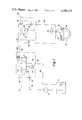
- FIG. 1is a schematic diagram of the hydraulic system of the present invention.
- FIG. 2is a cross-sectional view of the valve assembly of the present invention.
- FIG. 1there is illustrated a hydraulic system 10 for operating a log grapple device 12, comprising a reservoir 14, a pump 16, a control valve assembly 18, an unloader valve assembly 20, and an accumulator 22.
- control valve assembly 18comprises a conventional, manually-actuated, open center spool valve 24, and a relief valve 26.
- flow from the outlet of the pump 16is through a line 28 to an inlet port 30 in valve assembly 18, through an internal passage 32 through the open center of the valve and back to reservoir 14 via an internal passage 34 to drain port 36 and drain line 38.
- Relief valve 26is connected between internal passages 32 and 34.
- the unloader valve assemblycomprises a valve body 48, an inlet port 50, an outlet port 52, a drain port 54, a pilot valve unit 56 mounted on the body 48, a main poppet valve 58 within the body 48, a pilot check valve 60 within the body 48, and a drain check valve 62 within the body 48.
- the pilot valve unit 56 illustrated hereinis a portion of a Model 17-1-6 unloading valve manufactured by the Fluid Power Systems Division of AMBAC Industries and will not be described herein in detail.
- the pilot valve unit 56is mounted on the body 48 through an adapter plate 64 and includes a first chamber 66 which communicates with a bore 68 which intersects inlet passage 51 extending inward from the inlet port 50 and in which the main poppet 58 is located, a second chamber 70 which communicates with a bore 72 which intersects the outlet port 52 and in which the pilot check valve 60 is located.
- the main poppet valve 58comprises a poppet element 74 received in bore 68, a spacer 76 also received in bore 68, and a spring 78 acting between the poppet and the spacer to bias the poppet into the position shown, and the spacer into engagement with the adapter plate 64 which closes the open end of bore 68.
- a bore 77 coaxial with bore 68also intersects inlet passage 51, its intersection with passage 51 defining a valve seat for poppet element 74.
- the pilot check valve 60comprises a poppet element 80 received in the bore 72, a spring 82 acting between the poppet element and the adapter plate 64 which closes bore 72, pilot piston element 84 received in a bore 86 coaxial with the bore 72, and a pin 88 received in a hole formed in the end of piston 84 and in engagement with the poppet element 80.
- a washer 90is received beneath piston 84, and a plug 91 screwed into a hole formed in the body 48 closes the bore 86. Bore 86 communicates with the inlet passage 51 by means of a short, small-diameter bore 92 through which pin 88 extends.
- a bore 94 smaller in diameter than bore 72connects bore 72 and the inlet passage 51, the intersection of bore 72 and bore 94 defining a valve seat for the poppet element 80.
- the drain check valve 62comprises a poppet element 96 received in a bore 98 which intersects the drain port 54, a plug 100 which is screwed into a hole formed in the body 48 and which closes the bore 98, and a spring 104 received between the plug 100 and the poppet element 96.
- a bore 106connects bore 98 and bore 77, and its intersection with bore 98 defines a valve seat for poppet element 96.
- the unloading pressureis controlled by the pilot valve unit 56, which as noted above is a well-known commercially available unit.
- Inlet pressureis transmitted to the first chamber 66 via a bleed port 118 in poppet element 74, a passage 119 through the spacer 76, a passage 120 through adapter 64, a port 121 in the body of pilot unit 56, and internal ports 123 formed in piston element 122 of the pilot unit.
- This pressureis also transmitted to chamber 70 via bleed ports 124 formed in poppet element 80, a passage 125 through the adapter 64, a port 126 in the body of pilot valve unit 56, and an internal port 127 in piston element 122.
- the forces acting on spool element 128 of the pilot valve unitare balanced, while the pressure in chamber 66 tends to lift ball valve element 130 off its seat.
- the ball valve 130opens allowing the oil in chamber 66 to flow to a chamber 132, through a vent port 134 in the body of the pilot valve unit 56 to the drain port 54 via a passage 136 formed in the valve body 48.
- the pressure in chamber 66 and in chamber 138 above poppet 74falls below inlet pressure. This unbalances the poppet 74 causing it to lift off its seat and divert the pump output flow to the drain port 54 via bore 77 and drain check valve 62.
- the spool element 128is now unbalanced and the spool moves to the left to hold ball valve element 130 off its seat, while at the same time sealing against an edge 140 on piston element 122. Since the valve area at edge 140 is greater than the area at the ball valve 130, the valve will not reload unless there is a reduction in system pressure. Accordingly, if during shifting of the load in the grapple the accumulator pressure drops below the reload pressure, the ball valve 130 will again close, thus rebalancing the pressure forces on main poppet element 74 and allowing it to be closed by the force of spring 78 to restore normal flow through the unloader valve element.
- the unloading pressureis determined by the preload on spring 131 which biases the ball valve 130 in a closed position, and can be adjusted by means of a set screw 133.
- the spool valve 24When the grapple device 12 is to be closed upon a load of logs, the spool valve 24 is moved to the left as viewed in FIG. 1, allowing oil to flow from the reservoir 14 to inlet port 30 via pump 16 and line 28, through passage 32 and 40 to outlet port 42, through line 47 to the inlet port 50 of the unloader valve assembly, through the unloader valve as described above to the outlet port 52, and then via line 109 to the head end of cylinder 108 and to the accumulator 22. Oil from the rod end of cylinder 108 drains back to the reservoir via line 49 to port 46 of control valve 18, and via internal passages 44 and 34 to drain port 36 and to the reservoir via drain line 38. When the predetermined unloading pressure is reached, pump flow is diverted, as described above, through check valve 62 and drain port 54 to the reservoir via line 49 to the control valve 18, and system pressure is maintained on the grapple cylinder 108 by the accumulator.
- the spool valve 24When the grapple device 12 is to be opened, the spool valve 24 is moved to the right, allowing pressurized oil to flow to the rod end of cylinder 108 via line 28 and passages 32 and 44, outlet port 46, and line 49, while oil from the head end of cylinder 108 and from accumulator 22 drains through line 109 to port 52, through the unloader valve assembly 20 by means of the opening of check valve poppet 80 by the pilot piston 84 as described above, and to the reservoir via line 47, port 42, internal passages 40 and 34, drain port 36, and drain line 38.
Landscapes
- Engineering & Computer Science (AREA)
- Mechanical Engineering (AREA)
- Ship Loading And Unloading (AREA)
- Fluid-Pressure Circuits (AREA)
Abstract
Description
Claims (6)
Priority Applications (2)
| Application Number | Priority Date | Filing Date | Title |
|---|---|---|---|
| US06/295,344US4396215A (en) | 1981-08-24 | 1981-08-24 | Log grapple device |
| CA000410004ACA1201142A (en) | 1981-08-24 | 1982-08-24 | Log grapple device |
Applications Claiming Priority (1)
| Application Number | Priority Date | Filing Date | Title |
|---|---|---|---|
| US06/295,344US4396215A (en) | 1981-08-24 | 1981-08-24 | Log grapple device |
Publications (1)
| Publication Number | Publication Date |
|---|---|
| US4396215Atrue US4396215A (en) | 1983-08-02 |
Family
ID=23137299
Family Applications (1)
| Application Number | Title | Priority Date | Filing Date |
|---|---|---|---|
| US06/295,344Expired - Fee RelatedUS4396215A (en) | 1981-08-24 | 1981-08-24 | Log grapple device |
Country Status (2)
| Country | Link |
|---|---|
| US (1) | US4396215A (en) |
| CA (1) | CA1201142A (en) |
Cited By (9)
| Publication number | Priority date | Publication date | Assignee | Title |
|---|---|---|---|---|
| US5140895A (en)* | 1989-10-18 | 1992-08-25 | Aida Engineering Co., Ltd. | Valve mechanism for controlling a pressure difference between an upper and a lower chamber of a hydraulic cylinder for a die cushion for a press |
| US5558380A (en)* | 1994-09-19 | 1996-09-24 | Deere & Company | Logging grapple |
| US5593199A (en)* | 1994-08-22 | 1997-01-14 | Helmut Edward Fandrich | Method and graple apparatus for grasping and lifting bulk materials |
| US5653489A (en)* | 1995-08-04 | 1997-08-05 | Helmut Edward Fandrich | Grapple apparatus and method of operation |
| DE19804219A1 (en)* | 1998-02-03 | 1999-08-12 | Groeger Gunnar | Gripper system for manipulation of round-timbers, models and building timber |
| US20050063811A1 (en)* | 2003-09-24 | 2005-03-24 | Seaberg Richard D. | Hydraulically-synchronized clamp for handling stacked loads different sizes |
| US20080166212A1 (en)* | 2007-01-05 | 2008-07-10 | Hested Larry D | Freely rotatable closed grapple head and machine using same |
| US20100299029A1 (en)* | 2009-05-21 | 2010-11-25 | Fackler Robert L | Automatic control of a large bale loading apparatus |
| US11125252B2 (en)* | 2019-04-12 | 2021-09-21 | Paccar Inc | Hydraulic systems for heavy equipment |
Citations (4)
| Publication number | Priority date | Publication date | Assignee | Title |
|---|---|---|---|---|
| US3152706A (en)* | 1961-12-22 | 1964-10-13 | Clark Equipment Co | Grapple device |
| US3627351A (en)* | 1970-04-22 | 1971-12-14 | Deere & Co | Tree shearing and bunching apparatus |
| US3854766A (en)* | 1973-04-13 | 1974-12-17 | B Jordan | Log grapple device |
| US4313633A (en)* | 1979-07-11 | 1982-02-02 | Caterpillar Tractor Co. | Self adjusting actuator system |
- 1981
- 1981-08-24USUS06/295,344patent/US4396215A/ennot_activeExpired - Fee Related
- 1982
- 1982-08-24CACA000410004Apatent/CA1201142A/ennot_activeExpired
Patent Citations (4)
| Publication number | Priority date | Publication date | Assignee | Title |
|---|---|---|---|---|
| US3152706A (en)* | 1961-12-22 | 1964-10-13 | Clark Equipment Co | Grapple device |
| US3627351A (en)* | 1970-04-22 | 1971-12-14 | Deere & Co | Tree shearing and bunching apparatus |
| US3854766A (en)* | 1973-04-13 | 1974-12-17 | B Jordan | Log grapple device |
| US4313633A (en)* | 1979-07-11 | 1982-02-02 | Caterpillar Tractor Co. | Self adjusting actuator system |
Cited By (13)
| Publication number | Priority date | Publication date | Assignee | Title |
|---|---|---|---|---|
| US5140895A (en)* | 1989-10-18 | 1992-08-25 | Aida Engineering Co., Ltd. | Valve mechanism for controlling a pressure difference between an upper and a lower chamber of a hydraulic cylinder for a die cushion for a press |
| US5593199A (en)* | 1994-08-22 | 1997-01-14 | Helmut Edward Fandrich | Method and graple apparatus for grasping and lifting bulk materials |
| US5558380A (en)* | 1994-09-19 | 1996-09-24 | Deere & Company | Logging grapple |
| US5653489A (en)* | 1995-08-04 | 1997-08-05 | Helmut Edward Fandrich | Grapple apparatus and method of operation |
| DE19804219A1 (en)* | 1998-02-03 | 1999-08-12 | Groeger Gunnar | Gripper system for manipulation of round-timbers, models and building timber |
| DE19804219C2 (en)* | 1998-02-03 | 2000-05-31 | Groeger Gunnar | Gripper system for wood or wood-like material |
| US20050063811A1 (en)* | 2003-09-24 | 2005-03-24 | Seaberg Richard D. | Hydraulically-synchronized clamp for handling stacked loads different sizes |
| US7056078B2 (en) | 2003-09-24 | 2006-06-06 | Cascade Corporation | Hydraulically-synchronized clamp for handling stacked loads different sizes |
| US20080166212A1 (en)* | 2007-01-05 | 2008-07-10 | Hested Larry D | Freely rotatable closed grapple head and machine using same |
| US7614843B2 (en) | 2007-01-05 | 2009-11-10 | Caterpillar Inc. | Freely rotatable closed grapple head and machine using same |
| US20100299029A1 (en)* | 2009-05-21 | 2010-11-25 | Fackler Robert L | Automatic control of a large bale loading apparatus |
| US8112202B2 (en) | 2009-05-21 | 2012-02-07 | Cnh America Llc | Automatic control of a large bale loading apparatus |
| US11125252B2 (en)* | 2019-04-12 | 2021-09-21 | Paccar Inc | Hydraulic systems for heavy equipment |
Also Published As
| Publication number | Publication date |
|---|---|
| CA1201142A (en) | 1986-02-25 |
Similar Documents
| Publication | Publication Date | Title |
|---|---|---|
| US4597410A (en) | Cross line relief valve mechanism | |
| US5878647A (en) | Pilot solenoid control valve and hydraulic control system using same | |
| US4244275A (en) | Counterbalance valve | |
| US5000001A (en) | Dual load-sensing passage adjustable relief valves for hydraulic motor control | |
| US4418612A (en) | Power transmission | |
| US4088151A (en) | Cylinder locking apparatus | |
| US4149565A (en) | Pilot controlled poppet valve assembly | |
| US4257572A (en) | Valve with internal accumulator and check valve | |
| US2360816A (en) | Relief valve | |
| US4396215A (en) | Log grapple device | |
| US3129720A (en) | Flow control valve | |
| US5469703A (en) | Device for controlling a hydraulic motor | |
| EP0042929A1 (en) | Dual pilot counterbalance valve | |
| US3506031A (en) | Relief-makeup check assembly for directional control valves | |
| US4362089A (en) | Valve system | |
| US4184334A (en) | Closed center draft control valve | |
| US4084604A (en) | Pressure responsive distributing valve | |
| EP0147392B1 (en) | Flow control valve assembly with quick response | |
| US4343328A (en) | Flow sensing check valve | |
| US3710824A (en) | High pressure relief valve | |
| US3557829A (en) | Pilot valve for actuating a main control of the hydraulic circuit | |
| GB2181519A (en) | Spool valve | |
| US4223531A (en) | Gas pressure to hydraulic pressure converter system in an oil pressure actuator | |
| GB2227295A (en) | Regenerative flow check valve in a hydraulic system | |
| EP0056369B1 (en) | Pressure reducing valve for dead engine lowering |
Legal Events
| Date | Code | Title | Description |
|---|---|---|---|
| AS | Assignment | Owner name:TIMBERJACK,INC. WOODSTOCK,ONTARIO,CANADA A CORP.OF Free format text:ASSIGNMENT OF ASSIGNORS INTEREST.;ASSIGNOR:MC CUTCHEON, JOHN A.;REEL/FRAME:003913/0375 Effective date:19810817 Owner name:TIMBERJACK, INC., CANADA Free format text:ASSIGNMENT OF ASSIGNORS INTEREST;ASSIGNOR:MC CUTCHEON, JOHN A.;REEL/FRAME:003913/0375 Effective date:19810817 | |
| AS | Assignment | Owner name:TIMBERJACK INC., 925 DEVONSHIRE AVE., WOODSTOCK, O Free format text:ASSIGNMENT OF ASSIGNORS INTEREST.;ASSIGNOR:EATON YALE LTD., AN ONTARIO CORP;REEL/FRAME:004379/0881 Effective date:19840723 | |
| AS | Assignment | Owner name:EATON YALE LTD., WOODSTOCK, ONTARIO, CANADA AN ONT Free format text:ASSIGNMENT OF ASSIGNORS INTEREST.;ASSIGNOR:TIMBERJACK INC., AN ONTARIO CORP.;REEL/FRAME:004026/0220 Effective date:19820805 | |
| AS | Assignment | Owner name:ROYAL BANK OF CANADA, THE, CALGARY, ALBERTA A CANA Free format text:SECURITY INTEREST;ASSIGNORS:TIMBERJACK HOLDING, INC.;TIMBERJACK, INC., A CORP OF DE;TIMBERJACK INC., A CORP OF ONTARIO CANADA;REEL/FRAME:004301/0160 Effective date:19840723 Owner name:WELLS FARGO BANK, N.A., A UNITED STATES NATIONAL B Free format text:SECURITY INTEREST;ASSIGNORS:TIMBERJACK HOLDING, INC.;TIMBERJACK, INC., A CORP OF DE;TIMBERJACK INC., A CORP OF ONTARIO CANADA;REEL/FRAME:004301/0160 Effective date:19840723 Owner name:ROYAL BANK OF CANADA, THE, NEW YORK, NY A CANADIAN Free format text:SECURITY INTEREST;ASSIGNORS:TIMBERJACK HOLDING, INC.;TIMBERJACK, INC., A CORP OF DE;TIMBERJACK INC., A CORP OF ONTARIO CANADA;REEL/FRAME:004301/0160 Effective date:19840723 Owner name:WELLS FARGO BANKS CANADA, A CANADIAN CHARTERED BAN Free format text:SECURITY INTEREST;ASSIGNORS:TIMBERJACK HOLDING, INC.;TIMBERJACK, INC., A CORP OF DE;TIMBERJACK INC., A CORP OF ONTARIO CANADA;REEL/FRAME:004301/0160 Effective date:19840723 | |
| FEPP | Fee payment procedure | Free format text:MAINTENANCE FEE REMINDER MAILED (ORIGINAL EVENT CODE: REM.); ENTITY STATUS OF PATENT OWNER: LARGE ENTITY | |
| LAPS | Lapse for failure to pay maintenance fees | ||
| STCH | Information on status: patent discontinuation | Free format text:PATENT EXPIRED DUE TO NONPAYMENT OF MAINTENANCE FEES UNDER 37 CFR 1.362 | |
| FP | Lapsed due to failure to pay maintenance fee | Effective date:19870802 |