US4396149A - Irrigation control system - Google Patents
Irrigation control systemDownload PDFInfo
- Publication number
- US4396149A US4396149AUS06/221,519US22151980AUS4396149AUS 4396149 AUS4396149 AUS 4396149AUS 22151980 AUS22151980 AUS 22151980AUS 4396149 AUS4396149 AUS 4396149A
- Authority
- US
- United States
- Prior art keywords
- irrigation
- data
- computer
- mast
- soil moisture
- Prior art date
- Legal status (The legal status is an assumption and is not a legal conclusion. Google has not performed a legal analysis and makes no representation as to the accuracy of the status listed.)
- Expired - Fee Related
Links
Images


Classifications
- A—HUMAN NECESSITIES
- A01—AGRICULTURE; FORESTRY; ANIMAL HUSBANDRY; HUNTING; TRAPPING; FISHING
- A01G—HORTICULTURE; CULTIVATION OF VEGETABLES, FLOWERS, RICE, FRUIT, VINES, HOPS OR SEAWEED; FORESTRY; WATERING
- A01G25/00—Watering gardens, fields, sports grounds or the like
- A01G25/16—Control of watering
- A01G25/167—Control by humidity of the soil itself or of devices simulating soil or of the atmosphere; Soil humidity sensors
- A—HUMAN NECESSITIES
- A01—AGRICULTURE; FORESTRY; ANIMAL HUSBANDRY; HUNTING; TRAPPING; FISHING
- A01G—HORTICULTURE; CULTIVATION OF VEGETABLES, FLOWERS, RICE, FRUIT, VINES, HOPS OR SEAWEED; FORESTRY; WATERING
- A01G25/00—Watering gardens, fields, sports grounds or the like
- A01G25/16—Control of watering
- Y—GENERAL TAGGING OF NEW TECHNOLOGICAL DEVELOPMENTS; GENERAL TAGGING OF CROSS-SECTIONAL TECHNOLOGIES SPANNING OVER SEVERAL SECTIONS OF THE IPC; TECHNICAL SUBJECTS COVERED BY FORMER USPC CROSS-REFERENCE ART COLLECTIONS [XRACs] AND DIGESTS
- Y02—TECHNOLOGIES OR APPLICATIONS FOR MITIGATION OR ADAPTATION AGAINST CLIMATE CHANGE
- Y02A—TECHNOLOGIES FOR ADAPTATION TO CLIMATE CHANGE
- Y02A40/00—Adaptation technologies in agriculture, forestry, livestock or agroalimentary production
- Y02A40/10—Adaptation technologies in agriculture, forestry, livestock or agroalimentary production in agriculture
- Y02A40/22—Improving land use; Improving water use or availability; Controlling erosion
- Y—GENERAL TAGGING OF NEW TECHNOLOGICAL DEVELOPMENTS; GENERAL TAGGING OF CROSS-SECTIONAL TECHNOLOGIES SPANNING OVER SEVERAL SECTIONS OF THE IPC; TECHNICAL SUBJECTS COVERED BY FORMER USPC CROSS-REFERENCE ART COLLECTIONS [XRACs] AND DIGESTS
- Y10—TECHNICAL SUBJECTS COVERED BY FORMER USPC
- Y10T—TECHNICAL SUBJECTS COVERED BY FORMER US CLASSIFICATION
- Y10T137/00—Fluid handling
- Y10T137/1842—Ambient condition change responsive
- Y10T137/1866—For controlling soil irrigation
- Y10T137/189—Soil moisture sensing
Definitions
- This inventionrelates generally to irrigation management, and more particularly concerns a system which conserves water and energy by providing optional or highly efficient irrigation to growing plants.
- timer systemscan be enhanced to provide for multiple timing cycles which vary in accordance with plant growth cycles.
- timer systemshave the limitation that there is no feedback between actual plant water consumption and water application. For example, timer systems are unable to reduce water application during times of humid or rainy weather, and do not account for variable water requirements.
- Such systemsmeasure soil moisture in a variety of ways, including soil electrical conductivity, and by use of tensiometers.
- water applicationis commenced when the soil moisture is diminished to a preset level; and discontinued irrigation when the moisture again rises to a predetermined level.
- Such operationhas several limitations, relating primarily to the time delay between the application of irrigation water, and the measurement of changes in the soil moisture at depth. For example, the moisture sensors at depth may still be wet when shallower plant roots are already becoming dry. Similarly, the irrigation water may not have reached the sensors even when the surface has been flooded with water.
- timersactuate irrigation at predetermined times, but only if the moisture soil sensors indicate that the soil has become dry.
- the timerseliminate the danger of overwatering while waiting for moisture to penetrate to the sensors. Still, they are not responsive to changes in weather, nor can they sense any characteristics other than the simple value of the soil moisture.
- the soil measurement sensors, weather measurement equipment and telemetering apparatusmay be incorporated on multiple stations spaced apart in a field, each station including a mast, the lower end of which is adapted to be removably inserted into the earth to expose the sensors to soil moisture conditions; and the computer means may include a field computer unit and associated telemetry devices.
- This field computer unitis programmed with instructions and data to compute optimal irrigation, and it is also equipped with data terminals which allow it to communicate with humans, such as the farmer.
- FIG. 1is a schematic view of a system incorporating the invention
- FIG. 2is a schematic view of a typical farm incorporating the invention
- FIG. 3is an elevational view of a soil sensor station as incorporated in FIG. 2;
- FIG. 4is a block diagram showing electrical elements associated with the FIG. 3 station
- FIG. 5is a block diagram showing electrical elements associated with the weather station illustrated in FIG. 2;
- FIG. 6is a block diagram showing electrical components incorporated in the pump control and monitor station illustrated in FIG. 2;
- FIG. 7is a block diagram showing a remote computer station
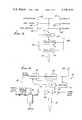
- FIG. 8is a predictive model circuit diagram implemented in the FIG. 7 remote computer
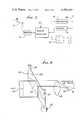
- FIG. 9is a perspective view of a signal generation means to develop signals as a function of consumptive use of water and desired moisture level.
- farms or fieldsare shown at 10, with a remote central computer at 11.
- Remote computers 12are associated with the farms.
- the central computer 11serves to provide backup data storage; and to provide updated information to the remote computers. Transmission between the remote computers and the central computer is via ordinary telephone lines, indicated at 13.
- Each remote computercan handle many separate fields at a farm.
- a typical farm 15includes several fields 15a.
- a remote computer 16which is able to communicate via radio or other means with various sensor and control units 17 and 18 located throughout the farm or fields.
- Each fieldis typically instrumented with several soil sensor stations or units; in FIG. 2, three such soil sensor stations are shown in one field and spaced along and between crop rows 200.
- many fieldscould be instrumented, and with as many sensor stations as are needed to characterize that field, i.e. to develop soil moisture data characteristic of the field.
- a weather station 19is provided and may be located in any field. This station supplies data including, but not limited to: temperature, humidity wind velocity, wind direction, insolation (sun intensity), and rainfall amount. Antennas associated with the described elements are indicated at 16a, 17a, 18a and 19a.
- the systemis able to control irrigation (start and stop pumps, open and close valves, etc.) for those farms where such facilities are available. See for example pump or valve 20 connected at 21 with controller 18.
- the pump or valvetypically controls water flow to one or more of the fields 15a.
- FIG. 3shows a typical portable soil sensor station 17. It comprises a self-contained unit which is placed in the field, and operates to telemeter data indicative of the moisture level in the soil in the vicinity of the active region of the crop roots at that portion of the field where the station is located.
- the stationis designed so that it can be easily installed in the field, and easily removed, so as to facilitate harvesting and field preparation.
- the support shaft or mast 26has a lower portion 26a incorporating or carrying the moisture sensitive elements 27a of the tensiometers 27.
- the tensiometer elementsare placed in proximity with the active areas of the plant roots 28 as by implanting the lower portion 26a underground, i.e. below ground level 29. Note tapered lower portion of that mast, easily forced into the earth. Markers 30 on the mast indicate depth of soil penetration.
- the units 17may be placed along rows of planted crops, and the construction described above allows the sensors to take up a minimum of space along the rows, with minimum interference with farm operations.
- the support shaft or mast 26also has an upper or above ground portion 26c which provides a mounting means for: a radio antenna 17a or other means of telemetry; a protective case 32 which contains electrical components, such as transmitters, receivers; etc; and a solar panel 33 to provide electrical power to the electrical devices at the station 17.
- Examples of usable tensiometersare those described in U.S. Pat. No. 3,224,676. Their vertical spacing enables ascertainment of soil moisture data at two depths, for establishing a moisture gradient.
- FIG. 4illustrates the electrical components of a typical sensor station 17.
- Power developed at the solar panel 33is delivered at 34 to a voltage regulator circuit 35 and used to charge a rechargable battery 36.
- the systemtypically provides power without wires, and allows power availability during times without sunlight. Power from the rechargable battery is supplied at 37 to all other stages of the unit.
- Commands from the remote computer 16are received via antenna 17a and receiver-amplifier 38, and then sent at 39 to a controller 40. The latter verifies that the commands were addressed to that particular sensor station; and determines the measurement desired.
- a controller 40verifies that the commands were addressed to that particular sensor station; and determines the measurement desired.
- the pressure in the tensiometersas sensed by pressure transducers 41, is used to modulate the transmitted waveform. For example, the voltage outputs of transducers 41 modulate (at modulator 42) the waveform transmitted via transmitter 43).
- the pressureis telemetered back to the remote computer 16 upon command.
- FIG. 5shows a representation of the circuitry in the weather station 19.
- Dataincluding, but not limited to, the following are collected by conventional instruments 44-49; temperature, windspeed, wind direction, humidity, insolation, and rainfall.
- These instruments, together with encoder 50, transmitter 51 and receiver 52 componentsare carried by a mast or shaft 53 (like shaft 26) and adapted to be removably implanted in the soil.
- the remote computer 16addresses the weather station through antenna 19a and the radio receiver 52, or other communication system as may be provided. Upon receipt of such a command, an enabling signal is transmitted at 54 to the encoder 50, enabling it to encode the collected weather data (fed to the encoder at 55), and transmit same to the remote computer (via transmitter 51 and antenna 19a).
- FIG. 6shows a typical pump control/monitor station 18. Its purpose is to allow the remote computer to command the pumps to start or stop; and to allow data concerning the pump's operation to be transmitted to the remote computer.
- Transmitted commands from the remote computer 16are received via antenna 18a and receiver 60, and processed by a controller 61.
- the controllercan either control the pump; or it can collect data about the pump's operation. If the command is to control the pump, then controller 61 enables at 62 a power controller 63, which turns the power to the pump 20 on or off as appropriate. A power meter appears at 64.
- the received commandis to collect data
- either the energy consumption or the water flowis encoded at 65 and telemetered at 66.
- Data from water meter 67is transmitted at 68 to the encoder, and data from the power meter 64 is transmitted at 69 to the encoder.
- the physical construction of the pump control/monitor stationis similar to the soil sensor station shown in FIG. 3 i.e. the components 18a, and 60-69 may be carried by a mast or shaft 70 removably implanted in the soil, adjacent pump 20.
- FIG. 7shows the remote computer 16, which collects data from the fields, makes decision about optimal irrigation strategy, communicates with the central computer, and communicates with the farmer.
- the internal characteristics of the remote computerare illustrated in the following figures.
- the remote computeris able to communicate with the central computer using a modem (modulator-demodulator) 71 of conventional design, such as a Bell type 103. In turn, communication is through the existing telephone network 13.
- a modemmodulator-demodulator
- Control/display function at 72is provided using potentiometers, switches, dials, which indicate the status of the internal circuits and allow control thereof.
- a radio transmitter/receiver or other means of communication with the sensors and controllers in the fieldis provided by antenna 16a, receiver 74 and transmitter 75.
- datais collected in the computer memory from the soil sensors which indicates the free moisture in various portions of each field.
- Weather datais collected from the weather station.
- Meansis provided to supply data to the computer indicative of the consumptive use characteristics of the crop (the variations in water consumption throughout the growing seasons). Characteristics such as soil type, irrigation flow rate, etc. are thereby applied.
- the farmercan provide additional information, such as "water now,” “do not water,” etc.
- the remote computerdevelops a predictive model of the amount of soil moisture in each field; and predicts the optimal irrigation strategy. In this regard it is distinctive, and is predictive, rather than reactive.
- FIG. 8shows one possible implementation using analog electronic circuits. Voltages corresponding to temperature, insolation (sun intensity) and humidity are derived from data collected by the weather station. These voltages supplied on lines 76-78 are summed at 79 with appropriate weighting. The humidity, in this case, would have a negative weight, represented by the invertor 80 in the figure. The exact weighting factors would vary from case to case, and can be varied as by controls 76a,77a and 78a. The weighted summing can be implemented in several ways, one of which would be conventional operational amplifiers.
- This weighted summingwould be a voltage (transmitted at 81) which is an analog of the overall weather situation; hotter, dryer weather would in general be represented by a greater voltage.
- This signalis also optionally displayed at 82 to the human operator. It is labelled "weather factor" in the figure.
- a voltage(supplied at 84) which is an analog of the soil characteristics. Since this factor would be constant over extended periods of time, it may be set by a potentiometer 85. In the particular model shown, a higher voltage would be analogous to sandy soil, in which water was rapidly lost through downward percolation. A lower voltage would represent clayey soil which tended to retain water.
- a third input at 86is a voltage analogous to the consumption use of the crop. This is labelled “consumptive use factor" in the figure. It corresponds to the rate at which water is consumed by the plants themselves. A greater voltage represents greater water consumption, such as during a very active growing phase. The consumptive use factor depends on the crop type, location, phase of the growing season, etc. FIG. 9 shows one means for developing this voltage analog.
- water use factoris an analog of the overall water lost from the soil for all reasons in the model.
- a voltageis stored on capacitor C.
- This voltage appearing at 92is labelled “modelled soil moisture,” and is an analog of the estimate of the amount of water stored in the soil.
- the water use factoris used to control a voltage controlled resistor 93. A greater water use factor would cause the resistance to decrease. Such a decrease would cause capacitor C to discharge at a greater rate.
- the discharge current at 94is labelled “water loss” in the figure.
- watercan be added to the soil from two sources: rainfall and irrigation.
- a voltage analogous of the rate of rainfallis developed at 95 from data collected from the weather stations. This is labelled “rainfall rate” in the figure. No rainfall is represented by zero volts, and greater rainfall is represented by greater voltages.
- a current proportional to the rate of rainfallflows at 96 through the variable resistor 97 labelled rainfall scale factor, and charges the capacitor C. This causes an increase in the modelled soil moisture.
- the impedance of the rainfall scale factor resistoris determined by the particular location, and factors such as the portion of rainfall which is absorbed by the soil, rather than drained away and lost, etc.
- a second method by which the modelled soil moisture can be increasedis if irrigation is performed.
- the modelissues an "irrigate" command (in a manner to be described below) then relay Y is energized.
- Currentflows from source 100 through the variable resistor 98 labelled “irrigation rate factor,” and charges capacitor C. This, in turn, increases the modelled soil moisture.
- the irrigation rate factor resistoris adjusted to represent the particular installation; for example, large pumps would be modelled by a small value of the resistor, and corresponding large currents.
- Voltages analogous to the measured soil moisture levelsare developed. These are based on the data obtained from the soil sensor stations described previously. They are labelled “soil moisture levels” 101 in the figure; higher voltages represent greater measured moistures. These voltages are applied to a circuit 102 which produces as its output 103 a voltage analogous to the overall moisture level in the field and which is a function of levels 101.
- the exact functional relationship between the several soil moisture levels, and the representative single value, labelled "present water factor" in the figurecould be any one of many. For example, one possibility would be for the present water factor to be the simple average of the several soil moisture levels. Another possibility might be to use the lowest of the soil moisture levels, thus basing actions on the dryest. Another might be to use the tenth percentile, or other means. In any case, a single voltage analogous of the overall actual condition of soil moisture is developed at 103.
- the modelled soil moisture signal 92is then compared with the actual overall soil moisture (signal 103) in a differencing circuit 104.
- the output 105 of this differencing circuitis a correction factor which represent error in the model when compared to actuality.
- This correction factoris passed through a low pass circuit 106 which eliminates short term difference, and develops a signal 107 labelled "long term averaged difference.”
- This voltageis analogous to the long term difference between the modelled soil moisture and the observed soil moisture.
- the long term averaged difference signal 107is summed in summing circuit 109 with the modelled soil moisture signal 42 to produce a signal 110 labelled "corrected modelled soil moisture" in the figure. This is the model's best estimate of the soil moisture.
- a voltage 111 labelled “desired soil moisture level” in the figureAnother input to the system is a voltage 111 labelled "desired soil moisture level" in the figure. This could be set by a potentiometer at 112 if it remains relatively constant, or could be generated by a device such as is shown in FIG. 9. This is analogous to the desired level of moisture in the soil; and depends on the crop type, location and other factors; and may in some cases vary through the growing season.
- the desired soil moisturecan also be set to a very high value or a very low value, using the switch labelled "override control" 113.
- the desired soil moistureis compared with the corrected modelled soil moisture, in the comparator 114. If the desired moisture is less than the corrected model, then the output 115 of the comparator goes high, and irrigation is commenced via pump controls 61 and 62.
- a display 116also indicates the beginning of irrigation, and relay Y is energized, so that the modelled soil moisture can be adjusted to reflect the beginning of irrigation.
- the output of the comparatorgoes low, a command to discontinue irrigation is issued, and relay Y is deenergized.
- the model shown in the figure and described hereis one means to provide a predictive model of soil moisture, and an optimal means of irrigation control.
- Certain signals used by the model described previouslymay vary throughout the growing season. These include the consumptive use of water by plants; and also the desired soil moisture levels. FIG. 9 shows one means to develop these signals.
- a narrow, parallel beam of light 120is generated.
- This beam of lightis directed through a strip of photographic film 121 of other material which has been prepared with a clear (transparent) region 122 and an opaque region 123.
- the strip of filmis slowly moved from a supply spool 124 to take-up spool 125 during the course of the growing season. At any time in the season, the portion of the film through which the light shines has a transparent area which is analogous to the value of the appropriate signal (consumptive use) at that time.
- the light which then passes through the stripis proportional to the portion of the strip which is transparent.
- the lightis concentrated by a lens 126 and is used to illuminate a photocell 127.
- the voltaged developed by the photocellis representative of the desired signal.
- a very slow speed drive for the take-up spoolis indicated at 128.
Landscapes
- Life Sciences & Earth Sciences (AREA)
- Engineering & Computer Science (AREA)
- Water Supply & Treatment (AREA)
- Environmental Sciences (AREA)
- Soil Sciences (AREA)
- Investigating Or Analyzing Materials By The Use Of Electric Means (AREA)
Abstract
Description
______________________________________ Components Model and Manufacturer ______________________________________ 11 Digital Equipment Corp. PDP-11/70Computer 16 Digital Equipment Corp. PDP-11/03Computer 20 Rainbird EP-300-F 27Irrometer 33 Photowatt International MA 2320 35Motorola MC7812 38 REPCO 810-055 40 National Semiconductor LX 1702AFN 41 National Semiconductor LX 1702AFN 42 Creative Micro Systems 9651-509 43 REPCO 810-038 44 Weather Measure T 621 45Weather Measure W 121 46Weather Measure W 121 47 Weather Measure H 352 48 Weather Measure R 413 49Weather Measure P532 50 Creative Micro Systems 9651-513 51 REPCO 810-038 52 REPCO 810-055 60 REPCO 810-055 61 Creative Micro Systems 9651-505 63 Westinghouse BF-02-F 64General Electric DSW 43 65 Creative Micro Systems 9651-513 66 REPCO 810-038 67Brooks Instruments 10 71 RACAL-VADIC VA 305 72Teletype 43 74 REPCO 810-055 75 REPCO 810-038 79 National Semiconductor LM 324 80 National Semiconductor LM 324 90 National Semiconductor LM 324 102 National Semiconductor LM 324 104 National Semiconductor LM 324 106 National Semiconductor AF-150 109 National Semiconductor LM 324 114 National Semiconductor LM 311 ______________________________________
Claims (23)
Priority Applications (2)
| Application Number | Priority Date | Filing Date | Title |
|---|---|---|---|
| US06/221,519US4396149A (en) | 1980-12-30 | 1980-12-30 | Irrigation control system |
| US06/512,667US4567563A (en) | 1980-12-30 | 1983-07-11 | Irrigation control system |
Applications Claiming Priority (1)
| Application Number | Priority Date | Filing Date | Title |
|---|---|---|---|
| US06/221,519US4396149A (en) | 1980-12-30 | 1980-12-30 | Irrigation control system |
Related Child Applications (1)
| Application Number | Title | Priority Date | Filing Date |
|---|---|---|---|
| US06/512,667Continuation-In-PartUS4567563A (en) | 1980-12-30 | 1983-07-11 | Irrigation control system |
Publications (1)
| Publication Number | Publication Date |
|---|---|
| US4396149Atrue US4396149A (en) | 1983-08-02 |
Family
ID=22828160
Family Applications (1)
| Application Number | Title | Priority Date | Filing Date |
|---|---|---|---|
| US06/221,519Expired - Fee RelatedUS4396149A (en) | 1980-12-30 | 1980-12-30 | Irrigation control system |
Country Status (1)
| Country | Link |
|---|---|
| US (1) | US4396149A (en) |
Cited By (124)
| Publication number | Priority date | Publication date | Assignee | Title |
|---|---|---|---|---|
| FR2561065A1 (en)* | 1984-03-16 | 1985-09-20 | Provence Amenag Region Prov Ca | Methods and system for running an irrigation installation |
| US4545396A (en)* | 1985-02-25 | 1985-10-08 | Miller Richard N | System for optimum irrigating and fertilizing |
| US4567563A (en)* | 1980-12-30 | 1986-01-28 | Energy Management Corporation | Irrigation control system |
| WO1986005353A1 (en)* | 1985-03-22 | 1986-09-25 | Dronningborg Maskinfabrik A/S | Agricultural husbandry |
| FR2586330A1 (en)* | 1985-08-16 | 1987-02-20 | Bassoullet Bernard | Method and implementation device for determining the hygrometry of the soil, in particular of cultivated spaces |
| US4646224A (en)* | 1983-12-05 | 1987-02-24 | L. R. Nelson Corporation | Sprinkler controller which computes sprinkler cycles based on inputted data |
| EP0202847A3 (en)* | 1985-05-17 | 1987-06-16 | The Standard Oil Company | System and method for scheduling irrigation |
| WO1987004275A1 (en)* | 1986-01-14 | 1987-07-16 | Auditel Systems Pty. Ltd. | Remote process control apparatus |
| US4744515A (en)* | 1983-11-02 | 1988-05-17 | Konan Seiko Co., Ltd. | Automatic water-sprinkling controller |
| US4837499A (en)* | 1986-05-19 | 1989-06-06 | Scherer Iii Robert P | Moisture sensing device |
| US4852802A (en)* | 1988-08-08 | 1989-08-01 | Jerry Iggulden | Smart irrigation sprinklers |
| WO1989012510A1 (en)* | 1988-06-22 | 1989-12-28 | The Minister For Agriculture And Rural Affairs Of | Controller for agricultural sprays |
| US4952868A (en)* | 1986-05-19 | 1990-08-28 | Scherer Iii Robert P | Moisture sensing system for an irrigation system |
| US4962522A (en)* | 1987-12-04 | 1990-10-09 | Marian Michael B | Electronic controller for sprinkler systems |
| US4987913A (en)* | 1988-06-25 | 1991-01-29 | Kabushiki Kaisha Toshiba | Apparatus and method for controlling operation of storm sewage pump |
| US4993640A (en)* | 1989-06-12 | 1991-02-19 | Baugh Mark R | Fluid control system |
| FR2680629A1 (en)* | 1991-08-28 | 1993-03-05 | Travaux Automatisme Et | Device for controlling a network of irrigation means installed in a specific zone |
| US5207380A (en)* | 1992-02-26 | 1993-05-04 | Frank Harryman | Irrigation control system |
| US5333785A (en)* | 1991-12-19 | 1994-08-02 | Dodds Graeme C | Wireless irrigation system |
| US5337957A (en)* | 1993-07-01 | 1994-08-16 | Olson Troy C | Microprocessor-based irrigation system with moisture sensors in multiple zones |
| US5414618A (en)* | 1990-07-18 | 1995-05-09 | The Toro Company | Irrigation controller with analog data input devices |
| US5465904A (en)* | 1993-12-03 | 1995-11-14 | Vaello; Donald B. | Domestic watering and agricultural irrigation control system |
| US5601236A (en)* | 1995-01-18 | 1997-02-11 | Wold; Keith F. | Plant watering device and method for promoting plant growth |
| US5628364A (en)* | 1995-12-04 | 1997-05-13 | Terrane Remediation, Inc. | Control system for governing in-situ removal of subterranean hydrocarbon-based fluids |
| ES2102308A1 (en)* | 1994-06-07 | 1997-07-16 | Proenza Eduardo Oliva | High-speed system control |
| US5678771A (en)* | 1996-04-19 | 1997-10-21 | Valmont Industries, Inc. | Chemical distribution system |
| US5696671A (en)* | 1994-02-17 | 1997-12-09 | Waterlink Systems, Inc. | Evapotranspiration forecasting irrigation control system |
| US5740031A (en)* | 1995-09-07 | 1998-04-14 | Smart Rain Corp. Inc. | Control system for the irrigation of watering stations |
| WO1998018025A1 (en)* | 1996-10-24 | 1998-04-30 | Echotec, Inc. | Earthquake forecast method and apparatus |
| ES2115549A1 (en)* | 1996-10-08 | 1998-06-16 | Sidsa Semiconductores Investig | Automated quick-method system for the control of nutrients for cultivatable plants |
| ES2115556A1 (en)* | 1996-11-28 | 1998-06-16 | Correas Juan Pablo Domingo | Irrigation control system |
| GB2320572A (en)* | 1996-12-19 | 1998-06-24 | Peter Hulme | Plant moisture detector |
| US5783945A (en)* | 1996-10-24 | 1998-07-21 | Balbachan; Michail | Earthquake forecast method and apparatus with measurement of electrical, temperature and humidity parameters of soil |
| WO1998038491A1 (en)* | 1997-02-28 | 1998-09-03 | Commonwealth Scientific And Industrial Research Organisation | Moisture detection |
| US5813606A (en)* | 1997-04-04 | 1998-09-29 | Ziff; Raymond | Radio controlled sprinkler control system |
| US5825295A (en)* | 1997-04-08 | 1998-10-20 | The Curators Of The University Of Missouri | Irrigation signaling device |
| US5859536A (en)* | 1997-01-08 | 1999-01-12 | Oliver Haugen | Moisture sensor having low sensitivity to conductance changes |
| US5870302A (en)* | 1994-02-17 | 1999-02-09 | Waterlink Systems, Inc. | Evapotranspiration remote irrigation control system |
| US5878447A (en)* | 1997-10-24 | 1999-03-09 | Wkr Productions, Inc. | Automatic water regulator apparatus for filling a swimming pool or comparable body of water when the water level is low |
| US5927603A (en)* | 1997-09-30 | 1999-07-27 | J. R. Simplot Company | Closed loop control system, sensing apparatus and fluid application system for a precision irrigation device |
| US5960813A (en)* | 1997-07-25 | 1999-10-05 | Sturman; Oded E. | Solar powered programmable valve and methods of operation thereof |
| US6016971A (en)* | 1996-02-16 | 2000-01-25 | Albert B. Welch | Lawn watering system |
| US6076740A (en)* | 1996-02-02 | 2000-06-20 | Irrigation Control Networks Pty. Ltd. | Irrigation control system |
| US6098898A (en)* | 1999-04-02 | 2000-08-08 | Storch; Paul | Master control system for conserving water by sprinkler systems within a geographical region |
| US6102061A (en)* | 1998-05-20 | 2000-08-15 | Addink; John W. | Irrigation controller |
| US6234403B1 (en)* | 1999-01-04 | 2001-05-22 | Frank S. Grott | Sprinkler water conservation device |
| US6257264B1 (en) | 1999-01-25 | 2001-07-10 | Sturman Bg, Llc | Programmable electronic valve control system and methods of operation thereof |
| US6337971B1 (en) | 1997-10-14 | 2002-01-08 | Gerald L. Abts | System for controlling and monitoring agricultural field equipment and method |
| US6374101B1 (en) | 1997-01-24 | 2002-04-16 | Keyspan Technologies, Inc. | Pager-based controller |
| US6402049B1 (en)* | 2000-07-21 | 2002-06-11 | Jack V. Youngs, Jr. | Sprinkler timer system |
| WO2002046852A1 (en)* | 2000-12-07 | 2002-06-13 | Aqua Conservation Systems, Inc. | Recording and processing utility commodity usage |
| US6452499B1 (en) | 1998-10-07 | 2002-09-17 | Thomas Henry Runge | Wireless environmental sensor system |
| ES2176112A1 (en)* | 2001-02-05 | 2002-11-16 | Univ Granada | AUTOMATIC AND LOW COST SYSTEM FOR MANAGEMENT AND REMOTE CONTROL OF EXTENSIVE IRRIGATION NETWORKS. |
| US6592049B1 (en)* | 2002-06-28 | 2003-07-15 | Matthew Van Wolput | Water misting device |
| US20030182022A1 (en)* | 2002-03-21 | 2003-09-25 | John Addink | Interactive irrigation system |
| US20030179102A1 (en)* | 2001-12-26 | 2003-09-25 | Andrew Barnes | System for controlling irrigation applications |
| US20040015270A1 (en)* | 2002-03-21 | 2004-01-22 | Addink John W. | Interactive irrigation system |
| ES2204256A1 (en)* | 2001-11-23 | 2004-04-16 | Tanit Iberia, S.L. | Probe for measuring moisture content in soil, has multiple sensors, which are arranged at different distances from each other, and head is provided with electronic plate that contains circuit |
| ES2205994A1 (en)* | 2001-11-23 | 2004-05-01 | Tanit Iberia, S.L. | Plant irrigation control system for use in plant cultivation, has sensors which detect flow and pressure of fluid circulating in hydraulic valves and transmit detection signal to indicate that valves are working properly |
| US20040140902A1 (en)* | 2003-01-19 | 2004-07-22 | Staples Peter Ethan | Wireless soil moisture meter network |
| US20040195372A1 (en)* | 2002-12-25 | 2004-10-07 | Inc. Admn. Agncy, Nat. Agr. & Bio-Orntd Rsrch Org | Intermittent automatic irrigation system |
| US20040217189A1 (en)* | 2003-04-09 | 2004-11-04 | Irvine Ranch Water District | System and method for controlling irrigation |
| US6829476B1 (en) | 1997-01-24 | 2004-12-07 | Lawrence J. Gelbein | Pager-based gas valve controller |
| US20050156068A1 (en)* | 2004-01-20 | 2005-07-21 | Norman Ivans | System and method for communicating data in an automated irrigation system |
| US6950728B1 (en) | 2000-08-17 | 2005-09-27 | Aqua Conservation Systems, Inc. | Interactive irrigation system |
| US6975245B1 (en)* | 2000-09-18 | 2005-12-13 | Battelle Energy Alliance, Llc | Real-time data acquisition and telemetry based irrigation control system |
| WO2005118153A1 (en)* | 2004-05-28 | 2005-12-15 | Jardinier Planter Systems, Inc. | Water-conserving surface irrigation systems and methods |
| US20060030971A1 (en)* | 2004-08-06 | 2006-02-09 | Arnold Nelson | Modular irrigation controller |
| US20060027676A1 (en)* | 2004-08-03 | 2006-02-09 | Intelligent Lawn Systems, L.P. | Methods, systems and apparatuses for automated irrigation and chemical treatment |
| US20060037380A1 (en)* | 2003-01-17 | 2006-02-23 | Enocean Gmbh | Sensor |
| US20060043208A1 (en)* | 2004-08-21 | 2006-03-02 | Graham Glen G | Systems and methods for adaptation to wireless remote control of irrigation valves from existing hardwired control devices |
| US7010394B1 (en) | 2002-10-24 | 2006-03-07 | The Toro Company | Intelligent environmental sensor for irrigation systems |
| US20060054214A1 (en)* | 2004-06-30 | 2006-03-16 | Caamano Ramon A | Low power system for wireless monitoring of an environment and irrigation control |
| US20060091245A1 (en)* | 2004-10-30 | 2006-05-04 | Norman Ivans | Irrigation unit having a control system and a data storage unit |
| US20060102739A1 (en)* | 2004-10-30 | 2006-05-18 | Norman Ivans | System and method for systematically irrigating subregions of an irrigation region |
| US20060102734A1 (en)* | 2004-10-30 | 2006-05-18 | Norman Ivans | System and method for maintaining irrigation accuracy of an irrigation system |
| US20060122736A1 (en)* | 2003-04-25 | 2006-06-08 | George Alexanian | Irrigation controller water management with temperature budgeting |
| US20060131441A1 (en)* | 2004-12-22 | 2006-06-22 | Norman Ivans | Irrigation unit having a control system that performs a self-test and a cleaner that cleans the unit |
| US20060131442A1 (en)* | 2004-12-22 | 2006-06-22 | Norman Ivans | Irrigation unit including a nozzle greater accuracy and improved adjustment properties |
| US20060161309A1 (en)* | 2002-04-19 | 2006-07-20 | Moore Steven E | Irrigation control system |
| US20060178847A1 (en)* | 2005-02-09 | 2006-08-10 | Glancy John E | Apparatus and method for wireless real time measurement and control of soil and turf conditions |
| US20070106426A1 (en)* | 2005-07-19 | 2007-05-10 | Rain Bird Corporation | Wireless Extension to an Irrigation Control System and Related Methods |
| US20070173981A1 (en)* | 2006-01-20 | 2007-07-26 | Vidovich Nikola V | Method and apparatus using soil conductivity thresholds to control irrigating plants |
| US20070293990A1 (en)* | 2003-04-25 | 2007-12-20 | George Alexanain | Irrigation water conservation with temperature budgeting and time of use technology |
| US20080027586A1 (en)* | 2006-06-20 | 2008-01-31 | Rain Bird Corporation | Sensor Device For Interrupting Irrigation |
| US20080034859A1 (en)* | 2006-08-08 | 2008-02-14 | The Toro Company | Raindrop Sensor For An Irrigation System |
| US7383721B2 (en) | 2002-06-24 | 2008-06-10 | Arichell Technologies Inc. | Leak Detector |
| US20080154437A1 (en)* | 2003-04-25 | 2008-06-26 | George Alexanian | Landscape irrigation time of use scheduling |
| US7403840B2 (en) | 2002-04-19 | 2008-07-22 | Irrisoft, Inc. | Irrigation control system |
| US20080223951A1 (en)* | 2007-02-23 | 2008-09-18 | Great Stuff, Inc. | Remote control for valve and hose reel system |
| WO2009073647A1 (en)* | 2007-12-07 | 2009-06-11 | Deere & Company | System and method of managing substances in a plant root zone |
| US20090303071A1 (en)* | 2008-06-05 | 2009-12-10 | Noel Wayne Anderson | Non-toxic, biodegradable sensor nodes for use with a wireless network |
| US20090301573A1 (en)* | 2003-03-13 | 2009-12-10 | Great Stuff Inc. | Remote control for hose operation |
| US20100032493A1 (en)* | 2008-08-06 | 2010-02-11 | Kevin Abts | Precision variable rate irrigation system |
| US7810515B2 (en) | 2007-03-14 | 2010-10-12 | Melnor, Inc. | Smart water timer |
| US20110093123A1 (en)* | 2003-04-25 | 2011-04-21 | George Alexanian | Irrigation water conservation with automated water budgeting and time of use technology |
| US20120188057A1 (en)* | 2011-01-24 | 2012-07-26 | Ole Green | Controller for a wireless sensor |
| US8302881B1 (en)* | 2009-02-02 | 2012-11-06 | Green Badge, LLC | Method and system for soil and water resources |
| USRE43903E1 (en) | 1997-02-13 | 2013-01-01 | Richmond Ip Holdings, Llc | Severe weather detector and alarm |
| US8368529B1 (en) | 2009-02-03 | 2013-02-05 | Green Badge, LLC | Antenna circuit matching the soil conditions |
| US8538592B2 (en) | 2003-04-25 | 2013-09-17 | George Alexanian | Landscape irrigation management with automated water budget and seasonal adjust, and automated implementation of watering restrictions |
| US8682494B1 (en) | 2009-02-02 | 2014-03-25 | Green Badge, LLC | Methods for performing soil measurements including defining antenna configuration based on sensor burial depth |
| US8744772B1 (en) | 2009-10-26 | 2014-06-03 | Green Badge, LLC | Method for soil analysis |
| US8751052B1 (en) | 2010-02-01 | 2014-06-10 | Green Badge, LLC | Automatic efficient irrigation threshold setting |
| US20140230917A1 (en)* | 2013-02-19 | 2014-08-21 | Trimble Navigation Limited | Moisture sensing watering system |
| US8862277B1 (en) | 2010-02-01 | 2014-10-14 | Green Badge, LLC | Automatic efficient irrigation threshold setting |
| US8885558B2 (en) | 2011-09-28 | 2014-11-11 | Robert Bosch Gmbh | System and method for multiple access sensor networks |
| US8981946B2 (en) | 2011-10-24 | 2015-03-17 | The Toro Company | Soil moisture sensor |
| US9007050B2 (en) | 2010-09-17 | 2015-04-14 | The Toro Company | Soil moisture sensor with improved enclosure |
| US9046461B1 (en) | 2009-02-03 | 2015-06-02 | Green Badge, LLC | RF amplifier tuning method for coping with expected variations in local dielectric |
| US9144204B2 (en) | 2006-06-20 | 2015-09-29 | Rain Bird Corporation | User interface for a sensor-based interface device for interrupting an irrigation controller |
| US9202252B1 (en) | 2010-03-31 | 2015-12-01 | SWIIM System, Ltd. | System and method for conserving water and optimizing land and water use |
| US9244449B2 (en) | 2011-11-29 | 2016-01-26 | Rain Bird Corporation | Wireless irrigation control |
| WO2016059628A1 (en)* | 2014-10-12 | 2016-04-21 | Korol Oleg | System and method for determining watering needs for field or landscape irrigation |
| US9538713B2 (en) | 2012-07-13 | 2017-01-10 | The Toro Company | Modular irrigation controller |
| JP2017192368A (en)* | 2016-04-22 | 2017-10-26 | 株式会社クボタケミックス | Solar cell unit for field electrical apparatus and field electric actuator |
| US20190037787A1 (en)* | 2017-08-03 | 2019-02-07 | Lalit Kumar | Smart Moisture Meter |
| US10444769B2 (en) | 2017-04-24 | 2019-10-15 | Rain Bird Corporation | Sensor-based interruption of an irrigation controller |
| US20190320601A1 (en)* | 2018-04-18 | 2019-10-24 | Agrome Inc. | Robotic agricultural irrigation and analysis system |
| US10757873B2 (en) | 2017-04-24 | 2020-09-01 | Rain Bird Corporation | Sensor-based interruption of an irrigation controller |
| US10968589B2 (en)* | 2014-01-13 | 2021-04-06 | Charlie J. Schafer | Water monitoring and control system and method thereof |
| US11006589B2 (en) | 2017-12-29 | 2021-05-18 | Rain Bird Corporation | Weather override irrigation control systems and methods |
| US20230337606A1 (en)* | 2022-04-20 | 2023-10-26 | Design Simplicity LLC | Intelligent irrigation system |
| US20250089636A1 (en)* | 2023-09-14 | 2025-03-20 | Auguste Roberts | Subterranean irrigation system |
Citations (27)
| Publication number | Priority date | Publication date | Assignee | Title |
|---|---|---|---|---|
| US3024372A (en)* | 1956-08-27 | 1962-03-06 | Harold A Seele | Automatic control means for sprinklers |
| US3079089A (en)* | 1961-06-02 | 1963-02-26 | Robert L Tomayer | Electronic moisture sensing control system |
| US3113724A (en)* | 1962-04-16 | 1963-12-10 | Bough Bjorn N De | Automatic watering systems |
| US3114243A (en)* | 1959-07-02 | 1963-12-17 | Willis R Winters | Automatic system of agricultural irrigation |
| US3195816A (en)* | 1962-03-13 | 1965-07-20 | Richard H Mercer | Low-voltage sprinkler control system |
| US3238392A (en)* | 1963-02-21 | 1966-03-01 | John A Richards | Moisture-governed automatic control for irrigation system |
| US3297254A (en)* | 1964-08-06 | 1967-01-10 | Alfred C Coffman | Rain-controlled lawn sprinkler |
| US3438575A (en)* | 1967-05-24 | 1969-04-15 | Hermann Rohling | Root controlled watering device |
| US3463396A (en)* | 1966-08-26 | 1969-08-26 | Plessey Fabrieken Nv | Temperature-controlled sprayer apparatus |
| GB1165652A (en)* | 1967-03-20 | 1969-10-01 | Chevreliere Charles A De La | Improvements in and relating to Automatic Soil-Sprinkling Arrangements. |
| US3488000A (en)* | 1968-11-04 | 1970-01-06 | Frank D Cramer | Automatic water sprinkling system |
| US3500844A (en)* | 1965-05-18 | 1970-03-17 | George E Sanner | Controls for lawn sprinkling systems and the like |
| US3553481A (en)* | 1968-07-24 | 1971-01-05 | Harold W Hasenbeck | Automatic soil watering system |
| US3603951A (en)* | 1968-09-03 | 1971-09-07 | Montech Inc | Storm warning system |
| US3626286A (en)* | 1968-11-20 | 1971-12-07 | George P Rauchwerger | Capacitive moisture control system having a peak detector |
| US3642204A (en)* | 1969-11-28 | 1972-02-15 | Edward W Mccloskey | Waterflow-controlling apparatus for an automatic irrigation system |
| US3747399A (en)* | 1971-08-17 | 1973-07-24 | E Treirat | Moisture responsive device |
| US3847351A (en)* | 1973-06-29 | 1974-11-12 | H Hasenbeck | Soil matric potential sensor |
| US3874590A (en)* | 1973-10-19 | 1975-04-01 | William H Gibson | Moisture responsive apparatus for controlling moisture content of soil |
| US3906978A (en)* | 1972-08-22 | 1975-09-23 | Reinhard Kurz | Control unit for automatic watering of flowers |
| US3910300A (en)* | 1972-09-29 | 1975-10-07 | Aharon Tal | Tensiometer and automatic irrigation control system utilizing same |
| US3991939A (en)* | 1975-07-16 | 1976-11-16 | William Richard Maclay | System for spraying and cooling vegetation |
| US4026467A (en)* | 1975-04-11 | 1977-05-31 | Ayme De La Chevreliere Charles | Irrigation control apparatus |
| US4114647A (en)* | 1976-03-01 | 1978-09-19 | Clifton J. Burwell | Fluid control system and controller and moisture sensor therefor |
| US4197866A (en)* | 1977-09-19 | 1980-04-15 | Neal Jerry D | Soil moisture sampler and controller |
| US4209131A (en)* | 1978-05-12 | 1980-06-24 | Motorola, Inc. | Computer-controlled irrigation system |
| US4256133A (en)* | 1977-08-22 | 1981-03-17 | Coward Noel D | Watering valve device |
- 1980
- 1980-12-30USUS06/221,519patent/US4396149A/ennot_activeExpired - Fee Related
Patent Citations (28)
| Publication number | Priority date | Publication date | Assignee | Title |
|---|---|---|---|---|
| US3024372A (en)* | 1956-08-27 | 1962-03-06 | Harold A Seele | Automatic control means for sprinklers |
| US3114243A (en)* | 1959-07-02 | 1963-12-17 | Willis R Winters | Automatic system of agricultural irrigation |
| US3079089A (en)* | 1961-06-02 | 1963-02-26 | Robert L Tomayer | Electronic moisture sensing control system |
| US3195816A (en)* | 1962-03-13 | 1965-07-20 | Richard H Mercer | Low-voltage sprinkler control system |
| US3113724A (en)* | 1962-04-16 | 1963-12-10 | Bough Bjorn N De | Automatic watering systems |
| US3238392A (en)* | 1963-02-21 | 1966-03-01 | John A Richards | Moisture-governed automatic control for irrigation system |
| US3297254A (en)* | 1964-08-06 | 1967-01-10 | Alfred C Coffman | Rain-controlled lawn sprinkler |
| US3500844A (en)* | 1965-05-18 | 1970-03-17 | George E Sanner | Controls for lawn sprinkling systems and the like |
| US3463396A (en)* | 1966-08-26 | 1969-08-26 | Plessey Fabrieken Nv | Temperature-controlled sprayer apparatus |
| GB1165652A (en)* | 1967-03-20 | 1969-10-01 | Chevreliere Charles A De La | Improvements in and relating to Automatic Soil-Sprinkling Arrangements. |
| US3905551A (en)* | 1967-03-20 | 1975-09-16 | De La Chevreliere Charles Ayme | Automatic soil-sprinkling arrangements |
| US3438575A (en)* | 1967-05-24 | 1969-04-15 | Hermann Rohling | Root controlled watering device |
| US3553481A (en)* | 1968-07-24 | 1971-01-05 | Harold W Hasenbeck | Automatic soil watering system |
| US3603951A (en)* | 1968-09-03 | 1971-09-07 | Montech Inc | Storm warning system |
| US3488000A (en)* | 1968-11-04 | 1970-01-06 | Frank D Cramer | Automatic water sprinkling system |
| US3626286A (en)* | 1968-11-20 | 1971-12-07 | George P Rauchwerger | Capacitive moisture control system having a peak detector |
| US3642204A (en)* | 1969-11-28 | 1972-02-15 | Edward W Mccloskey | Waterflow-controlling apparatus for an automatic irrigation system |
| US3747399A (en)* | 1971-08-17 | 1973-07-24 | E Treirat | Moisture responsive device |
| US3906978A (en)* | 1972-08-22 | 1975-09-23 | Reinhard Kurz | Control unit for automatic watering of flowers |
| US3910300A (en)* | 1972-09-29 | 1975-10-07 | Aharon Tal | Tensiometer and automatic irrigation control system utilizing same |
| US3847351A (en)* | 1973-06-29 | 1974-11-12 | H Hasenbeck | Soil matric potential sensor |
| US3874590A (en)* | 1973-10-19 | 1975-04-01 | William H Gibson | Moisture responsive apparatus for controlling moisture content of soil |
| US4026467A (en)* | 1975-04-11 | 1977-05-31 | Ayme De La Chevreliere Charles | Irrigation control apparatus |
| US3991939A (en)* | 1975-07-16 | 1976-11-16 | William Richard Maclay | System for spraying and cooling vegetation |
| US4114647A (en)* | 1976-03-01 | 1978-09-19 | Clifton J. Burwell | Fluid control system and controller and moisture sensor therefor |
| US4256133A (en)* | 1977-08-22 | 1981-03-17 | Coward Noel D | Watering valve device |
| US4197866A (en)* | 1977-09-19 | 1980-04-15 | Neal Jerry D | Soil moisture sampler and controller |
| US4209131A (en)* | 1978-05-12 | 1980-06-24 | Motorola, Inc. | Computer-controlled irrigation system |
Cited By (227)
| Publication number | Priority date | Publication date | Assignee | Title |
|---|---|---|---|---|
| US4567563A (en)* | 1980-12-30 | 1986-01-28 | Energy Management Corporation | Irrigation control system |
| US4744515A (en)* | 1983-11-02 | 1988-05-17 | Konan Seiko Co., Ltd. | Automatic water-sprinkling controller |
| US4646224A (en)* | 1983-12-05 | 1987-02-24 | L. R. Nelson Corporation | Sprinkler controller which computes sprinkler cycles based on inputted data |
| FR2561065A1 (en)* | 1984-03-16 | 1985-09-20 | Provence Amenag Region Prov Ca | Methods and system for running an irrigation installation |
| US4545396A (en)* | 1985-02-25 | 1985-10-08 | Miller Richard N | System for optimum irrigating and fertilizing |
| WO1986005353A1 (en)* | 1985-03-22 | 1986-09-25 | Dronningborg Maskinfabrik A/S | Agricultural husbandry |
| EP0202847A3 (en)* | 1985-05-17 | 1987-06-16 | The Standard Oil Company | System and method for scheduling irrigation |
| US4755942A (en)* | 1985-05-17 | 1988-07-05 | The Standard Oil Company | System for indicating water stress in crops which inhibits data collection if solar insolation exceeds a range from an initial measured value |
| FR2586330A1 (en)* | 1985-08-16 | 1987-02-20 | Bassoullet Bernard | Method and implementation device for determining the hygrometry of the soil, in particular of cultivated spaces |
| WO1987004275A1 (en)* | 1986-01-14 | 1987-07-16 | Auditel Systems Pty. Ltd. | Remote process control apparatus |
| US4952868A (en)* | 1986-05-19 | 1990-08-28 | Scherer Iii Robert P | Moisture sensing system for an irrigation system |
| US4837499A (en)* | 1986-05-19 | 1989-06-06 | Scherer Iii Robert P | Moisture sensing device |
| US4962522A (en)* | 1987-12-04 | 1990-10-09 | Marian Michael B | Electronic controller for sprinkler systems |
| WO1989012510A1 (en)* | 1988-06-22 | 1989-12-28 | The Minister For Agriculture And Rural Affairs Of | Controller for agricultural sprays |
| US4987913A (en)* | 1988-06-25 | 1991-01-29 | Kabushiki Kaisha Toshiba | Apparatus and method for controlling operation of storm sewage pump |
| US4852802A (en)* | 1988-08-08 | 1989-08-01 | Jerry Iggulden | Smart irrigation sprinklers |
| US4993640A (en)* | 1989-06-12 | 1991-02-19 | Baugh Mark R | Fluid control system |
| US5414618A (en)* | 1990-07-18 | 1995-05-09 | The Toro Company | Irrigation controller with analog data input devices |
| FR2680629A1 (en)* | 1991-08-28 | 1993-03-05 | Travaux Automatisme Et | Device for controlling a network of irrigation means installed in a specific zone |
| US5333785A (en)* | 1991-12-19 | 1994-08-02 | Dodds Graeme C | Wireless irrigation system |
| US5207380A (en)* | 1992-02-26 | 1993-05-04 | Frank Harryman | Irrigation control system |
| US5337957A (en)* | 1993-07-01 | 1994-08-16 | Olson Troy C | Microprocessor-based irrigation system with moisture sensors in multiple zones |
| US5465904A (en)* | 1993-12-03 | 1995-11-14 | Vaello; Donald B. | Domestic watering and agricultural irrigation control system |
| US5870302A (en)* | 1994-02-17 | 1999-02-09 | Waterlink Systems, Inc. | Evapotranspiration remote irrigation control system |
| US5696671A (en)* | 1994-02-17 | 1997-12-09 | Waterlink Systems, Inc. | Evapotranspiration forecasting irrigation control system |
| ES2102308A1 (en)* | 1994-06-07 | 1997-07-16 | Proenza Eduardo Oliva | High-speed system control |
| US5601236A (en)* | 1995-01-18 | 1997-02-11 | Wold; Keith F. | Plant watering device and method for promoting plant growth |
| US5740031A (en)* | 1995-09-07 | 1998-04-14 | Smart Rain Corp. Inc. | Control system for the irrigation of watering stations |
| US5628364A (en)* | 1995-12-04 | 1997-05-13 | Terrane Remediation, Inc. | Control system for governing in-situ removal of subterranean hydrocarbon-based fluids |
| US6076740A (en)* | 1996-02-02 | 2000-06-20 | Irrigation Control Networks Pty. Ltd. | Irrigation control system |
| US6016971A (en)* | 1996-02-16 | 2000-01-25 | Albert B. Welch | Lawn watering system |
| US5678771A (en)* | 1996-04-19 | 1997-10-21 | Valmont Industries, Inc. | Chemical distribution system |
| ES2115549A1 (en)* | 1996-10-08 | 1998-06-16 | Sidsa Semiconductores Investig | Automated quick-method system for the control of nutrients for cultivatable plants |
| US5783945A (en)* | 1996-10-24 | 1998-07-21 | Balbachan; Michail | Earthquake forecast method and apparatus with measurement of electrical, temperature and humidity parameters of soil |
| WO1998018025A1 (en)* | 1996-10-24 | 1998-04-30 | Echotec, Inc. | Earthquake forecast method and apparatus |
| ES2115556A1 (en)* | 1996-11-28 | 1998-06-16 | Correas Juan Pablo Domingo | Irrigation control system |
| GB2320572A (en)* | 1996-12-19 | 1998-06-24 | Peter Hulme | Plant moisture detector |
| US5859536A (en)* | 1997-01-08 | 1999-01-12 | Oliver Haugen | Moisture sensor having low sensitivity to conductance changes |
| US6829476B1 (en) | 1997-01-24 | 2004-12-07 | Lawrence J. Gelbein | Pager-based gas valve controller |
| US6374101B1 (en) | 1997-01-24 | 2002-04-16 | Keyspan Technologies, Inc. | Pager-based controller |
| USRE43903E1 (en) | 1997-02-13 | 2013-01-01 | Richmond Ip Holdings, Llc | Severe weather detector and alarm |
| USRE45514E1 (en) | 1997-02-13 | 2015-05-12 | La Crosse Technology Ip Holdings, Llc | Severe weather detector and alarm |
| WO1998038491A1 (en)* | 1997-02-28 | 1998-09-03 | Commonwealth Scientific And Industrial Research Organisation | Moisture detection |
| EP0975951A4 (en)* | 1997-02-28 | 2001-06-13 | Commw Scient Ind Res Org | Moisture detection |
| US6532803B2 (en) | 1997-02-28 | 2003-03-18 | Commonwealth Scientific And Industrial Research Organisation | Soil moisture detection |
| US5813606A (en)* | 1997-04-04 | 1998-09-29 | Ziff; Raymond | Radio controlled sprinkler control system |
| US5825295A (en)* | 1997-04-08 | 1998-10-20 | The Curators Of The University Of Missouri | Irrigation signaling device |
| US5960813A (en)* | 1997-07-25 | 1999-10-05 | Sturman; Oded E. | Solar powered programmable valve and methods of operation thereof |
| US5927603A (en)* | 1997-09-30 | 1999-07-27 | J. R. Simplot Company | Closed loop control system, sensing apparatus and fluid application system for a precision irrigation device |
| US6337971B1 (en) | 1997-10-14 | 2002-01-08 | Gerald L. Abts | System for controlling and monitoring agricultural field equipment and method |
| US5878447A (en)* | 1997-10-24 | 1999-03-09 | Wkr Productions, Inc. | Automatic water regulator apparatus for filling a swimming pool or comparable body of water when the water level is low |
| US6102061A (en)* | 1998-05-20 | 2000-08-15 | Addink; John W. | Irrigation controller |
| US6452499B1 (en) | 1998-10-07 | 2002-09-17 | Thomas Henry Runge | Wireless environmental sensor system |
| US6234403B1 (en)* | 1999-01-04 | 2001-05-22 | Frank S. Grott | Sprinkler water conservation device |
| US6257264B1 (en) | 1999-01-25 | 2001-07-10 | Sturman Bg, Llc | Programmable electronic valve control system and methods of operation thereof |
| US6098898A (en)* | 1999-04-02 | 2000-08-08 | Storch; Paul | Master control system for conserving water by sprinkler systems within a geographical region |
| US6402049B1 (en)* | 2000-07-21 | 2002-06-11 | Jack V. Youngs, Jr. | Sprinkler timer system |
| US6950728B1 (en) | 2000-08-17 | 2005-09-27 | Aqua Conservation Systems, Inc. | Interactive irrigation system |
| US6975245B1 (en)* | 2000-09-18 | 2005-12-13 | Battelle Energy Alliance, Llc | Real-time data acquisition and telemetry based irrigation control system |
| WO2002046852A1 (en)* | 2000-12-07 | 2002-06-13 | Aqua Conservation Systems, Inc. | Recording and processing utility commodity usage |
| ES2176112A1 (en)* | 2001-02-05 | 2002-11-16 | Univ Granada | AUTOMATIC AND LOW COST SYSTEM FOR MANAGEMENT AND REMOTE CONTROL OF EXTENSIVE IRRIGATION NETWORKS. |
| ES2204256B1 (en)* | 2001-11-23 | 2005-07-16 | Tanit Iberia, S.L. | PROBE FOR MEASURING SOIL MOISTURE. |
| ES2205994A1 (en)* | 2001-11-23 | 2004-05-01 | Tanit Iberia, S.L. | Plant irrigation control system for use in plant cultivation, has sensors which detect flow and pressure of fluid circulating in hydraulic valves and transmit detection signal to indicate that valves are working properly |
| ES2204256A1 (en)* | 2001-11-23 | 2004-04-16 | Tanit Iberia, S.L. | Probe for measuring moisture content in soil, has multiple sensors, which are arranged at different distances from each other, and head is provided with electronic plate that contains circuit |
| ES2205994B1 (en)* | 2001-11-23 | 2005-07-16 | Tanit Iberia, S.L. | IRRIGATION CONTROL SYSTEM IN PLANTS. |
| US20030179102A1 (en)* | 2001-12-26 | 2003-09-25 | Andrew Barnes | System for controlling irrigation applications |
| US20040015270A1 (en)* | 2002-03-21 | 2004-01-22 | Addink John W. | Interactive irrigation system |
| US20030182022A1 (en)* | 2002-03-21 | 2003-09-25 | John Addink | Interactive irrigation system |
| US7403840B2 (en) | 2002-04-19 | 2008-07-22 | Irrisoft, Inc. | Irrigation control system |
| US20060161309A1 (en)* | 2002-04-19 | 2006-07-20 | Moore Steven E | Irrigation control system |
| US20090326723A1 (en)* | 2002-04-19 | 2009-12-31 | Irrisoft, Inc. | Irrigation control system |
| US7383721B2 (en) | 2002-06-24 | 2008-06-10 | Arichell Technologies Inc. | Leak Detector |
| US9763393B2 (en) | 2002-06-24 | 2017-09-19 | Sloan Valve Company | Automated water delivery systems with feedback control |
| US6592049B1 (en)* | 2002-06-28 | 2003-07-15 | Matthew Van Wolput | Water misting device |
| US8862275B2 (en) | 2002-10-24 | 2014-10-14 | The Toro Company | Intelligent environmental sensor for irrigation systems |
| US10123493B2 (en) | 2002-10-24 | 2018-11-13 | The Toro Company | Intelligent environmental sensor for irrigation systems |
| US7363113B2 (en) | 2002-10-24 | 2008-04-22 | The Toro Company | Intelligent environmental sensor for irrigation systems |
| US20080249664A1 (en)* | 2002-10-24 | 2008-10-09 | Runge Thomas H | Intelligent Enviromental Sensor For Irrigation Systems |
| US20110238230A1 (en)* | 2002-10-24 | 2011-09-29 | Runge Thomas H | Intelligent Environmental Sensor For Irrigation Systems |
| US7010394B1 (en) | 2002-10-24 | 2006-03-07 | The Toro Company | Intelligent environmental sensor for irrigation systems |
| US7962245B2 (en) | 2002-10-24 | 2011-06-14 | The Toro Company | Intelligent environmental sensor for irrigation systems |
| US7912588B2 (en) | 2002-10-24 | 2011-03-22 | The Toro Company | Intelligent enviromental sensor for irrigation systems |
| US20060100747A1 (en)* | 2002-10-24 | 2006-05-11 | Runge Thomas H | Intelligent environmental sensor for irrigation systems |
| US7201333B2 (en)* | 2002-12-25 | 2007-04-10 | Incorporated Administrative Agency, National Agriculture And Bio-Oriented Research Organization | Intermittent automatic irrigation system |
| US20040195372A1 (en)* | 2002-12-25 | 2004-10-07 | Inc. Admn. Agncy, Nat. Agr. & Bio-Orntd Rsrch Org | Intermittent automatic irrigation system |
| US7882725B2 (en) | 2003-01-17 | 2011-02-08 | Enocean Gmbh | Sensor |
| US20080264148A1 (en)* | 2003-01-17 | 2008-10-30 | Enocean Gmbh | Sensor |
| US20060037380A1 (en)* | 2003-01-17 | 2006-02-23 | Enocean Gmbh | Sensor |
| US7389674B2 (en) | 2003-01-17 | 2008-06-24 | Enocean Gmbh | Sensor |
| US6975236B2 (en)* | 2003-01-19 | 2005-12-13 | Blue Clover Design, Llc | Wireless soil moisture meter network |
| US7439867B2 (en)* | 2003-01-19 | 2008-10-21 | Blue Clover Design, Llc | Environmental sensor network |
| US20060001540A1 (en)* | 2003-01-19 | 2006-01-05 | Staples Peter E | Environmental sensor network |
| US20040140902A1 (en)* | 2003-01-19 | 2004-07-22 | Staples Peter Ethan | Wireless soil moisture meter network |
| US20090301573A1 (en)* | 2003-03-13 | 2009-12-10 | Great Stuff Inc. | Remote control for hose operation |
| US8739815B2 (en) | 2003-03-13 | 2014-06-03 | Great Stuff, Inc. | Remote control for hose operation |
| US8132592B2 (en) | 2003-03-13 | 2012-03-13 | Great Stuff, Inc. | Remote control for hose operation |
| US20060157580A1 (en)* | 2003-04-09 | 2006-07-20 | Irvine Ranch Water District | System and method for controlling irrigation |
| US20040217189A1 (en)* | 2003-04-09 | 2004-11-04 | Irvine Ranch Water District | System and method for controlling irrigation |
| US20080154437A1 (en)* | 2003-04-25 | 2008-06-26 | George Alexanian | Landscape irrigation time of use scheduling |
| US8874275B2 (en) | 2003-04-25 | 2014-10-28 | George Alexanian | Landscape irrigation management with automated water budget and seasonal adjust, and automated implementation of watering restrictions |
| US7844368B2 (en) | 2003-04-25 | 2010-11-30 | George Alexanian | Irrigation water conservation with temperature budgeting and time of use technology |
| US7266428B2 (en) | 2003-04-25 | 2007-09-04 | George Alexanian | Irrigation controller water management with temperature budgeting |
| US20110093123A1 (en)* | 2003-04-25 | 2011-04-21 | George Alexanian | Irrigation water conservation with automated water budgeting and time of use technology |
| US20060122736A1 (en)* | 2003-04-25 | 2006-06-08 | George Alexanian | Irrigation controller water management with temperature budgeting |
| US20070293990A1 (en)* | 2003-04-25 | 2007-12-20 | George Alexanain | Irrigation water conservation with temperature budgeting and time of use technology |
| US7962244B2 (en) | 2003-04-25 | 2011-06-14 | George Alexanian | Landscape irrigation time of use scheduling |
| US8401705B2 (en) | 2003-04-25 | 2013-03-19 | George Alexanian | Irrigation controller water management with temperature budgeting |
| US8538592B2 (en) | 2003-04-25 | 2013-09-17 | George Alexanian | Landscape irrigation management with automated water budget and seasonal adjust, and automated implementation of watering restrictions |
| US8620480B2 (en) | 2003-04-25 | 2013-12-31 | George Alexanian | Irrigation water conservation with automated water budgeting and time of use technology |
| US8738189B2 (en) | 2003-04-25 | 2014-05-27 | George Alexanian | Irrigation controller water management with temperature budgeting |
| US20050156067A1 (en)* | 2004-01-20 | 2005-07-21 | Norman Ivans | Method for detecting a malfunction in an automated irrigation system |
| US20050156066A1 (en)* | 2004-01-20 | 2005-07-21 | Norman Ivans | Irrigation unit including a power generator |
| US7097113B2 (en)* | 2004-01-20 | 2006-08-29 | Norman Ivans | Irrigation unit including a power generator |
| US7822511B2 (en) | 2004-01-20 | 2010-10-26 | Norman Ivans | System and method for communicating data in an automated irrigation system |
| US20050156068A1 (en)* | 2004-01-20 | 2005-07-21 | Norman Ivans | System and method for communicating data in an automated irrigation system |
| US8443822B2 (en)* | 2004-01-20 | 2013-05-21 | Norman Ivans | Method for detecting a malfunction in an automated irrigation system |
| US20050279856A1 (en)* | 2004-05-28 | 2005-12-22 | Nalbandian A Eugene | Water-conserving surface irrigation systems and methods |
| EP1765516A4 (en)* | 2004-05-28 | 2007-09-05 | Jardinier Planter Systems Inc | Water-conserving surface irrigation systems and methods |
| WO2005118153A1 (en)* | 2004-05-28 | 2005-12-15 | Jardinier Planter Systems, Inc. | Water-conserving surface irrigation systems and methods |
| US20060054214A1 (en)* | 2004-06-30 | 2006-03-16 | Caamano Ramon A | Low power system for wireless monitoring of an environment and irrigation control |
| US7216659B2 (en) | 2004-06-30 | 2007-05-15 | Great Stuff, Inc. | Low power system for wireless monitoring of an environment and irrigation control |
| US20060027676A1 (en)* | 2004-08-03 | 2006-02-09 | Intelligent Lawn Systems, L.P. | Methods, systems and apparatuses for automated irrigation and chemical treatment |
| US7264177B2 (en) | 2004-08-03 | 2007-09-04 | Intelligent Lawn Systems, L.P. | Methods, systems and apparatuses for automated irrigation and chemical treatment |
| US20100036536A1 (en)* | 2004-08-06 | 2010-02-11 | Arnold Nelson | Modular Irrigation Controller |
| US7613546B2 (en) | 2004-08-06 | 2009-11-03 | The Toro Company | Modular irrigation controller |
| US20060030971A1 (en)* | 2004-08-06 | 2006-02-09 | Arnold Nelson | Modular irrigation controller |
| US7916458B2 (en) | 2004-08-06 | 2011-03-29 | The Toro Company | Modular irrigation controller |
| US20060043208A1 (en)* | 2004-08-21 | 2006-03-02 | Graham Glen G | Systems and methods for adaptation to wireless remote control of irrigation valves from existing hardwired control devices |
| US7286904B2 (en) | 2004-08-21 | 2007-10-23 | Npd Corp. | Systems and methods for adaptation to wireless remote control of irrigation valves from existing hardwired control devices |
| US7349763B2 (en) | 2004-10-30 | 2008-03-25 | Norman Ivans | System and method for systematically irrigating subregions of an irrigation region |
| US20060102739A1 (en)* | 2004-10-30 | 2006-05-18 | Norman Ivans | System and method for systematically irrigating subregions of an irrigation region |
| US20060102734A1 (en)* | 2004-10-30 | 2006-05-18 | Norman Ivans | System and method for maintaining irrigation accuracy of an irrigation system |
| US20060091245A1 (en)* | 2004-10-30 | 2006-05-04 | Norman Ivans | Irrigation unit having a control system and a data storage unit |
| US7617992B2 (en) | 2004-10-30 | 2009-11-17 | Norman Ivans | System and method for maintaining irrigation accuracy of an irrigation system |
| US7458521B2 (en) | 2004-10-30 | 2008-12-02 | Norman Ivans | Irrigation unit having a control system and a data storage unit |
| US7708206B2 (en) | 2004-12-22 | 2010-05-04 | Norman Ivans | Irrigation unit including a nozzle having greater accuracy and improved adjustment properties |
| US7191955B2 (en) | 2004-12-22 | 2007-03-20 | Norman Ivans | Irrigation unit having a control system that performs a self-test and a cleaner that cleans the unit |
| US20060131441A1 (en)* | 2004-12-22 | 2006-06-22 | Norman Ivans | Irrigation unit having a control system that performs a self-test and a cleaner that cleans the unit |
| US20060131442A1 (en)* | 2004-12-22 | 2006-06-22 | Norman Ivans | Irrigation unit including a nozzle greater accuracy and improved adjustment properties |
| US20060178847A1 (en)* | 2005-02-09 | 2006-08-10 | Glancy John E | Apparatus and method for wireless real time measurement and control of soil and turf conditions |
| US7558650B2 (en) | 2005-07-19 | 2009-07-07 | Rain Bird Corporation | Wireless extension to an irrigation control system and related methods |
| US9320205B2 (en) | 2005-07-19 | 2016-04-26 | Rain Bird Corporation | Wireless irrigation control |
| US8010238B2 (en) | 2005-07-19 | 2011-08-30 | Rain Bird Corporation | Wireless extension to an irrigation control system and related methods |
| US20090076659A1 (en)* | 2005-07-19 | 2009-03-19 | Rain Bird Corporation | Wireless Extension to an Irrigation Control System and Related Methods |
| US8504210B2 (en) | 2005-07-19 | 2013-08-06 | Rain Bird Corporation | Wireless extension to an irrigation control system and related methods |
| US11540458B2 (en) | 2005-07-19 | 2023-01-03 | Rain Bird Corporation | Wireless irrigation control |
| US20070106426A1 (en)* | 2005-07-19 | 2007-05-10 | Rain Bird Corporation | Wireless Extension to an Irrigation Control System and Related Methods |
| US8185248B2 (en) | 2005-07-19 | 2012-05-22 | Rain Bird Corporation | Wireless extension to an irrigation control system and related methods |
| US8868246B2 (en) | 2005-07-19 | 2014-10-21 | Rain Bird Corporation | Wireless irrigation control |
| US10863682B2 (en) | 2005-07-19 | 2020-12-15 | Rain Bird Corporation | Wireless irrigation control |
| US20090222141A1 (en)* | 2005-07-19 | 2009-09-03 | Rain Bird Corporation | Wireless extension to an irrigation control system and related methods |
| US10194599B2 (en) | 2005-07-19 | 2019-02-05 | Rain Bird Corporation | Wireless irrigation control |
| US20070179674A1 (en)* | 2005-07-19 | 2007-08-02 | Rain Bird Corporation | Wireless Extension to an Irrigation Control System and Related Methods |
| US7546181B2 (en) | 2006-01-20 | 2009-06-09 | Vidovich Nikola V | Method and apparatus using soil conductivity thresholds to control irrigating plants |
| US20070173981A1 (en)* | 2006-01-20 | 2007-07-26 | Vidovich Nikola V | Method and apparatus using soil conductivity thresholds to control irrigating plants |
| US8733165B2 (en) | 2006-06-20 | 2014-05-27 | Rain Bird Corporation | Sensor device for use in controlling irrigation |
| US7949433B2 (en) | 2006-06-20 | 2011-05-24 | Rain Bird Corporation | Sensor device for interrupting irrigation |
| US12392928B2 (en) | 2006-06-20 | 2025-08-19 | Rain Bird Corporation | Sensor device for use in controlling irrigation |
| US10206342B2 (en) | 2006-06-20 | 2019-02-19 | Rain Bird Corporation | User interface for a sensor-based interface device for interrupting an irrigation controller |
| US9500770B2 (en) | 2006-06-20 | 2016-11-22 | Rain Bird Corporation | Sensor device for use in controlling irrigation |
| US10345487B2 (en) | 2006-06-20 | 2019-07-09 | Rain Bird Corporation | Sensor device for use in controlling irrigation |
| US10849287B2 (en) | 2006-06-20 | 2020-12-01 | Rain Bird Corporation | User interface for a sensor-based interface device for interrupting an irrigation controller |
| US11957083B2 (en) | 2006-06-20 | 2024-04-16 | Rain Bird Corporation | User interface for a sensor-based interface device for interrupting an irrigation controller |
| US20080027586A1 (en)* | 2006-06-20 | 2008-01-31 | Rain Bird Corporation | Sensor Device For Interrupting Irrigation |
| US11297786B2 (en) | 2006-06-20 | 2022-04-12 | Rain Bird Corporation | User interface for a sensor-based interface device for interrupting an irrigation controller |
| US9144204B2 (en) | 2006-06-20 | 2015-09-29 | Rain Bird Corporation | User interface for a sensor-based interface device for interrupting an irrigation controller |
| US11346981B2 (en) | 2006-06-20 | 2022-05-31 | Rain Bird Corporation | Sensor device for use in controlling irrigation |
| US12364219B2 (en) | 2006-06-20 | 2025-07-22 | Rain Bird Corporation | User interface for a sensor-based interface device for interrupting an irrigation controller |
| US11822048B2 (en) | 2006-06-20 | 2023-11-21 | Rain Bird Corporation | Sensor device for use in controlling irrigation |
| US7552632B2 (en) | 2006-08-08 | 2009-06-30 | The Toro Company | Raindrop sensor for an irrigation system |
| US20080034859A1 (en)* | 2006-08-08 | 2008-02-14 | The Toro Company | Raindrop Sensor For An Irrigation System |
| US20080223951A1 (en)* | 2007-02-23 | 2008-09-18 | Great Stuff, Inc. | Remote control for valve and hose reel system |
| US10180204B2 (en) | 2007-02-23 | 2019-01-15 | Great Stuff, Inc. | Remote control for valve and hose reel system |
| US9079748B2 (en) | 2007-02-23 | 2015-07-14 | Great Stuff, Inc. | Remote control for valve and hose reel system |
| US7810515B2 (en) | 2007-03-14 | 2010-10-12 | Melnor, Inc. | Smart water timer |
| US8024074B2 (en) | 2007-12-07 | 2011-09-20 | Deere & Company | System and method of managing substances in a plant root zone |
| WO2009073647A1 (en)* | 2007-12-07 | 2009-06-11 | Deere & Company | System and method of managing substances in a plant root zone |
| US8063774B2 (en)* | 2008-06-05 | 2011-11-22 | Deere & Company | Non-toxic, biodegradable sensor nodes for use with a wireless network |
| US20090303071A1 (en)* | 2008-06-05 | 2009-12-10 | Noel Wayne Anderson | Non-toxic, biodegradable sensor nodes for use with a wireless network |
| US20100032493A1 (en)* | 2008-08-06 | 2010-02-11 | Kevin Abts | Precision variable rate irrigation system |
| US8682494B1 (en) | 2009-02-02 | 2014-03-25 | Green Badge, LLC | Methods for performing soil measurements including defining antenna configuration based on sensor burial depth |
| US8308077B1 (en)* | 2009-02-02 | 2012-11-13 | Green Badge LLC | Method and system for soil and water resources |
| US8366017B1 (en)* | 2009-02-02 | 2013-02-05 | Green Badge, LLC | Method and system for soil and water resources |
| US8302881B1 (en)* | 2009-02-02 | 2012-11-06 | Green Badge, LLC | Method and system for soil and water resources |
| US8374553B1 (en) | 2009-02-03 | 2013-02-12 | Green Badge, LLC | Method and system for improving a communication range and reliability of a soil sensor antenna |
| US8682493B1 (en) | 2009-02-03 | 2014-03-25 | Green Badge, LLC | Adaptive irrigation control |
| US8368529B1 (en) | 2009-02-03 | 2013-02-05 | Green Badge, LLC | Antenna circuit matching the soil conditions |
| US9046461B1 (en) | 2009-02-03 | 2015-06-02 | Green Badge, LLC | RF amplifier tuning method for coping with expected variations in local dielectric |
| US8744772B1 (en) | 2009-10-26 | 2014-06-03 | Green Badge, LLC | Method for soil analysis |
| US8862277B1 (en) | 2010-02-01 | 2014-10-14 | Green Badge, LLC | Automatic efficient irrigation threshold setting |
| US8751052B1 (en) | 2010-02-01 | 2014-06-10 | Green Badge, LLC | Automatic efficient irrigation threshold setting |
| US9202252B1 (en) | 2010-03-31 | 2015-12-01 | SWIIM System, Ltd. | System and method for conserving water and optimizing land and water use |
| US10474975B1 (en) | 2010-03-31 | 2019-11-12 | SWIIM System, Ltd. | System and method for conserving water and optimizing land and water use |
| US9569803B1 (en) | 2010-03-31 | 2017-02-14 | Swim System, Ltd. | System and method for conserving water and optimizing land and water use |
| US11373253B1 (en) | 2010-03-31 | 2022-06-28 | SWIIM System, Ltd. | System and method for conserving water and optimizing land and water use |
| US9007050B2 (en) | 2010-09-17 | 2015-04-14 | The Toro Company | Soil moisture sensor with improved enclosure |
| US20120188057A1 (en)* | 2011-01-24 | 2012-07-26 | Ole Green | Controller for a wireless sensor |
| US8885558B2 (en) | 2011-09-28 | 2014-11-11 | Robert Bosch Gmbh | System and method for multiple access sensor networks |
| US9326462B2 (en) | 2011-10-24 | 2016-05-03 | The Toro Company | Soil moisture sensor |
| US8981946B2 (en) | 2011-10-24 | 2015-03-17 | The Toro Company | Soil moisture sensor |
| US11547068B2 (en) | 2011-11-29 | 2023-01-10 | Rain Bird Corporation | Wireless irrigation control |
| US12137639B2 (en) | 2011-11-29 | 2024-11-12 | Rain Bird Corporation | Wireless irrigation control |
| US10772267B2 (en) | 2011-11-29 | 2020-09-15 | Rain Bird Corporation | Wireless irrigation control |
| US10201133B2 (en) | 2011-11-29 | 2019-02-12 | Rain Bird Corporation | Wireless irrigation control |
| US9244449B2 (en) | 2011-11-29 | 2016-01-26 | Rain Bird Corporation | Wireless irrigation control |
| US9538713B2 (en) | 2012-07-13 | 2017-01-10 | The Toro Company | Modular irrigation controller |
| US10542684B2 (en) | 2012-07-13 | 2020-01-28 | The Toro Company | Modular irrigation controller |
| US9060473B2 (en)* | 2013-02-19 | 2015-06-23 | Trimble Navigation Limited | Moisture sensing watering system |
| US20140230917A1 (en)* | 2013-02-19 | 2014-08-21 | Trimble Navigation Limited | Moisture sensing watering system |
| US9491914B2 (en) | 2013-02-19 | 2016-11-15 | Trimble Navigation Limited | Moisture sensing watering system |
| US10968589B2 (en)* | 2014-01-13 | 2021-04-06 | Charlie J. Schafer | Water monitoring and control system and method thereof |
| WO2016059628A1 (en)* | 2014-10-12 | 2016-04-21 | Korol Oleg | System and method for determining watering needs for field or landscape irrigation |
| JP2017192368A (en)* | 2016-04-22 | 2017-10-26 | 株式会社クボタケミックス | Solar cell unit for field electrical apparatus and field electric actuator |
| US11119513B2 (en) | 2017-04-24 | 2021-09-14 | Rain Bird Corporation | Sensor-based interruption of an irrigation controller |
| US12326745B2 (en) | 2017-04-24 | 2025-06-10 | Rain Bird Corporation | Sensor-based interruption of an irrigation controller |
| US11803198B2 (en) | 2017-04-24 | 2023-10-31 | Rain Bird Corporation | Sensor-based interruption of an irrigation controller |
| US10757873B2 (en) | 2017-04-24 | 2020-09-01 | Rain Bird Corporation | Sensor-based interruption of an irrigation controller |
| US10444769B2 (en) | 2017-04-24 | 2019-10-15 | Rain Bird Corporation | Sensor-based interruption of an irrigation controller |
| US20190037787A1 (en)* | 2017-08-03 | 2019-02-07 | Lalit Kumar | Smart Moisture Meter |
| US11357182B2 (en) | 2017-10-23 | 2022-06-14 | Rain Bird Corporation | Sensor-based interruption of an irrigation controller |
| US11957084B2 (en) | 2017-10-23 | 2024-04-16 | Rain Bird Corporation | Sensor-based interruption of an irrigation controller |
| US11006589B2 (en) | 2017-12-29 | 2021-05-18 | Rain Bird Corporation | Weather override irrigation control systems and methods |
| US12295295B2 (en) | 2017-12-29 | 2025-05-13 | Rain Bird Corporation | Weather override irrigation control systems and methods |
| US10856476B2 (en)* | 2018-04-18 | 2020-12-08 | Agrome Inc. | Robotic agricultural irrigation and analysis system |
| US20190320601A1 (en)* | 2018-04-18 | 2019-10-24 | Agrome Inc. | Robotic agricultural irrigation and analysis system |
| US20230337606A1 (en)* | 2022-04-20 | 2023-10-26 | Design Simplicity LLC | Intelligent irrigation system |
| US20250089636A1 (en)* | 2023-09-14 | 2025-03-20 | Auguste Roberts | Subterranean irrigation system |
Similar Documents
| Publication | Publication Date | Title |
|---|---|---|
| US4396149A (en) | Irrigation control system | |
| US4567563A (en) | Irrigation control system | |
| US6947811B2 (en) | Automatic adjustment of irrigation schedule according to condition of plants | |
| CN107945042B (en) | Crop growth irrigation decision control system | |
| US5870302A (en) | Evapotranspiration remote irrigation control system | |
| US20030109964A1 (en) | Irrigation controller using regression model | |
| US20010049563A1 (en) | Irrigation management system | |
| US7403840B2 (en) | Irrigation control system | |
| US7048204B1 (en) | Irrigation controller using estimated solar radiation | |
| US7877168B1 (en) | Evapotranspiration unit for re-programming an irrigation controller | |
| US7412303B1 (en) | Evapotranspiration unit for re-programming an irrigation controller | |
| CN105532156B (en) | A kind of round-the-clock intelligent wireless Irrigation and fertilization system | |
| US7096094B2 (en) | Automatic irrigation frequency adjustment for deep watering | |
| US20020010516A1 (en) | Irrigation controller using regression model | |
| US8924031B1 (en) | Irrigation scheduling and supervisory control and data acquisition system for moving and static irrigation systems | |
| CN110024667A (en) | Water-fertilizer integral system and its irrigation, fertilizing method | |
| US20100222932A1 (en) | Control and communication system | |
| CN105230450A (en) | Intelligent device and method for irrigation rapid diagnosis | |
| WO2004091286A2 (en) | System and method for controlling irrigation | |
| WO2013012826A1 (en) | Crop-specific automated irrigation and nutrient management | |
| CN111557158A (en) | Intelligent irrigation control method and system | |
| JP2005117999A (en) | Full automatic apparatus for controlling plant culture | |
| GB2344422A (en) | Method, device and system for monitoring soil moisture content | |
| Sathya et al. | Automatic control of irrigation system in paddy using WSN | |
| JP2929257B2 (en) | Remote environment measurement and control system for water level, water temperature, etc. in waterways |
Legal Events
| Date | Code | Title | Description |
|---|---|---|---|
| AS | Assignment | Owner name:ENERGY MANAGEMENT CORPORATION, A CORP. OF CALIF., Free format text:ASSIGNMENT OF ASSIGNORS INTEREST;ASSIGNOR:HIRSCH MICHAEL;REEL/FRAME:003851/0406 Effective date:19801218 | |
| MAFP | Maintenance fee payment | Free format text:PAYMENT OF MAINTENANCE FEE, 4TH YEAR, PL 96-517 (ORIGINAL EVENT CODE: M170); ENTITY STATUS OF PATENT OWNER: SMALL ENTITY Year of fee payment:4 | |
| FEPP | Fee payment procedure | Free format text:PAYMENT IS IN EXCESS OF AMOUNT REQUIRED. REFUND SCHEDULED (ORIGINAL EVENT CODE: F169); ENTITY STATUS OF PATENT OWNER: SMALL ENTITY | |
| REFU | Refund | Free format text:REFUND - PAYMENT OF MAINTENANCE FEE, 8TH YEAR, PL 96-517 (ORIGINAL EVENT CODE: R171); ENTITY STATUS OF PATENT OWNER: SMALL ENTITY | |
| FEPP | Fee payment procedure | Free format text:MAINTENANCE FEE REMINDER MAILED (ORIGINAL EVENT CODE: REM.); ENTITY STATUS OF PATENT OWNER: SMALL ENTITY | |
| LAPS | Lapse for failure to pay maintenance fees | ||
| FP | Lapsed due to failure to pay maintenance fee | Effective date:19950802 | |
| STCH | Information on status: patent discontinuation | Free format text:PATENT EXPIRED DUE TO NONPAYMENT OF MAINTENANCE FEES UNDER 37 CFR 1.362 |