US4396073A - Underground boring apparatus with controlled steering capabilities - Google Patents
Underground boring apparatus with controlled steering capabilitiesDownload PDFInfo
- Publication number
- US4396073A US4396073AUS06/303,585US30358581AUS4396073AUS 4396073 AUS4396073 AUS 4396073AUS 30358581 AUS30358581 AUS 30358581AUS 4396073 AUS4396073 AUS 4396073A
- Authority
- US
- United States
- Prior art keywords
- boring head
- positions
- supporting
- pistons
- housing
- Prior art date
- Legal status (The legal status is an assumption and is not a legal conclusion. Google has not performed a legal analysis and makes no representation as to the accuracy of the status listed.)
- Expired - Fee Related
Links
- 238000000034methodMethods0.000abstractdescription6
- 239000012530fluidSubstances0.000description19
- XLYOFNOQVPJJNP-UHFFFAOYSA-NwaterSubstancesOXLYOFNOQVPJJNP-UHFFFAOYSA-N0.000description6
- 238000004891communicationMethods0.000description2
- 230000007246mechanismEffects0.000description2
- 239000002689soilSubstances0.000description2
- 230000008878couplingEffects0.000description1
- 238000010168coupling processMethods0.000description1
- 238000005859coupling reactionMethods0.000description1
- 238000005553drillingMethods0.000description1
Images

Classifications
- E—FIXED CONSTRUCTIONS
- E21—EARTH OR ROCK DRILLING; MINING
- E21B—EARTH OR ROCK DRILLING; OBTAINING OIL, GAS, WATER, SOLUBLE OR MELTABLE MATERIALS OR A SLURRY OF MINERALS FROM WELLS
- E21B4/00—Drives for drilling, used in the borehole
- E21B4/16—Plural down-hole drives, e.g. for combined percussion and rotary drilling; Drives for multi-bit drilling units
- E—FIXED CONSTRUCTIONS
- E21—EARTH OR ROCK DRILLING; MINING
- E21B—EARTH OR ROCK DRILLING; OBTAINING OIL, GAS, WATER, SOLUBLE OR MELTABLE MATERIALS OR A SLURRY OF MINERALS FROM WELLS
- E21B7/00—Special methods or apparatus for drilling
- E21B7/04—Directional drilling
- E21B7/06—Deflecting the direction of boreholes
- E21B7/067—Deflecting the direction of boreholes with means for locking sections of a pipe or of a guide for a shaft in angular relation, e.g. adjustable bent sub
Definitions
- the present inventionrelates generally to systems or apparatus for boring holes underground utilizing a given boring head and more particularly to a specific technique for guiding or steering the boring head as the latter moves through the ground.
- Underground boring systemswhether for general drilling purposes or for laying underground cable are well known in the art. Some of these systems are designed merely to move their respective boring heads in straight line paths through the ground and hence do not require very complicated guiding or steering mechanisms. On the other hand, other systems are specifically designed to guide their respective boring heads along controlled linear and non-linear paths through the ground. The guiding or steering mechanisms utilized with these latter systems are generally more complex.
- an object of the present inventionto provide an underground boring apparatus which is designed to move its associated boring head through the earth in a guided, linear or non-linear path utilizing a guiding or steering technique which is uncomplicated in design and reliable in use.
- Another object of the present inventionis to provide a steering technique which acts in a positive fashion to ensure that the boring head moves along a straight line path when this is desired, even though the overall apparatus has the capability to move the boring head non-linearly.
- Still another object of the present inventionis to provide a steering technique capable of guiding the boring head along any one of a number of different curved paths.
- Yet another object of the present inventionis to provide a steering technique capable of moving the boring head about curved paths having relatively small turning radii.
- the underground boring system disclosed hereinis one which includes a boring head, elongated means connected at its front end to and extending rearwardly from the boring head for supporting the latter, and means supporting the elongated means at a predetermined point along the length of the latter for pivotal movement about at least one axis whereby to also cause the boring head to pivot about the same axis.
- the apparatusalso includes means for pivoting the supporting means about this axis in a controlled fashion and for maintaining the latter in any one of its pivoted positions so as to guide the boring head through the earth as the latter is moved in a generally forward direction.
- the elongated meansis pivoted within a tubular housing which contains a back end segment of the shaft arrangement and which also contains the means for pivoting the arrangement.
- an arrangement of piston/cylinder units disposed within the tubular housing behind the shaft arrangementforms part of the pivoting means.
- the pistonsare designed to move relative to one another in a controlled fashion for causing the boring head to turn or in synchronism, again in a controlled fashion, for causing the boring head to remain in a straight line path of movement.
- the tubular housingitself has an outermost surface which tapers outwardly from its opposite ends to a central point such that the cross sectional size of the housing at this latter point is approximately the same size as the maximum cross sectional configuration of the boring head. In this way, as the boring head and its support shaft are caused to pivot in one direction, the tubular housing pivots in the opposite direction about its central point, thereby allowing the boring head to make a sharper turn than would be possible if the housing were not allowed to pivot in this manner.
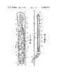
- FIG. 2is a side elevational view of the overall underground boring apparatus disclosed herein and designed in accordance with a preferred embodiment of the present invention
- FIG. 1is an enlarged, partially broken away side elevational view illustrating a portion of the system shown in FIG. 2, specifically its boring head and associated steering section;
- FIG. 3is a cross sectional view of the steering section illustrated in FIG. 2, and taken generally along line 3--3 in FIG. 2;
- FIG. 4is a view similar to FIG. 3 but illustrating the steering section of the overall apparatus in a different operating position
- FIG. 5is also a view similar to FIG. 3 but illustrating the steering section of the overall apparatus in still a different operating position
- FIG. 6is an enlarged diagrammatic view depicting a portion of the steering section shown in FIG. 2 and specifically illustrating how the boring head is caused to turn in a controlled fashion;
- FIG. 7is a view similar to FIG. 6 but illustrating how the steering section of the overall apparatus causes the boring head to remain in a straight line path of movement.
- FIG. 1illustrates an overall underground boring system generally designated by the reference numeral 10.
- This systemincludes a forwardmost boring head 12 and an adjacent steering section 16 which is designed in accordance with the present invention and which will be described in detail hereinafter.
- steering section 16serves to guide boring head 12 along either a straight line path or a curved path as the boring head moves through the ground or earth 18.
- the various components making up overall system 10 including body head 12are conventional or may be readily provided by those with ordinary skill in the art. These components include means for moving head 12 and its associated steering section 16 in a generally forward direction through earth 18, for example, cooperating pull and push type of soil gripping arrangements 20 and 22, respectively. These arrangements are disposed behind boring head 12 and steering section 16 within the underground passageway 24 made by the boring head and cooperate with one another and with the wall of the passageway to continuously thrust the boring head and steering section in a generally forward direction.
- the boring headitself is preferably of the reciprocating, high impact type (as will be described briefly in conjunction with FIG. 2 hereinafter) and also preferably directs one or more jets of water 26 out its front end.
- overall system 10may require both a supply of air under pressure and a suitable air control valve or the like generally indicated at 28 for causing the boring head to reciprocate pneumatically.
- Both the supply of air and a supply of water for jets 26could be provided at a common location above ground generally indicated at 30.
- suitable air and water conduits extending between the underground components and location 30would be necessary.
- suitable control conduits for operating arrangements 20 and 22 from location 30would be necessary.
- These various conduitsare indicated generally at 32.
- the various components which make up the train of components within passageway 24may be interconnected together by suitable coupling members 34.
- the various components making up overall boring system 10are conventional or may be readily provided by those with ordinary skill in the art. These components may or may not include a reciprocating type of boring head and/or one which includes water jets 26, they may or may not include the particular gripping arrangements as shown, that is, gripping arrangements 20 and 22, and they may or may not include other associated components.
- the overall systemis one which causes the boring head and the steering section to move in a generally forward direction as the boring head provides the passageway 24. Since these various components (with the exception of the steering section) do not form part of the present invention, they will not be described any further, although the boring head 12 will be described to the extent necessary to understand the way in which it cooperates with the steering section in accordance with the present invention.
- boring head 12 and steering section 16As seen in this latter figure, the boring head tapers outwardly and rearwardly from its forwardmost end to a rearwardly extending, cylindrical body 38 which defines the maximum outermost diameter of the boring head.
- An elongated shaft arrangement generally indicated at 40 and smaller in cross sectional configuration than body 38is fixedly connected at its front end to and extends rearwardly from the back end of the boring head.
- Arrangement 40serves to contain an anvil 42 and cooperating hammer 44 for causing the boring head to reciprocate.
- a suitable supply of air controlled by means of previously recited valve 28is provided through arrangement 40 for operating the anvil and hammer.
- the shaft arrangementalso includes a central passageway 46 in fluid communication with an incoming high pressure water hose 48 for directing water under pressure from its source at location 30 through boring head 12 and out its front end in the form of one or more high pressure jets 26.
- the overall shaft arrangement 40not only serves as a means of supporting boring head 12 and as a means for containing the various components just recited but also as a component of steering section 16 for causing the boring head to either move along a curved path or in a straight line.
- steering section 16is shown including an outermost, elongated tubular housing 50 having a front end 52 and a rearwardmost end 54.
- the outermost surface of housing 50tapers outwardly from these opposite ends to a central point 56 therebetween such that the cross sectional size of the tubular housing at this central point is approximately the same size as the maximum cross sectional configuration of the boring head.
- shaft arrangement 40extends partially into housing 50 through its front end.
- An outer collar 58is disposed around an external section of the shaft arrangement and immediately in front of housing 50 so as to prevent the latter from sliding further into the housing.
- a second collar 60 located within housing 50is fixedly disposed around an internal section of shaft arrangement 40 adjacent the front end 52 of the housing. This latter collar includes an outermost surface 62 which is formed from a segment of a sphere. Surface 62 engages a cooperating inner surface segment of housing 50 for supporting shaft arrangement 40 and therefore boring head 12 for limited pivotal movement relative to housing 50.
- shaft arrangement 40is able to pivot about any axis which is coextensive with any diameter forming part of surface 62.
- boring head 12is movable relative to housing 50 to any point on a circle perpendicular to and radially outward of (but concentric with) housing 50.
- boring head 12The purpose for the pivotal movement of boring head 12 is to allow it to move in a curved path as it is driven in a generally forward direction through the earth. More specifically, so long as shaft arrangement 40 is maintained in coaxial relationship with housing 50, the entire train of components including the boring head will move along a generally straight line path. By pivoting shaft arrangement 40 and therefore boring head 12 relative to the housing, the boring head and therefore the entire train of underground components are caused to turn in the direction of the pivot. For example, as illustrated in FIG. 1, when the front end of the shaft arrangement and the boring head are pivoted downward relative to the housing, the entire train of components will curve in a downward direction. On the other hand, as illustrated in FIG.
- the boring headcan be made to make sharper turns than would be possible using a non-tapered housing, that is, one having a uniform cross section along its entire length.
- a non-tapered housingthat is, one having a uniform cross section along its entire length.
- FIG. 2As seen there, as the front end of shaft arrangement 40 is pivoted upwards and its rear end moves downwards, the front end of housing 50 is caused to move downwards while its rear end moves upwards, all within passage 24. This is possible because the maximum cross section of the passageway is approximately equal to the maximum diameter of boring head 12 and therefore approximately equal to the maximum diameter of the housing at central point 56. Therefore, since the front and rear ends of the housing are smaller in cross section there is room within the passageway to allow these ends to pivot.
- the housingis allowed to pivot in opposition to the pivoting motion of shaft arrangement 40, it reduces the radius of curvature defining the turn made by the boring head over what the radius would be if only the shaft arrangement were to pivot.
- steering section 16includes an arrangement 64 of piston/cylinder units disposed within housing 50 directly behind the back end of shaft arrangement 40.
- Arrangement 64includes four cylinder openings 66 and associated pistons 68 which extend parallel with and which are equally circumferentially spaced around the axis of housing 56.
- the piston/cylinder unitsmay be operated electrically or pneumatically, they are preferably individually operated hydraulically in the manner to be described hereinafter with respect to FIGS. 6 and 7. For the moment, it suffices to say that each piston is caused to move between a retracted position within its associated cylinder opening and an extended position closer to the front end of the housing.
- Each pistonmay be individually moved from its retracted position to its extended position (while the others remain in their retracted positions), two adjacent pistons may be moved simultaneously to their extended positions, or all four pistons may be moved simultaneously to extended positions.
- a source of hydraulic fluid and suitable control means disposed at location 30may be provided for accomplishing this in the manner to be described with respect to FIGS. 6 and 7.
- each piston 68carries a shaft engaging member 70 having an inwardly and rearwardly extending surface 72.
- the rearwardmost end of shaft 40includes a rearwardly and inwardly tapering circumferential surface 74 which is adapted to engage the individual surfaces 72 of members 70 when associated pistons are in their extended positions.
- FIG. 3shows a top member 70a in its extended position while the other members 70b, 70c, and 70d (see FIG. 5) remain in their retracted positions. This causes the top member to engage surface 74 in a way which causes the bottom end of shaft arrangement 40 to pivot downward and the top end and boring head 12 to pivot upwards.
- FIG. 3shows a top member 70a in its extended position while the other members 70b, 70c, and 70d (see FIG. 5) remain in their retracted positions. This causes the top member to engage surface 74 in a way which causes the bottom end of shaft arrangement 40 to pivot downward and the top end and boring head 12 to pivot upwards.
- FIG. 5shows all four of the members 70a, 70b, 70c and 70d in equally extended positions. As will be seen hereinafter, this causes the shaft arrangement to be maintained in coaxial relaionship with the housing 50 for maintaining movement of the boring head in a straight line path.
- each of the cylinders 68is caused to move between its extended and retracted positions.
- Thisis shown in the figures diagrammatically in order to fully understand the present invention. It is to be understood that the various means to be described with regard to these latter figures are incorporated in one form or another in system 10 as it actually exists.
- two of the four cylinder openings 66(66a,66c for consistency) are shown in a common cylinder body 76 having a through opening for the passage of previously described hose 48 and other necessary components.
- the back end of each opening 66includes an inlet port 80 for hydraulic fluid.
- each inlet portis maintained and in fluid communication with an associated hydraulic fluid inlet hose 82 which extends back to the source of hydraulic fluid at location 30.
- each cylinder opening 66also includes a side port 84 which opens out into a common manifold 86 for all of the side ports.
- a single hydraulic fluid return hose 88extends between manifold 86 and the source of hydraulic fluid at location 30.
- a set of controlsare provided for operating the arrangement of piston/cylinder units. These controls include a suitable valve associated with each hydraulic fluid line 82 for either opening or closing the line to the source of hydraulic fluid and a single valve for either opening or closing return line 88 to the fluid source.
- a suitable valveassociated with each hydraulic fluid line 82 for either opening or closing the line to the source of hydraulic fluid
- a single valvefor either opening or closing return line 88 to the fluid source.
Landscapes
- Engineering & Computer Science (AREA)
- Life Sciences & Earth Sciences (AREA)
- Geology (AREA)
- Mining & Mineral Resources (AREA)
- Physics & Mathematics (AREA)
- Environmental & Geological Engineering (AREA)
- Fluid Mechanics (AREA)
- General Life Sciences & Earth Sciences (AREA)
- Geochemistry & Mineralogy (AREA)
- Mechanical Engineering (AREA)
- Earth Drilling (AREA)
Abstract
Description
Claims (8)
Priority Applications (1)
| Application Number | Priority Date | Filing Date | Title |
|---|---|---|---|
| US06/303,585US4396073A (en) | 1981-09-18 | 1981-09-18 | Underground boring apparatus with controlled steering capabilities |
Applications Claiming Priority (1)
| Application Number | Priority Date | Filing Date | Title |
|---|---|---|---|
| US06/303,585US4396073A (en) | 1981-09-18 | 1981-09-18 | Underground boring apparatus with controlled steering capabilities |
Publications (1)
| Publication Number | Publication Date |
|---|---|
| US4396073Atrue US4396073A (en) | 1983-08-02 |
Family
ID=23172765
Family Applications (1)
| Application Number | Title | Priority Date | Filing Date |
|---|---|---|---|
| US06/303,585Expired - Fee RelatedUS4396073A (en) | 1981-09-18 | 1981-09-18 | Underground boring apparatus with controlled steering capabilities |
Country Status (1)
| Country | Link |
|---|---|
| US (1) | US4396073A (en) |
Cited By (24)
| Publication number | Priority date | Publication date | Assignee | Title |
|---|---|---|---|---|
| US4823888A (en)* | 1986-12-30 | 1989-04-25 | Smet Nic H W | Apparatus for making a subterranean tunnel |
| US4938297A (en)* | 1987-07-25 | 1990-07-03 | Paul Schmidt | Ram boring machine |
| EP0397323A1 (en)* | 1989-05-08 | 1990-11-14 | Cherrington Corporation | Jet bit with onboard deviation means |
| US4974688A (en)* | 1989-07-11 | 1990-12-04 | Public Service Company Of Indiana, Inc. | Steerable earth boring device |
| US4974687A (en)* | 1988-03-28 | 1990-12-04 | Kayes Allan G | Soil displacement hammer |
| EP0401191A1 (en)* | 1989-05-31 | 1990-12-05 | Marc Jozef Maria Smet | Steerable drilling mole |
| US4993503A (en)* | 1990-03-27 | 1991-02-19 | Electric Power Research Institute | Horizontal boring apparatus and method |
| EP0428181A1 (en)* | 1985-04-05 | 1991-05-22 | Gas Research Institute | Percussion tool for drilling holes in the soil |
| WO1991011646A1 (en)* | 1990-01-24 | 1991-08-08 | Johnson Howard E | Utility tunneling method and apparatus |
| WO1991008370A3 (en)* | 1989-11-23 | 1991-11-14 | Bergh Johannes W H Den | Device for steering the foremost part of a drill pipe |
| EP0403078A3 (en)* | 1989-06-14 | 1991-11-27 | Underground Technologies Inc | Method and apparatus for directional drilling |
| BE1003327A4 (en)* | 1990-01-15 | 1992-02-25 | Smet Marc Jozef Maria | STEERABLE BOTTOM DRILLS. |
| BE1003500A3 (en)* | 1987-12-01 | 1992-04-07 | Smet Nic Hilde Walter | Turbine drill device |
| FR2671130A1 (en)* | 1990-12-28 | 1992-07-03 | Inst Francais Du Petrole | DEVICE COMPRISING TWO ELEMENTS ARTICULATED IN A PLANE, APPLIED TO DRILLING EQUIPMENT. |
| EP0497405A1 (en)* | 1991-01-28 | 1992-08-05 | Marc Jozef Maria Smet | Steerable drill head |
| US5322391A (en)* | 1992-09-01 | 1994-06-21 | Foster-Miller, Inc. | Guided mole |
| US5350254A (en)* | 1993-11-22 | 1994-09-27 | Foster-Miller, Inc. | Guided mole |
| US5597046A (en)* | 1995-04-12 | 1997-01-28 | Foster-Miller, Inc. | Guided mole |
| US5778991A (en)* | 1996-03-04 | 1998-07-14 | Vermeer Manufacturing Company | Directional boring |
| US6357537B1 (en) | 2000-03-15 | 2002-03-19 | Vermeer Manufacturing Company | Directional drilling machine and method of directional drilling |
| US6491115B2 (en) | 2000-03-15 | 2002-12-10 | Vermeer Manufacturing Company | Directional drilling machine and method of directional drilling |
| RU2209889C1 (en)* | 2001-11-14 | 2003-08-10 | Государственное научное учреждение Всероссийский научно-исследовательский институт гидротехники и мелиорации им. А.Н. Костякова | Device for laying underground service lines in water- logged grounds |
| US20100025115A1 (en)* | 2006-05-19 | 2010-02-04 | Spyro Kotsonis | Directional control drilling system |
| CN109736700A (en)* | 2019-03-25 | 2019-05-10 | 贵州航天天马机电科技有限公司 | A kind of frozen soil reacting cycle Bidirectional cutting churn drilling tools |
Citations (9)
| Publication number | Priority date | Publication date | Assignee | Title |
|---|---|---|---|---|
| US2271005A (en)* | 1939-01-23 | 1942-01-27 | Dow Chemical Co | Subterranean boring |
| US2345766A (en)* | 1940-12-02 | 1944-04-04 | Eastman Oil Well Survey Co | Deflecting tool |
| US2891769A (en)* | 1955-05-02 | 1959-06-23 | Directional Engineering Compan | Directional drilling tool |
| US3043381A (en)* | 1960-05-05 | 1962-07-10 | Jr Branch M Mcneely | Means for controlling directional deviations in a well bore |
| US3138213A (en)* | 1954-06-24 | 1964-06-23 | Orpha B Brandon | Method and apparatus for vibratory drilling |
| US3326008A (en)* | 1965-04-01 | 1967-06-20 | Baran Paul | Electrical gopher |
| US3677354A (en)* | 1970-12-03 | 1972-07-18 | Alexandr Dmitrievich Kostylev | Device for stabilizing the course of the tunnelling element |
| US4046204A (en)* | 1975-11-25 | 1977-09-06 | Agency Of Industrial Science & Technology | Controlled directional drilling tool |
| US4095655A (en)* | 1975-10-14 | 1978-06-20 | Still William L | Earth penetration |
- 1981
- 1981-09-18USUS06/303,585patent/US4396073A/ennot_activeExpired - Fee Related
Patent Citations (9)
| Publication number | Priority date | Publication date | Assignee | Title |
|---|---|---|---|---|
| US2271005A (en)* | 1939-01-23 | 1942-01-27 | Dow Chemical Co | Subterranean boring |
| US2345766A (en)* | 1940-12-02 | 1944-04-04 | Eastman Oil Well Survey Co | Deflecting tool |
| US3138213A (en)* | 1954-06-24 | 1964-06-23 | Orpha B Brandon | Method and apparatus for vibratory drilling |
| US2891769A (en)* | 1955-05-02 | 1959-06-23 | Directional Engineering Compan | Directional drilling tool |
| US3043381A (en)* | 1960-05-05 | 1962-07-10 | Jr Branch M Mcneely | Means for controlling directional deviations in a well bore |
| US3326008A (en)* | 1965-04-01 | 1967-06-20 | Baran Paul | Electrical gopher |
| US3677354A (en)* | 1970-12-03 | 1972-07-18 | Alexandr Dmitrievich Kostylev | Device for stabilizing the course of the tunnelling element |
| US4095655A (en)* | 1975-10-14 | 1978-06-20 | Still William L | Earth penetration |
| US4046204A (en)* | 1975-11-25 | 1977-09-06 | Agency Of Industrial Science & Technology | Controlled directional drilling tool |
Cited By (33)
| Publication number | Priority date | Publication date | Assignee | Title |
|---|---|---|---|---|
| EP0428181A1 (en)* | 1985-04-05 | 1991-05-22 | Gas Research Institute | Percussion tool for drilling holes in the soil |
| US4823888A (en)* | 1986-12-30 | 1989-04-25 | Smet Nic H W | Apparatus for making a subterranean tunnel |
| US4938297A (en)* | 1987-07-25 | 1990-07-03 | Paul Schmidt | Ram boring machine |
| BE1003500A3 (en)* | 1987-12-01 | 1992-04-07 | Smet Nic Hilde Walter | Turbine drill device |
| US4974687A (en)* | 1988-03-28 | 1990-12-04 | Kayes Allan G | Soil displacement hammer |
| AU618470B2 (en)* | 1989-05-08 | 1991-12-19 | Cherrington Corporation | Jet bit with onboard deviation means |
| EP0397323A1 (en)* | 1989-05-08 | 1990-11-14 | Cherrington Corporation | Jet bit with onboard deviation means |
| EP0401191A1 (en)* | 1989-05-31 | 1990-12-05 | Marc Jozef Maria Smet | Steerable drilling mole |
| BE1003865A3 (en)* | 1989-05-31 | 1992-06-30 | Smet Marc Jozef Maria | Steerable BOORMOL. |
| EP0403078A3 (en)* | 1989-06-14 | 1991-11-27 | Underground Technologies Inc | Method and apparatus for directional drilling |
| US4974688A (en)* | 1989-07-11 | 1990-12-04 | Public Service Company Of Indiana, Inc. | Steerable earth boring device |
| WO1991008370A3 (en)* | 1989-11-23 | 1991-11-14 | Bergh Johannes W H Den | Device for steering the foremost part of a drill pipe |
| BE1003327A4 (en)* | 1990-01-15 | 1992-02-25 | Smet Marc Jozef Maria | STEERABLE BOTTOM DRILLS. |
| WO1991011646A1 (en)* | 1990-01-24 | 1991-08-08 | Johnson Howard E | Utility tunneling method and apparatus |
| US4993503A (en)* | 1990-03-27 | 1991-02-19 | Electric Power Research Institute | Horizontal boring apparatus and method |
| WO1992012324A1 (en)* | 1990-12-28 | 1992-07-23 | Institut Français Du Petrole | Device comprising two elements hinged in a plane, used in drilling equipment |
| FR2671130A1 (en)* | 1990-12-28 | 1992-07-03 | Inst Francais Du Petrole | DEVICE COMPRISING TWO ELEMENTS ARTICULATED IN A PLANE, APPLIED TO DRILLING EQUIPMENT. |
| EP0497405A1 (en)* | 1991-01-28 | 1992-08-05 | Marc Jozef Maria Smet | Steerable drill head |
| BE1005244A3 (en)* | 1991-01-28 | 1993-06-08 | Smet Marc Jozef Maria | Steerable BOORMOL. |
| US5279373A (en)* | 1991-01-28 | 1994-01-18 | Smet Marc J M | Controllable drill head |
| US5322391A (en)* | 1992-09-01 | 1994-06-21 | Foster-Miller, Inc. | Guided mole |
| JP3449722B2 (en) | 1993-11-22 | 2003-09-22 | フォスター ミラー インク | Drilling rig with improved guidance function |
| WO1995014878A1 (en)* | 1993-11-22 | 1995-06-01 | Foster-Miller, Inc. | Improved guided mole |
| US5350254A (en)* | 1993-11-22 | 1994-09-27 | Foster-Miller, Inc. | Guided mole |
| US5597046A (en)* | 1995-04-12 | 1997-01-28 | Foster-Miller, Inc. | Guided mole |
| US5778991A (en)* | 1996-03-04 | 1998-07-14 | Vermeer Manufacturing Company | Directional boring |
| US6357537B1 (en) | 2000-03-15 | 2002-03-19 | Vermeer Manufacturing Company | Directional drilling machine and method of directional drilling |
| US6491115B2 (en) | 2000-03-15 | 2002-12-10 | Vermeer Manufacturing Company | Directional drilling machine and method of directional drilling |
| RU2209889C1 (en)* | 2001-11-14 | 2003-08-10 | Государственное научное учреждение Всероссийский научно-исследовательский институт гидротехники и мелиорации им. А.Н. Костякова | Device for laying underground service lines in water- logged grounds |
| US20100025115A1 (en)* | 2006-05-19 | 2010-02-04 | Spyro Kotsonis | Directional control drilling system |
| US8191652B2 (en)* | 2006-05-19 | 2012-06-05 | Schlumberger Technology Corporation | Directional control drilling system |
| CN109736700A (en)* | 2019-03-25 | 2019-05-10 | 贵州航天天马机电科技有限公司 | A kind of frozen soil reacting cycle Bidirectional cutting churn drilling tools |
| CN109736700B (en)* | 2019-03-25 | 2021-04-20 | 贵州航天天马机电科技有限公司 | Frozen soil reverse circulation bidirectional cutting percussion drilling tool |
Similar Documents
| Publication | Publication Date | Title |
|---|---|---|
| US4396073A (en) | Underground boring apparatus with controlled steering capabilities | |
| US3168853A (en) | Hydraulic cylinder device | |
| US4295533A (en) | Pneumatically operated ram borer | |
| US4281723A (en) | Control system for a drilling apparatus | |
| NO130328B (en) | ||
| CA1167740A (en) | Hydraulically operated impact device | |
| US4039033A (en) | Hydraulic rock drill | |
| US3814324A (en) | Propulsion nozzle and actuator system employed therein | |
| TW343168B (en) | A pneumatic actuator device | |
| US6371220B1 (en) | Pneumatically reversible ram drilling tool | |
| US4609052A (en) | Pneumatically operated burrowing tool | |
| CN101025128A (en) | Axial symmetric vector spray-pipe A9 action emergency resetting hydraulic system | |
| US4060221A (en) | Double-acting hydraulic cylinder having two pistons arranged for coaxial movement relative thereto | |
| JPS6038520B2 (en) | Cartridge injection device for ceiling bolt attachment device | |
| NL1000971C2 (en) | Plow Turning Device. | |
| US5960892A (en) | Automatically driven pile driver drilling device | |
| US4073393A (en) | Control system for refuse packer assembly | |
| US4126155A (en) | Valve piston for hydraulic control valve | |
| US4114700A (en) | Pneumatic apparatus of the percussive type | |
| AU641778B2 (en) | Soil displacement hammer with reversing mechanism | |
| GB1569569A (en) | Hydraulic pressure generation apparatus | |
| US4397175A (en) | Apparatus for controlling the movement of a reciprocatory hydraulically driven element | |
| FI87831C (en) | Vertical drilling boom | |
| US4821813A (en) | Percussion drilling apparatus | |
| JPS5914395B2 (en) | Adjustable pitch propeller blade adjustment device |
Legal Events
| Date | Code | Title | Description |
|---|---|---|---|
| AS | Assignment | Owner name:FLOW INDUSTRIES, INC. KENT WA A CORP. OF WA Free format text:ASSIGNMENT OF ASSIGNORS INTEREST.;ASSIGNORS:REICHMAN, JAMES M.;KELLEY, DOUGLAS P.;REEL/FRAME:004005/0811 Effective date:19810914 Owner name:FLOW AND ELECTRIC POWER RESEARCH INSTITUTE, INC., Free format text:ASSIGNMENT OF ASSIGNORS INTEREST.;ASSIGNOR:FLOW INDUSTRIES, INC.;REEL/FRAME:004005/0814 Effective date:19810914 | |
| MAFP | Maintenance fee payment | Free format text:PAYMENT OF MAINTENANCE FEE, 4TH YEAR, PL 96-517 (ORIGINAL EVENT CODE: M170); ENTITY STATUS OF PATENT OWNER: SMALL ENTITY Year of fee payment:4 | |
| FEPP | Fee payment procedure | Free format text:MAINTENANCE FEE REMINDER MAILED (ORIGINAL EVENT CODE: REM.); ENTITY STATUS OF PATENT OWNER: SMALL ENTITY | |
| LAPS | Lapse for failure to pay maintenance fees | ||
| STCH | Information on status: patent discontinuation | Free format text:PATENT EXPIRED DUE TO NONPAYMENT OF MAINTENANCE FEES UNDER 37 CFR 1.362 | |
| FP | Lapsed due to failure to pay maintenance fee | Effective date:19910804 |