US4396047A - Electric wood splitter - Google Patents
Electric wood splitterDownload PDFInfo
- Publication number
- US4396047A US4396047AUS06/269,375US26937581AUS4396047AUS 4396047 AUS4396047 AUS 4396047AUS 26937581 AUS26937581 AUS 26937581AUS 4396047 AUS4396047 AUS 4396047A
- Authority
- US
- United States
- Prior art keywords
- jack screw
- screw shafts
- wood
- hand threaded
- shafts
- Prior art date
- Legal status (The legal status is an assumption and is not a legal conclusion. Google has not performed a legal analysis and makes no representation as to the accuracy of the status listed.)
- Expired - Fee Related
Links
- 239000002023woodSubstances0.000titleclaimsabstractdescription20
- 230000008878couplingEffects0.000claims1
- 238000010168coupling processMethods0.000claims1
- 238000005859coupling reactionMethods0.000claims1
- 238000004519manufacturing processMethods0.000description2
- 239000000463materialSubstances0.000description2
- 230000005611electricityEffects0.000description1
- 238000000034methodMethods0.000description1
- 239000007787solidSubstances0.000description1
Images
Classifications
- B—PERFORMING OPERATIONS; TRANSPORTING
- B27—WORKING OR PRESERVING WOOD OR SIMILAR MATERIAL; NAILING OR STAPLING MACHINES IN GENERAL
- B27L—REMOVING BARK OR VESTIGES OF BRANCHES; SPLITTING WOOD; MANUFACTURE OF VENEER, WOODEN STICKS, WOOD SHAVINGS, WOOD FIBRES OR WOOD POWDER
- B27L7/00—Arrangements for splitting wood
Definitions
- This inventionrelates generally to power driven devices for splitting firewood or the like, and deals more particularly with an electrically driven device having a unique configuration for movably supporting the wood splitting blade.
- the general object of the present inventionis to provide an inexpensive wood splitting device of the type adapted to be driven from a readily available source of energy such as electricity for example, and it is a feature of the present invention that the device is very economical, such a device being well adapted to low cost high quantity mass production.
- a wood splitting device of the present inventionincludes electric motor means, a worm gear provided on the motor's drive shaft, parallel left and right hand threaded screw shafts oriented in a plane perpendicular to the axis of the motors drive shaft and having two spur gears meshing with this single worm gear to achieve counter-rotation of these left and right hand threaded shafts.
- Captured left and right hand threaded nutsare provided in the wood splitting blade itself so as to achieve linear motion of the blade in response to rotation of the left and right hand threaded jack screw shafts.
- a reversing switchis provided for achieving return movement of the blade and a shield is provided between the wood to be split and the jack screws to protect these threaded screws from the material being split due to splintering or the like of the wood being split.
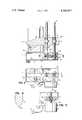
- FIG. 1is a vertical sectional view taken generally on the 1--1 of FIG. 2.
- FIG. 2is a top plan view of the apparatus illustrated in FIG. 1.
- FIG. 3is a horizontal sectional view taken generally on the line 3--3 of FIG. 1.
- FIG. 4is a sectional view taken on the line 4--4 of FIG. 2.
- FIG. 1shows a wood splitting device constructed in accordance with the present invention, and said device includes a wood splitting blade 10, shown in intermediate position in the process of splitting a log L.
- the logis supported on a base 12 comprising a box-like frame consisting of a generally horizontal upper plate 12a welded by means of side walls to a bottom plate 12b so as to provide a convenient structure for supporting two vertically extending jack screws 14 and 16 rotatably mounted in spaced sets of bearings 18 and 20.
- These jack screws 14 and 16are parallel to one another and oriented in a vertical plane through which the blade 10 is adapted to move as its cutting edge 10d splits the log L as shown.
- the lower ends of the jack screws 14 and 16carry spur gears 42 and 44, which gears 42 and 44 mesh with a worm gear 40 located between these spur gears 42 and 44 on the drive shaft 36 associated with electric motor M.
- the motor Mis held in the base 12 by a suitable means (not shown) and associated with the motor M is a reversing switch 32 which may also include means for selectively turning power to the motor M on and off.
- the motor Mis thus adapted to be electrically connected to a source of power by means of plug 34.
- the wood splitting blade 10includes a portion 10a having vertically oriented openings through which the jack screws 14 and 16 extend. Communicating with these cylindrical openings in the blade base portion 10a are rectangular openings 10a and 10b, which are adapted to retain left and right hand threaded nuts 46 and 48 respectively, as best shown in FIG. 1. These nuts 46 and 48 achieve vertical motion of the blade 10 in a response to counter-rotational motion of the jack screws 14 and 16.
- the generally square openings 10b and 10c for so supporting the nuts 46 and 48 respectivelyare illustrated to best advantage in FIGS. 1 and 2.
- the device of the present inventionis well adapted to split logs, such as shown at L in the drawing, by reason of vertical downward motion of the blade 10 in response to rotation of the motor M and its drive shaft 36 in a particular direction. Reversing the motor M, through switch 32, will permit return movement of the blade 10 so as to allow splitting of further workpieces or logs L.
- the blade 10may be a solid member, as shown in FIG. 4, with a lower cutting edge 10d, or in the alternative may comprise a welded up structure (not shown) where it is desired to manufacture the present apparatus for use in splitting lighter weight logs, or to permit the blade 10 to be made of lighter weight material for reducing the cost of the device itself.
- the drive shaft 36may extend across the box-like frame 12 in order to permit the free end portion 36a of the drive shaft 36 to be supported at its free end portion 36a in an opening as suggested at 38 in this view.
Landscapes
- Life Sciences & Earth Sciences (AREA)
- Engineering & Computer Science (AREA)
- Wood Science & Technology (AREA)
- Forests & Forestry (AREA)
- Debarking, Splitting, And Disintegration Of Timber (AREA)
Abstract
Description
Claims (4)
Priority Applications (1)
| Application Number | Priority Date | Filing Date | Title |
|---|---|---|---|
| US06/269,375US4396047A (en) | 1981-06-01 | 1981-06-01 | Electric wood splitter |
Applications Claiming Priority (1)
| Application Number | Priority Date | Filing Date | Title |
|---|---|---|---|
| US06/269,375US4396047A (en) | 1981-06-01 | 1981-06-01 | Electric wood splitter |
Publications (1)
| Publication Number | Publication Date |
|---|---|
| US4396047Atrue US4396047A (en) | 1983-08-02 |
Family
ID=23026978
Family Applications (1)
| Application Number | Title | Priority Date | Filing Date |
|---|---|---|---|
| US06/269,375Expired - Fee RelatedUS4396047A (en) | 1981-06-01 | 1981-06-01 | Electric wood splitter |
Country Status (1)
| Country | Link |
|---|---|
| US (1) | US4396047A (en) |
Cited By (19)
| Publication number | Priority date | Publication date | Assignee | Title |
|---|---|---|---|---|
| US4516303A (en)* | 1983-03-16 | 1985-05-14 | Kloster Kenneth D | Spring compressor |
| USD334755S (en) | 1991-12-05 | 1993-04-13 | Marken Enterprises, Inc. | Log splitter |
| DE29722633U1 (en)* | 1997-12-22 | 1998-03-12 | Südharzer Maschinenbau GmbH, 99734 Nordhausen | Device for splitting wood |
| US20030111656A1 (en)* | 2001-12-17 | 2003-06-19 | Dura Global Technologies, Inc. | Multiple screw jack |
| US7458562B1 (en)* | 2007-06-28 | 2008-12-02 | Hiwin Mikrosystem Corp. | Extendible and retractable actuator |
| US20110138948A1 (en)* | 2009-07-22 | 2011-06-16 | Jimenez Omar F | Coaxial screw gear sleeve mechanism |
| US20130237859A1 (en)* | 2010-11-29 | 2013-09-12 | Canon Kabushiki Kaisha | Apparatus |
| US20140008905A1 (en)* | 2010-12-21 | 2014-01-09 | Schaeffler Technologies AG & Co. KG | Support device for work vehicles |
| US8636746B2 (en) | 2009-12-31 | 2014-01-28 | Spinex Tec, Llc | Methods and apparatus for insertion of vertebral body distraction and fusion devices |
| US8906100B2 (en) | 2008-12-31 | 2014-12-09 | Ex Technology, Llc | Methods and apparatus for vertebral body distraction and fusion employing flexure members |
| US8940049B1 (en) | 2014-04-01 | 2015-01-27 | Ex Technology, Llc | Expandable intervertebral cage |
| US20160280518A1 (en)* | 2015-03-25 | 2016-09-29 | K-Line Industries, Inc. | Jack system |
| US9486328B2 (en) | 2014-04-01 | 2016-11-08 | Ex Technology, Llc | Expandable intervertebral cage |
| US9867717B2 (en) | 2009-03-19 | 2018-01-16 | Ex Technology, Llc | Stable device for intervertebral distraction and fusion |
| US11234835B2 (en) | 2019-03-05 | 2022-02-01 | Octagon Spine Llc | Transversely expandable minimally invasive intervertebral cage |
| US11497622B2 (en) | 2019-03-05 | 2022-11-15 | Ex Technology, Llc | Transversely expandable minimally invasive intervertebral cage and insertion and extraction device |
| DE102021112730A1 (en) | 2021-05-17 | 2022-11-17 | Joachim Albrecht | log splitting device |
| US12011365B2 (en) | 2022-07-18 | 2024-06-18 | Octagon Spine Llc | Transversely expandable minimally invasive inter vertebral cage |
| US12097126B2 (en) | 2021-09-29 | 2024-09-24 | Ex Technology, Llc | Expandable intervertebral cage |
Citations (4)
| Publication number | Priority date | Publication date | Assignee | Title |
|---|---|---|---|---|
| US1283195A (en)* | 1918-03-06 | 1918-10-29 | Albert Hunter | Log-splitting machine. |
| US3514090A (en)* | 1967-07-19 | 1970-05-26 | Pandjiris Weldment Co | Workpiece positioner |
| US4121636A (en)* | 1977-07-21 | 1978-10-24 | James Robert G | Adaptor for splitting logs |
| US4141395A (en)* | 1977-08-04 | 1979-02-27 | Arzt Allan H | Log splitter |
- 1981
- 1981-06-01USUS06/269,375patent/US4396047A/ennot_activeExpired - Fee Related
Patent Citations (4)
| Publication number | Priority date | Publication date | Assignee | Title |
|---|---|---|---|---|
| US1283195A (en)* | 1918-03-06 | 1918-10-29 | Albert Hunter | Log-splitting machine. |
| US3514090A (en)* | 1967-07-19 | 1970-05-26 | Pandjiris Weldment Co | Workpiece positioner |
| US4121636A (en)* | 1977-07-21 | 1978-10-24 | James Robert G | Adaptor for splitting logs |
| US4141395A (en)* | 1977-08-04 | 1979-02-27 | Arzt Allan H | Log splitter |
Cited By (39)
| Publication number | Priority date | Publication date | Assignee | Title |
|---|---|---|---|---|
| US4516303A (en)* | 1983-03-16 | 1985-05-14 | Kloster Kenneth D | Spring compressor |
| USD334755S (en) | 1991-12-05 | 1993-04-13 | Marken Enterprises, Inc. | Log splitter |
| DE29722633U1 (en)* | 1997-12-22 | 1998-03-12 | Südharzer Maschinenbau GmbH, 99734 Nordhausen | Device for splitting wood |
| US20030111656A1 (en)* | 2001-12-17 | 2003-06-19 | Dura Global Technologies, Inc. | Multiple screw jack |
| US6722635B2 (en)* | 2001-12-17 | 2004-04-20 | Atwood Mobile Products, Inc. | Multiple screw jack |
| US7458562B1 (en)* | 2007-06-28 | 2008-12-02 | Hiwin Mikrosystem Corp. | Extendible and retractable actuator |
| US8906100B2 (en) | 2008-12-31 | 2014-12-09 | Ex Technology, Llc | Methods and apparatus for vertebral body distraction and fusion employing flexure members |
| US10060469B2 (en) | 2008-12-31 | 2018-08-28 | Ex Technology, Llc | Flexible joint arrangement incorporating flexure members |
| US9445917B2 (en) | 2008-12-31 | 2016-09-20 | Ex Technology, Llc | Methods and apparatus for expandable medical device employing flexure members |
| US9381092B2 (en) | 2008-12-31 | 2016-07-05 | Ex Technology, Llc | Flexible joint arrangement incorporating flexure members |
| US9867717B2 (en) | 2009-03-19 | 2018-01-16 | Ex Technology, Llc | Stable device for intervertebral distraction and fusion |
| US10369008B2 (en) | 2009-07-22 | 2019-08-06 | Spinex Tec Llc | Medical device employing a coaxial screw gear sleeve mechanism |
| US11612496B2 (en) | 2009-07-22 | 2023-03-28 | Spinex Tec Llc | Medical device employing a coaxial screw gear sleeve mechanism |
| US9358125B2 (en)* | 2009-07-22 | 2016-06-07 | Spinex Tec, Llc | Coaxial screw gear sleeve mechanism |
| US8771360B2 (en) | 2009-07-22 | 2014-07-08 | Spinex Tec, Llc | Methods and apparatuses for vertebral body distraction and fusion employing a coaxial screw gear sleeve mechanism |
| US11026804B2 (en) | 2009-07-22 | 2021-06-08 | Spinex Tec, Llc | Coaxial screw gear sleeve mechanism |
| US9474626B2 (en) | 2009-07-22 | 2016-10-25 | Spinex Tec Llc | Methods and apparatuses for vertebral body distraction and fusion employing a coaxial screw gear sleeve mechanism |
| US20110138948A1 (en)* | 2009-07-22 | 2011-06-16 | Jimenez Omar F | Coaxial screw gear sleeve mechanism |
| US10117757B2 (en) | 2009-07-22 | 2018-11-06 | Spinex Tec, Llc | Coaxial screw gear sleeve mechanism |
| US8636746B2 (en) | 2009-12-31 | 2014-01-28 | Spinex Tec, Llc | Methods and apparatus for insertion of vertebral body distraction and fusion devices |
| US20130237859A1 (en)* | 2010-11-29 | 2013-09-12 | Canon Kabushiki Kaisha | Apparatus |
| US20140008905A1 (en)* | 2010-12-21 | 2014-01-09 | Schaeffler Technologies AG & Co. KG | Support device for work vehicles |
| US8932302B2 (en) | 2011-07-22 | 2015-01-13 | Spinex Tec, Llc | Methods and apparatus for insertion of vertebral body distraction and fusion devices |
| US9498270B2 (en) | 2011-07-22 | 2016-11-22 | SpineX Tee, LLC | Methods and apparatus for insertion of vertebral body distraction and fusion devices |
| US10052214B2 (en) | 2014-04-01 | 2018-08-21 | Ex Technology, Llc | Expandable intervertebral cage |
| US11471301B2 (en) | 2014-04-01 | 2022-10-18 | Ex Technology, Llc | Expandable intervertebral cage |
| US9668879B2 (en) | 2014-04-01 | 2017-06-06 | Ex Technology, Llc | Expandable intervertebral cage |
| US9486328B2 (en) | 2014-04-01 | 2016-11-08 | Ex Technology, Llc | Expandable intervertebral cage |
| US10687963B2 (en) | 2014-04-01 | 2020-06-23 | Ex Technology, Llc | Expandable intervertebral cage |
| US12156819B2 (en) | 2014-04-01 | 2024-12-03 | Ex Technology, Llc | Expandable inter vertebral cage |
| US8940049B1 (en) | 2014-04-01 | 2015-01-27 | Ex Technology, Llc | Expandable intervertebral cage |
| US9758359B2 (en)* | 2015-03-25 | 2017-09-12 | K-Line Industries, Inc. | Jack system |
| US20160280518A1 (en)* | 2015-03-25 | 2016-09-29 | K-Line Industries, Inc. | Jack system |
| US11497622B2 (en) | 2019-03-05 | 2022-11-15 | Ex Technology, Llc | Transversely expandable minimally invasive intervertebral cage and insertion and extraction device |
| US11234835B2 (en) | 2019-03-05 | 2022-02-01 | Octagon Spine Llc | Transversely expandable minimally invasive intervertebral cage |
| US11911292B2 (en) | 2019-03-05 | 2024-02-27 | Octagon Spine Llc | Transversely expandable minimally invasive intervertebral cage |
| DE102021112730A1 (en) | 2021-05-17 | 2022-11-17 | Joachim Albrecht | log splitting device |
| US12097126B2 (en) | 2021-09-29 | 2024-09-24 | Ex Technology, Llc | Expandable intervertebral cage |
| US12011365B2 (en) | 2022-07-18 | 2024-06-18 | Octagon Spine Llc | Transversely expandable minimally invasive inter vertebral cage |
Similar Documents
| Publication | Publication Date | Title |
|---|---|---|
| US4396047A (en) | Electric wood splitter | |
| CN115846748A (en) | Panel cutting device for power equipment | |
| AU545990B2 (en) | Mounting electrical devices | |
| CN112736718A (en) | Energy-concerving and environment-protective type electromechanical cubical switchboard | |
| US2983175A (en) | Foam glass shaping device | |
| CN217265431U (en) | Glass curtain wall cutting and processing device capable of being adjusted randomly | |
| GB1089687A (en) | Improvements in rotary scythe lawn mowers | |
| CN209319950U (en) | Decorative panel for building processing unit (plant) | |
| CN112809091A (en) | Linear cutting device for plane molybdenum target | |
| CN222360331U (en) | A board cutting device for wooden cabinet processing | |
| CN219758346U (en) | Electric power safety tool test fixture | |
| CN213859528U (en) | Positioning mechanism for cutting injection molding product | |
| CA1156131A (en) | Edger | |
| CN208788663U (en) | A sponge disc flat cutting machine | |
| ATE226493T1 (en) | MECHANICAL SHEARS FOR HOT CUTTING BILLETS OR METAL RODS | |
| CN215943217U (en) | A cutting equipment for wood | |
| CN219213762U (en) | Cutting and crushing device for rubber product renewable resources | |
| CN215094138U (en) | An environmentally friendly processing cutting saw | |
| CN211708240U (en) | Novel petroleum pipeline cutting machine | |
| CN214443523U (en) | Novel panel saw cuts device | |
| CN210678842U (en) | Cutting device is used in processing of conveyer belt | |
| CN211333635U (en) | Wood board cutting device for wood processing | |
| CN215094193U (en) | Furniture processing equipment with scrap recovery mechanism | |
| CN210116049U (en) | Numerical control gantry combined saw | |
| SU474068A1 (en) | Electrical Cable Cutter |
Legal Events
| Date | Code | Title | Description |
|---|---|---|---|
| MAFP | Maintenance fee payment | Free format text:PAYMENT OF MAINTENANCE FEE, 4TH YEAR, PL 96-517 (ORIGINAL EVENT CODE: M170); ENTITY STATUS OF PATENT OWNER: SMALL ENTITY Year of fee payment:4 | |
| FEPP | Fee payment procedure | Free format text:SURCHARGE FOR LATE PAYMENT, PL 96-517 (ORIGINAL EVENT CODE: M176); ENTITY STATUS OF PATENT OWNER: SMALL ENTITY | |
| MAFP | Maintenance fee payment | Free format text:PAYMENT OF MAINTENANCE FEE, 8TH YEAR, PL 96-517 (ORIGINAL EVENT CODE: M171); ENTITY STATUS OF PATENT OWNER: SMALL ENTITY Year of fee payment:8 | |
| FEPP | Fee payment procedure | Free format text:PAYOR NUMBER ASSIGNED (ORIGINAL EVENT CODE: ASPN); ENTITY STATUS OF PATENT OWNER: SMALL ENTITY | |
| FEPP | Fee payment procedure | Free format text:MAINTENANCE FEE REMINDER MAILED (ORIGINAL EVENT CODE: REM.); ENTITY STATUS OF PATENT OWNER: SMALL ENTITY | |
| LAPS | Lapse for failure to pay maintenance fees | ||
| FP | Lapsed due to failure to pay maintenance fee | Effective date:19950802 | |
| STCH | Information on status: patent discontinuation | Free format text:PATENT EXPIRED DUE TO NONPAYMENT OF MAINTENANCE FEES UNDER 37 CFR 1.362 |