US4395085A - Waterproof connector - Google Patents
Waterproof connectorDownload PDFInfo
- Publication number
- US4395085A US4395085AUS06/265,689US26568981AUS4395085AUS 4395085 AUS4395085 AUS 4395085AUS 26568981 AUS26568981 AUS 26568981AUS 4395085 AUS4395085 AUS 4395085A
- Authority
- US
- United States
- Prior art keywords
- housing part
- sleeve
- diameter
- inner sleeve
- ring
- Prior art date
- Legal status (The legal status is an assumption and is not a legal conclusion. Google has not performed a legal analysis and makes no representation as to the accuracy of the status listed.)
- Expired - Fee Related
Links
- 230000002093peripheral effectEffects0.000claimsabstractdescription19
- 239000013013elastic materialSubstances0.000claims1
- 230000000694effectsEffects0.000abstractdescription8
- 238000007789sealingMethods0.000description7
- 230000015572biosynthetic processEffects0.000description2
- 230000006866deteriorationEffects0.000description2
- 238000010276constructionMethods0.000description1
- 230000008030eliminationEffects0.000description1
- 238000003379elimination reactionMethods0.000description1
- 230000000717retained effectEffects0.000description1
- 230000000630rising effectEffects0.000description1
Images


Classifications
- H—ELECTRICITY
- H01—ELECTRIC ELEMENTS
- H01R—ELECTRICALLY-CONDUCTIVE CONNECTIONS; STRUCTURAL ASSOCIATIONS OF A PLURALITY OF MUTUALLY-INSULATED ELECTRICAL CONNECTING ELEMENTS; COUPLING DEVICES; CURRENT COLLECTORS
- H01R13/00—Details of coupling devices of the kinds covered by groups H01R12/70 or H01R24/00 - H01R33/00
- H01R13/46—Bases; Cases
- H01R13/52—Dustproof, splashproof, drip-proof, waterproof, or flameproof cases
- H01R13/5219—Sealing means between coupling parts, e.g. interfacial seal
- H01R13/5221—Sealing means between coupling parts, e.g. interfacial seal having cable sealing means
- H—ELECTRICITY
- H01—ELECTRIC ELEMENTS
- H01R—ELECTRICALLY-CONDUCTIVE CONNECTIONS; STRUCTURAL ASSOCIATIONS OF A PLURALITY OF MUTUALLY-INSULATED ELECTRICAL CONNECTING ELEMENTS; COUPLING DEVICES; CURRENT COLLECTORS
- H01R13/00—Details of coupling devices of the kinds covered by groups H01R12/70 or H01R24/00 - H01R33/00
- H01R13/46—Bases; Cases
- H01R13/52—Dustproof, splashproof, drip-proof, waterproof, or flameproof cases
- H—ELECTRICITY
- H01—ELECTRIC ELEMENTS
- H01R—ELECTRICALLY-CONDUCTIVE CONNECTIONS; STRUCTURAL ASSOCIATIONS OF A PLURALITY OF MUTUALLY-INSULATED ELECTRICAL CONNECTING ELEMENTS; COUPLING DEVICES; CURRENT COLLECTORS
- H01R13/00—Details of coupling devices of the kinds covered by groups H01R12/70 or H01R24/00 - H01R33/00
- H01R13/62—Means for facilitating engagement or disengagement of coupling parts or for holding them in engagement
- H01R13/627—Snap or like fastening
Definitions
- the present inventionrelates to a waterproof connector for electric wiring laid, for example, in automobiles.
- a conventional waterproof connectorhas two housing parts which are assembled together with an "O" ring interposed therebetween.
- This "O" ringtends to be damaged during assembly of the connector leading to a deterioration of the sealing effect.
- burrsare likely to be formed on one of the housing parts along the parting line of split type molds which are used for forming the housing parts thereby requiring additional work for completely removing the burrs. If the burrs are not completely eliminated, the sealing effect of the "O" ring is further reduced.
- an object of the inventionis to provide a waterproof connector which is constructed to eliminate the danger of damaging the "O" ring.
- Another objectis to provide a waterproof connector which can be formed without leaving any burrs.
- a waterproof connectorhaving a first and a second housing parts which are adapted to fit each other, one of the housing parts having a fitting portion constituted by an inner sleeve around which is wound an "O" ring made of an elastic member such as rubber and a large-diameter sleeve formed at a suitable distance from the inner sleeve.
- the other of the housing partshas a cylindrical wall adapted to be placed between the large-diameter sleeve and the inner sleeve of the first-mentioned housing part with the "O" ring pressed between the outer peripheral surface of the inner sleeve of one of the first-mentioned housing parts and the inner peripheral surface of the second-mentioned housing part.
- FIG. 1is a sectional view of a fitting portion of a conventional waterproof connector
- FIG. 2is a perspective view of a waterproof connector in accordance with the invention.
- FIG. 3is a sectional plan view of the waterproof connector shown in FIG. 2;
- FIG. 4is a plan view of a male housing part
- FIG. 5is a sectional view taken along the line V--V of FIG. 4.
- a typical conventional waterproof connectorhas a first or male housing part (a) and a second or female housing part (c).
- the seal between these housing partsis achieved by an "O" ring (e) interposed between the outer peripheral surface (b) of the housing (a) and the inner peripheral surface (d) of the housing part (c).
- the "O" ringis always exposed to the outside so that the surface of the "O” ring tends to be damaged at its surface during the assembly of a wire harness of the electric wiring in an automobile or during attachment to the automobile chassis, resulting in a deterioration of the sealing effect in the seal between the fitting portions of both housing parts (a) and (c).
- the housing part (a)is formed by means of a split type mold having two mold parts adapted to be brought together in the direction perpendicular to the axis of the housing part (a).
- burrsare formed along the parting line of the split type mold, on the surface of the housing part (a) including the bottom of the annular recess (f) for receiving the "O" ring (e), in the axial direction of the housing part (a). Troublesome work is required for removing these burrs. If the burrs are not removed completely, the sealing effect of the "O" ring is seriously deteriorated.
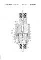
- a waterproof connector in accordance with the inventionhas a male housing part (A) and a female housing part (B) which are adapted to fit each other.
- the male housing part (A)has an inner sleeve 2 and an outer sleeve 3 which are fitted to each other.
- the inner sleeve 2has a chamber 4 for accommodating a male terminal 5 as shown in FIG. 3.
- An annular protrusion 6is formed on the same end of the inner sleeve as the direction of projection of the male terminal 5.
- Recesses 7, 7'are formed in the peripheral surface of the midportion of the inner sleeve 2 in such a manner as to diametrically oppose to each other.
- the inner sleeve 2 having the construction stated abovecan be formed by a split type mold having mold parts which are separable in the axial direction of the sleeve 2. Namely, it is possible to form the parting line of the mold parts on the peripheral surface of the annular protrusion 6, i.e., on a plane perpendicular to the axis of the annular protrusion 6.
- the outer sleeve 3is constituted of a small-diameter sleeve portion 8, having an inside diameter substantially equal to the outside diameter of the inner sleeve 2 and a thickness substantially equal to the projection length of the annular protrusion 6, and a large-diameter sleeve portion 11 connected to the peripheral wall of the midportion of the small-diameter sleeve 8 through an annular wall 9.
- the large-diameter sleeve portion 11extends at a distance from the outer peripheral surface of the small diameter portion 8 axially beyond one open end 10 of the small-diameter sleeve 8.
- the small-diameter sleeve portion 8has another open end 12 opposite to the first-mentioned end 10 as shown in FIG. 4.
- Slits 13, 13', 14, 14'are formed in the wall of the small-diameter sleeve portion 8 from the open end 12 to reach the base portion of the annular wall 9, thereby to leave cantilevered tabs 15, 15' which are spaced 180° from each other around the axis of the small-diameter sleeve portion 8.
- the free ends of these tabs 15, 15'are bent inwardly to form hooks 16, 16' as shown in FIG. 3.
- the large diameter sleeve portion 11has notches or grooves 17 extending from the annular wall 9 to the open end thereof along the tabs 15, 15'.
- An arm 19 having a fulcrum portion 18 extending between opposing surfaces of the groove 17is disposed in the groove 17.
- a hooked portion 20is formed on the end of the arm 19 adjacent to the open end of the large-diameter sleeve portion 11, while the other end of the same is narrowed and thinned toward the outside.
- Reference numerals 21, 21'designate side walls extending between the ends of the slits 13, 13' of the small-diameter sleeve portion 8 adjacent to the body of the latter to the end of the groove 17 of the large-diameter sleeve portion 11.
- the inner sleeve 2 and the outer sleeve 3are firmly anchored to each other with the hooks 16, 16' of the tabs 15, 15' of outer sleeve 3 engaged and received by the recesses 7, 7' of the inner sleeve 2 to prevent the outer sleeve 3 from being disengaged from the inner sleeve 2.
- an annular recess 22is formed between the open end 10 of the small-diameter portion 8 of the outer sleeve 3 and the annular protrusion 6 of the inner sleeve 2.
- An "O" ring made of an elastic member such as rubberis wound around and received by the annular recess 22.
- the female housing part Bhas a chamber 25 for accomodating a female terminal 24 of well-known type which includes a male terminal receptacle portion having a base plate and curved side walls each rising from one lateral end of the base plate and curved inwardly to have a free edge opposed with a small clearance to the upper surface of the base plate.
- An opening 26 for receiving the male housing Ais formed to communicate with this chamber 25.
- the opening 26is defined by a cylindrical wall 27 having an inside diameter substantially equal to the outside diameter of the annular protrusion 6 and an outside diameter substantially equal to the inside diameter of the large-diameter sleeve portion 11 of the outer sleeve 3.
- a recess 28is formed in the outer peripheral surface of the female housing part B.
- the male and female housing parts (A) and (B)To assemble the male and female housing parts (A) and (B), these housing parts are brought together so that the cylindrical wall 27 of the female housing part B is forced into the gap between the small-diameter sleeve portion 8 and the large-diameter sleeve portion 11 of the male housing part (A) beyond the annular recess 22 of the latter, while the hook 20 of the arm 19 formed in the male housing part (A) is received and retained by the recess 28 of the female housing part (B).
- the "O" ring 23 wound around the annular recess 22makes resilient contacts with the outer peripheral surface of the inner sleeve 2 and the inner peripheral surface of the cylindrical wall 27 of the female housing (B) to achieve an effective seal therebetween.
- reference numerals 29, 29'denote protrusions or ridges formed on the outer peripheral surface of the female housing part (B) at a 180° interval around the axis of the female housing part (B), while numerals 30, 30' denote guide openings cut from the open end edge of the outer sleeve 3 and adapted to restrict the positional relationship between the two housing parts (B), (A) in the rotational direction.
- a waterproof connectorconstituted by male and female housing parts A and B adapted to fit each other, wherein the male housing part A has the inner sleeve 2 around which is wound an "O" ring 23 and a large diameter sleeve portion 11 which is radially spaced from the inner sleeve 2, while the female housing part B has a cylindrical wall 27 adapted to fit in the gap between the large-diameter sleeve portion 11 and the inner sleeve 2, with the "O" ring pressed between the outer peripheral surface of the inner sleeve 2 and the inner peripheral surface of the cylindrical wall 27.
- the "O" ring 23is never exposed to the outside before the assembling of the male and female housing parts A and B, so that the "O” ring is protected from any external damaging force during the assembling of the wire harness, as well as during the mounting of the harness on the automobile, to ensure a good sealing effect of the "O" ring.
- the male housing part (A) of the waterproof connector of the inventionis formed of an inner sleeve 2 and an outer sleeve 3 which are shaped as separate bodies.
- the inner sleeve 2has an annular protrusion 6 formed on one open end thereof, while the outer sleeve 3 has a small-diameter sleeve portion 8 having an inside diameter substantially equal to the outside diameter of the inner sleeve 2 and a thickness substantially equal to the projection length of the annular protrusion 6, and a large-diameter sleeve portion 11 connected to the small-diameter sleeve portion 8 through an annular wall 9 and extending forwardly beyond the open end 10 of the small-diameter sleeve portion 8 at a predetermined radial distance from the latter.
- the annular recess 22 for receiving the "O" ring 23is formed between the annular protrusion 6 of the inner sleeve 2 and the open end 10 of the small-diameter sleeve portion 8 of the outer sleeve 3. Therefore, it is possible to avoid the formation of burrs in the surface of the annular recess 22, which burrs have been inevitably formed on the surface of the annular recess 22 in the conventional connector along the parting line of the split mold. The elimination of the axial burrs on the surface of the annular recess 22 ensures a close fit of the "O" ring 23 in the latter to provide an enhanced sealing effect over the conventional waterproof connector.
Landscapes
- Connector Housings Or Holding Contact Members (AREA)
Abstract
Description
Claims (1)
Applications Claiming Priority (2)
| Application Number | Priority Date | Filing Date | Title |
|---|---|---|---|
| JP1980071794UJPS6344952Y2 (en) | 1980-05-23 | 1980-05-23 | |
| JP55/71794[U] | 1980-05-23 |
Publications (1)
| Publication Number | Publication Date |
|---|---|
| US4395085Atrue US4395085A (en) | 1983-07-26 |
Family
ID=13470822
Family Applications (1)
| Application Number | Title | Priority Date | Filing Date |
|---|---|---|---|
| US06/265,689Expired - Fee RelatedUS4395085A (en) | 1980-05-23 | 1981-05-20 | Waterproof connector |
Country Status (4)
| Country | Link |
|---|---|
| US (1) | US4395085A (en) |
| JP (1) | JPS6344952Y2 (en) |
| AU (1) | AU541862B2 (en) |
| GB (1) | GB2077056B (en) |
Cited By (16)
| Publication number | Priority date | Publication date | Assignee | Title |
|---|---|---|---|---|
| US4486062A (en)* | 1981-11-30 | 1984-12-04 | Tokai Electric Wire Company, Ltd. | Waterproof connector |
| US4556226A (en)* | 1983-07-15 | 1985-12-03 | Tokai Electric Wire Company Limited | Water-proof connector |
| US4611872A (en)* | 1983-09-21 | 1986-09-16 | Tokai Electric Wire Company Limited | Water-proof connector |
| US4690478A (en)* | 1986-04-10 | 1987-09-01 | United Technologies Automotive, Inc. | Sealed electrical connector assembly |
| EP0214819A3 (en)* | 1985-08-30 | 1989-02-01 | Thomas & Betts Corporation | Raintight and oiltight connector for flexible conduit |
| EP0300804A3 (en)* | 1987-07-24 | 1990-04-11 | Honda Giken Kogyo Kabushiki Kaisha | Water-proof connector |
| US4940419A (en)* | 1988-03-25 | 1990-07-10 | Yazaki Corporation | Electrical junction box |
| US5083943A (en)* | 1989-11-16 | 1992-01-28 | Amphenol Corporation | Catv environmental f-connector |
| US5173053A (en)* | 1991-11-26 | 1992-12-22 | Caterpillar Inc. | Electrical connector for an electromechanical device |
| US5197899A (en)* | 1991-04-30 | 1993-03-30 | Yazaki Corporation | Water-proof connector |
| US5240431A (en)* | 1991-07-10 | 1993-08-31 | Yazaki Corporation | Waterproof connector |
| US5356304A (en)* | 1993-09-27 | 1994-10-18 | Molex Incorporated | Sealed connector |
| US5536103A (en)* | 1992-10-07 | 1996-07-16 | Sumitomo Wiring Systems, Ltd. | Connector having core and insert-molded terminal |
| US20110294327A1 (en)* | 2009-12-11 | 2011-12-01 | Aerovironment , Inc. | Waterproof electrical connector and system |
| CN102946023A (en)* | 2011-08-15 | 2013-02-27 | 苏州快可光伏电子股份有限公司 | Waterproof connector combination |
| DE102019125153B4 (en) | 2019-09-18 | 2022-02-17 | Seliger Gmbh | Plug-in coupling for a lamp and connection system for an outdoor lamp |
Families Citing this family (4)
| Publication number | Priority date | Publication date | Assignee | Title |
|---|---|---|---|---|
| GB2149589B (en)* | 1983-11-08 | 1988-06-02 | Davis & Son John | A connector for releasable connection of a first to a second apparatus |
| DE3708827C2 (en)* | 1987-03-18 | 1993-10-28 | Prakla Seismos Gmbh | Multipole plug |
| US4790767A (en)* | 1987-11-16 | 1988-12-13 | Prestolite Wire Corporation | Electrical connector for a distributorless ignition system |
| JPH06119948A (en)* | 1992-10-07 | 1994-04-28 | Sumitomo Wiring Syst Ltd | Connector |
Citations (3)
| Publication number | Priority date | Publication date | Assignee | Title |
|---|---|---|---|---|
| US2467911A (en)* | 1946-01-17 | 1949-04-19 | Reilly Claude | Pipe coupling |
| US4037902A (en)* | 1976-03-16 | 1977-07-26 | Tesco Engineering Company | Hermaphroditic multiple connector plug |
| US4304456A (en)* | 1979-12-10 | 1981-12-08 | The Bendix Corporation | Connector for small diameter elongated sonar arrays |
- 1980
- 1980-05-23JPJP1980071794Upatent/JPS6344952Y2/janot_activeExpired
- 1981
- 1981-05-20USUS06/265,689patent/US4395085A/ennot_activeExpired - Fee Related
- 1981-05-20AUAU70863/81Apatent/AU541862B2/ennot_activeCeased
- 1981-05-21GBGB8115649Apatent/GB2077056B/ennot_activeExpired
Patent Citations (3)
| Publication number | Priority date | Publication date | Assignee | Title |
|---|---|---|---|---|
| US2467911A (en)* | 1946-01-17 | 1949-04-19 | Reilly Claude | Pipe coupling |
| US4037902A (en)* | 1976-03-16 | 1977-07-26 | Tesco Engineering Company | Hermaphroditic multiple connector plug |
| US4304456A (en)* | 1979-12-10 | 1981-12-08 | The Bendix Corporation | Connector for small diameter elongated sonar arrays |
Cited By (18)
| Publication number | Priority date | Publication date | Assignee | Title |
|---|---|---|---|---|
| US4486062A (en)* | 1981-11-30 | 1984-12-04 | Tokai Electric Wire Company, Ltd. | Waterproof connector |
| US4556226A (en)* | 1983-07-15 | 1985-12-03 | Tokai Electric Wire Company Limited | Water-proof connector |
| US4611872A (en)* | 1983-09-21 | 1986-09-16 | Tokai Electric Wire Company Limited | Water-proof connector |
| EP0214819A3 (en)* | 1985-08-30 | 1989-02-01 | Thomas & Betts Corporation | Raintight and oiltight connector for flexible conduit |
| US4690478A (en)* | 1986-04-10 | 1987-09-01 | United Technologies Automotive, Inc. | Sealed electrical connector assembly |
| EP0300804A3 (en)* | 1987-07-24 | 1990-04-11 | Honda Giken Kogyo Kabushiki Kaisha | Water-proof connector |
| US4940419A (en)* | 1988-03-25 | 1990-07-10 | Yazaki Corporation | Electrical junction box |
| US5083943A (en)* | 1989-11-16 | 1992-01-28 | Amphenol Corporation | Catv environmental f-connector |
| US5197899A (en)* | 1991-04-30 | 1993-03-30 | Yazaki Corporation | Water-proof connector |
| US5240431A (en)* | 1991-07-10 | 1993-08-31 | Yazaki Corporation | Waterproof connector |
| US5173053A (en)* | 1991-11-26 | 1992-12-22 | Caterpillar Inc. | Electrical connector for an electromechanical device |
| US5536103A (en)* | 1992-10-07 | 1996-07-16 | Sumitomo Wiring Systems, Ltd. | Connector having core and insert-molded terminal |
| US5356304A (en)* | 1993-09-27 | 1994-10-18 | Molex Incorporated | Sealed connector |
| US20110294327A1 (en)* | 2009-12-11 | 2011-12-01 | Aerovironment , Inc. | Waterproof electrical connector and system |
| US8257113B2 (en)* | 2009-12-11 | 2012-09-04 | Aerovironment, Inc. | Waterproof electrical connector and system |
| US8491336B2 (en)* | 2009-12-11 | 2013-07-23 | Aerovironment, Inc. | Waterproof electrical connector and system |
| CN102946023A (en)* | 2011-08-15 | 2013-02-27 | 苏州快可光伏电子股份有限公司 | Waterproof connector combination |
| DE102019125153B4 (en) | 2019-09-18 | 2022-02-17 | Seliger Gmbh | Plug-in coupling for a lamp and connection system for an outdoor lamp |
Also Published As
| Publication number | Publication date |
|---|---|
| AU541862B2 (en) | 1985-01-24 |
| GB2077056A (en) | 1981-12-09 |
| AU7086381A (en) | 1981-11-26 |
| JPS56172271U (en) | 1981-12-19 |
| JPS6344952Y2 (en) | 1988-11-22 |
| GB2077056B (en) | 1984-08-08 |
Similar Documents
| Publication | Publication Date | Title |
|---|---|---|
| US4395085A (en) | Waterproof connector | |
| EP0677894B1 (en) | Sealing device and method for producing a waterproof connector | |
| CN111133648B (en) | Cable seal and device with housing | |
| US5618206A (en) | Waterproof connector having a connector housing with a plurality of terminal accommodation chambers and a seal hood | |
| US5252088A (en) | Sealed pass through electrical connector | |
| EP1150393B1 (en) | Connector | |
| JPH07263076A (en) | Waterproof structure of connector | |
| EP2400600A1 (en) | Waterproof connector | |
| US4486062A (en) | Waterproof connector | |
| US20190067869A1 (en) | Rubber plug and waterproof connector | |
| JP7082155B2 (en) | Connector with cap | |
| KR20090116771A (en) | Sealable electrical connectors | |
| EP0585562B1 (en) | Connector | |
| US20210249810A1 (en) | Connector | |
| JP7488012B2 (en) | connector | |
| JPH1186836A (en) | Battery fittings | |
| JP3335733B2 (en) | Waterproof connector | |
| JPH0249657Y2 (en) | ||
| JP7601738B2 (en) | Connector part having attachment structure for separate member | |
| JP7601739B2 (en) | Connector with a connector member having four terminals | |
| JP2552277Y2 (en) | Grommet | |
| JPH0238384Y2 (en) | ||
| JPS6234019Y2 (en) | ||
| JPH0429511Y2 (en) | ||
| JP3224354B2 (en) | Mounting structure of pressure switch |
Legal Events
| Date | Code | Title | Description |
|---|---|---|---|
| AS | Assignment | Owner name:TOKAI ELECTRIC WIRE COMPANY LIMITED, 1-14, NISHISU Free format text:ASSIGNMENT OF ASSIGNORS INTEREST.;ASSIGNOR:INOUE, NORI;REEL/FRAME:003890/0139 Effective date:19810511 | |
| MAFP | Maintenance fee payment | Free format text:PAYMENT OF MAINTENANCE FEE, 4TH YEAR, PL 96-517 (ORIGINAL EVENT CODE: M170); ENTITY STATUS OF PATENT OWNER: LARGE ENTITY Year of fee payment:4 | |
| AS | Assignment | Owner name:SUMITOMO WIRING SYSTEMS, LTD. Free format text:CHANGE OF NAME;ASSIGNOR:TOKAI ELECTRIC WIRE COMPANY LIMITED;REEL/FRAME:004764/0295 Effective date:19870826 | |
| MAFP | Maintenance fee payment | Free format text:PAYMENT OF MAINTENANCE FEE, 8TH YEAR, PL 96-517 (ORIGINAL EVENT CODE: M171); ENTITY STATUS OF PATENT OWNER: LARGE ENTITY Year of fee payment:8 | |
| FEPP | Fee payment procedure | Free format text:PAYOR NUMBER ASSIGNED (ORIGINAL EVENT CODE: ASPN); ENTITY STATUS OF PATENT OWNER: LARGE ENTITY | |
| FEPP | Fee payment procedure | Free format text:PAYOR NUMBER ASSIGNED (ORIGINAL EVENT CODE: ASPN); ENTITY STATUS OF PATENT OWNER: LARGE ENTITY Free format text:PAYER NUMBER DE-ASSIGNED (ORIGINAL EVENT CODE: RMPN); ENTITY STATUS OF PATENT OWNER: LARGE ENTITY | |
| FEPP | Fee payment procedure | Free format text:MAINTENANCE FEE REMINDER MAILED (ORIGINAL EVENT CODE: REM.); ENTITY STATUS OF PATENT OWNER: LARGE ENTITY | |
| LAPS | Lapse for failure to pay maintenance fees | ||
| FP | Lapsed due to failure to pay maintenance fee | Effective date:19950726 | |
| STCH | Information on status: patent discontinuation | Free format text:PATENT EXPIRED DUE TO NONPAYMENT OF MAINTENANCE FEES UNDER 37 CFR 1.362 |