US4394966A - Spraying apparatus having a fluid storage tank with agitator and anti-vortex tank fittings - Google Patents
Spraying apparatus having a fluid storage tank with agitator and anti-vortex tank fittingsDownload PDFInfo
- Publication number
- US4394966A US4394966AUS05/904,274US90427478AUS4394966AUS 4394966 AUS4394966 AUS 4394966AUS 90427478 AUS90427478 AUS 90427478AUS 4394966 AUS4394966 AUS 4394966A
- Authority
- US
- United States
- Prior art keywords
- fluid
- storage tank
- fluid storage
- agitator
- vortex
- Prior art date
- Legal status (The legal status is an assumption and is not a legal conclusion. Google has not performed a legal analysis and makes no representation as to the accuracy of the status listed.)
- Expired - Lifetime
Links
Images


Classifications
- B—PERFORMING OPERATIONS; TRANSPORTING
- B05—SPRAYING OR ATOMISING IN GENERAL; APPLYING FLUENT MATERIALS TO SURFACES, IN GENERAL
- B05B—SPRAYING APPARATUS; ATOMISING APPARATUS; NOZZLES
- B05B15/00—Details of spraying plant or spraying apparatus not otherwise provided for; Accessories
- B—PERFORMING OPERATIONS; TRANSPORTING
- B01—PHYSICAL OR CHEMICAL PROCESSES OR APPARATUS IN GENERAL
- B01F—MIXING, e.g. DISSOLVING, EMULSIFYING OR DISPERSING
- B01F25/00—Flow mixers; Mixers for falling materials, e.g. solid particles
- B01F25/20—Jet mixers, i.e. mixers using high-speed fluid streams
- B01F25/21—Jet mixers, i.e. mixers using high-speed fluid streams with submerged injectors, e.g. nozzles, for injecting high-pressure jets into a large volume or into mixing chambers
- B01F25/211—Jet mixers, i.e. mixers using high-speed fluid streams with submerged injectors, e.g. nozzles, for injecting high-pressure jets into a large volume or into mixing chambers the injectors being surrounded by guiding tubes
- B—PERFORMING OPERATIONS; TRANSPORTING
- B01—PHYSICAL OR CHEMICAL PROCESSES OR APPARATUS IN GENERAL
- B01F—MIXING, e.g. DISSOLVING, EMULSIFYING OR DISPERSING
- B01F25/00—Flow mixers; Mixers for falling materials, e.g. solid particles
- B01F25/50—Circulation mixers, e.g. wherein at least part of the mixture is discharged from and reintroduced into a receptacle
- B—PERFORMING OPERATIONS; TRANSPORTING
- B05—SPRAYING OR ATOMISING IN GENERAL; APPLYING FLUENT MATERIALS TO SURFACES, IN GENERAL
- B05B—SPRAYING APPARATUS; ATOMISING APPARATUS; NOZZLES
- B05B15/00—Details of spraying plant or spraying apparatus not otherwise provided for; Accessories
- B05B15/20—Arrangements for agitating the material to be sprayed, e.g. for stirring, mixing or homogenising
- B—PERFORMING OPERATIONS; TRANSPORTING
- B05—SPRAYING OR ATOMISING IN GENERAL; APPLYING FLUENT MATERIALS TO SURFACES, IN GENERAL
- B05B—SPRAYING APPARATUS; ATOMISING APPARATUS; NOZZLES
- B05B9/00—Spraying apparatus for discharge of liquids or other fluent material, without essentially mixing with gas or vapour
- B05B9/03—Spraying apparatus for discharge of liquids or other fluent material, without essentially mixing with gas or vapour characterised by means for supplying liquid or other fluent material
- B05B9/04—Spraying apparatus for discharge of liquids or other fluent material, without essentially mixing with gas or vapour characterised by means for supplying liquid or other fluent material with pressurised or compressible container; with pump
- B05B9/0403—Spraying apparatus for discharge of liquids or other fluent material, without essentially mixing with gas or vapour characterised by means for supplying liquid or other fluent material with pressurised or compressible container; with pump with pumps for liquids or other fluent material
Definitions
- the present inventionis directed to spraying apparatus which includes a fluid storage tank having an agitator for mixing the fluid in the fluid storage tank and an anti-vortex device for preventing the formation of a gyrating vortex in the fluid as the fluid is discharged from the fluid storage tank.
- Emulsifiable or wettable powdersare frequently employed as active ingredients for a variety of applications, including agricultural herbicides, insecticides or fungicides, as well as other industrial uses.
- these emulsifiable or wettable powdersare mixed in water solutions or mixed with liquid fertilizer, the solid particles tend to settle and collect at the bottom of the fluid storage tank since these particles are normally only held in suspension rather than being dissolved in the solution.
- spraying apparatus of this typegenerally includes a fluid storage tank which is connected to a pump for pumping the fluid stored in the fluid storage tank to spray heads or nozzles. Normally, agitation of the fluid in the fluid storage tank is accomplished by returning a portion of the solution from the pump back to the fluid storage tank viz a bypass pipe. The momentum of the fluid in the bypass pipe agitates the fluid in the fluid storage tank.
- a spraying apparatusis shown in U.S. Pat. No. 2,692,798 issued to Hicks on Oct. 26, 1954. In this patent, the bypass pipe protrudes into the fluid storage tank and a biased agitator cap is responsive to the pressure of the fluid in the bypass pipe to permit the bypass fluid to flow into the fluid storage tank to thereby mix the fluid contained therein.
- Venturi mixer nozzleshave been connected on the end of the bypass pipe near the bottom of the fluid storage tank to draw the settling or precipitating particles and the surrounding liquid into the Venturi mixer nozzle whereupon it is discharged with force sufficient to agitate the fluid in the fluid storage tank.
- Agitator devices which employ Venturi mixer nozzlesare shown in U.S. Pat. No. 3,826,474 issued to Pareja on July 30, 1974 and French Pat. No. 1,142,557 published on Sept. 19, 1957.
- Other types of nozzleshave been employed in the prior art for improving the agitation of the fluid in the fluid storage tank.
- a pressure nozzleis located near the bottom of the fluid storage tank in order to subject the fluid in the fluid storage tank to a rotationally symmetrical circulatory movement as the fluid in the bypass pipe impinges against the bottom of the tank.
- Another technique employed in the prior art for mixing the fluid in a fluid storage tankis a sparging system in which agitation of the fluid is achieved by introducing compressed air into the fluid.
- compressed airis forced from an inlet pipe through spiral channels near the bottom of the fluid storage tank to thereby mix the fluid in a spiral rotating fashion.
- U.S. Pat. No. 3,276,698 issued to Wood on Oct. 4, 1966shows a system in which compressed air is introduced into the fluid through a protruding pipe having a movable closure cap responsive to the pressure of the compressed air.
- the closure capoverlays the opening of the protruding pipe when no air is fed to the agitator. Under air pressure, the closure cap rises to create an annular opening through which the compressed air passes into the fluid in the fluid storage tank.
- the underside of the closure capincludes a plurality of spiral ribs which impart a spiral rotating motion to the compressed air as it passes through the annular opening.
- the pump in prior art spraying apparatushas a tendency to cavitate or suck in air as the fluid is withdrawn from the fluid storage tank.
- a gyrating vortexto be generated in the fluid as it enters the fluid outlet pipe. Cavitation of the pump is caused by creating excessive low pressure at the suction side of the pump which either vaporizes the fluid or causes such a quantity of the fluid to move into the pump that a gyrating vortex is generated within the fluid.
- This gyrating vortex or hollow corepermits air to enter the pump and causes the pump to lose prime and invariably causes a loss of pump efficiency. As a result, rapid wear on the pump impeller occurs.
- an agitator for a spraying apparatusin which agitation is accomplished over a wide range of pressures and flow rates by imparting a gentle rolling motion to the fluid in the fluid storage tank. It is an object of the present invention to provide an agitator in which mixing down to as low as two pounds per square inch and five gallons per minute and up to ten pounds per square inch and fifty gallons a minute can be achieved. These values fall within the normal range of bypass pump systems presently used in the agricultural industry.
- the inventionis directed to spraying apparatus for spraying a fluid stored in a fluid storage tank.
- the spraying apparatusincludes a pump connected to the fluid storage tank by a fluid outlet pipe and spray heads connected to the pump by a spray pipe.
- the spray headsspray the fluid pumped from the fluid storage tank.
- a bypass return pipeis also connected between the spray pipe and the fluid storage tank for returning a portion of the fluid to the fluid storage tank.
- the present inventionis directed to an agitator connected to the bypass return pipe for mixing the fluid in the fluid storage tank and an anti-vortex device connected to the fluid outlet pipe for preventing the formation of a gyrating vortex in the fluid in the fluid storage tank.
- the agitatormixes the fluid in the fluid storage tank by transferring the momentum of the fluid in the bypass return pipe to the fluid in the fluid storage tank.
- the agitatorincludes a conical plate having its concave side overlaying the opening in the bypass return pipe at a fixed distance therefrom. Spiral shaped ribs or fins are mounted on the concave side of the conical plate for imparting a spiral rotating motion of the fluid discharged by the bypass return pipe.
- the shape of the conical plateprovides a focusing or directing effect on the fluid discharged by the bypass return pipe which in turn allows the spiral shaped ribs or fins to be considerably more effective in distributing the fluid.
- the agitatorfurther includes a nozzle coupled between the opening in the bypass return pipe and the conical plate.
- This nozzleextends substantially along the center line of the conical plate for defining a fixed gap between the conical plate and the nozzle.
- the fixed gap formed by the nozzlecontrols the pressure drop across the conical plate and the nozzle to thereby control the momentum of the fluid in the fluid storage tank.
- the nozzledirects the fluid from the bypass return pipe to the center of the conical plate to help provide an even distribution of the fluid from the bypass return pipe.
- the fluid from the bypass return pipeis discharged in the fluid storage tank in a spiral rotating fashion to thereby mix the fluid in the fluid storage tank by imparting a gentle rolling motion thereto.
- the fixed gap defined by the nozzlemay be smaller than the height of the spiral shaped fins near the center of the conical plate in order to improve the spiral shaped motion of the fluid in the fluid storage tank.
- the nozzlemay be modified to change the length of the fixed gap in order to vary the pressure drop across the gap.
- the anti-vortex device of the present inventionis mounted on the bottom wall of the fluid storage tank and is connected to the fluid outlet pipe.
- the anti-vortex deviceprevents the formation of a gyrating vortex in the fluid as it leaves the fluid storage tank.
- a capoverlays the opening in the fluid outlet pipe at a fixed distance therefrom for forcing the fluid in the fluid storage tank to make a substantially 90 degree turn in order to leave through the fluid outlet pipe.
- the capextends beyond, and is positioned slightly above, the opening in the fluid outlet pipe.
- the agitator and the anti-vortex deviceare made of similar elements which are removable.
- the conical plate and the nozzle of the agitatormay be removed from the tank fitting which attaches the agitator to the bypass return pipe.
- the cap of the anti-vortex devicemay be the same as the conical plate in the agitator, the agitator can be converted into an anti-vortex device simply by removing the nozzle.
- the primary structural difference between the agitator and the anti-vortex deviceis the use of a nozzle in the agitator to control the fluid momentum in the fluid storage tank.
- the similarity of these elementsgreatly simplifies the manufacturing process which in turn lowers the overall cost.
- FIG. 1is a side view of an agitator according to the present invention which is mounted on a fluid storage tank.
- FIG. 2shows the spraying apparatus of the present invention including a cross sectional view of the agitator and the anti-vortex device taken along lines 2--2 of FIG. 1.
- FIG. 3shows a cross sectional view of the anti-vortex device taken along lines 3--3 of FIG. 2.
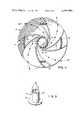
- FIG. 4shows a cross sectional view of the underside of the conical cap of the agitator taken along lines 4--4 of FIG. 2.
- FIG. 5is a perspective view of the injector nozzle of the agitator of FIGS. 1 and 2.
- FIG. 2which includes a cross sectional view of the agitator 10 and the anti-vortex device 12 mounted on fluid storage tank 14.
- the anti-vortex device 12is connected to a pump 16 by a fluid outlet pipe 18.
- the pump 16forces the fluid from the fluid storage tank 14 to one or more spray heads or nozzles which are connected to the pump 16 by spray pipe 20 and valve 22.
- spray headsare not shown in the drawings, any one of a number of known spray heads may be used in the present invention.
- a bypass return pipe 24is also connected to the outlet of the pump 16 via a tee 26 which is connected to the spray pipe 20.
- a portion of the fluid pumped by the pump 16is returned to the fluid storage tank 14 for the purpose of agitating the fluid in the fluid storage tank 14.
- the use of a bypass return pipe 24 in this manneris generally known in the art.
- the bypass return pipe or fluid inlet pipe 24, which includes a valve 27,is connected to the agitator 10 in the fluid storage tank 14.
- the agitator 10is mounted on one of the walls of the fluid storage tank 14 by a tank fitting 28 and nut 30.
- a gasket 32is also provided for sealing the inside wall of the fluid storage tank 14.
- the tank fitting 28includes a threaded opening for engaging the bypass return pipe 24.
- the agitator 10performs less efficiently when connected in this alternative manner than when mounted on the wall of the fluid storage tank 14.
- the agitator 10is shown in FIGS. 1 and 2 in a vertical position on the bottom wall of the fluid storage tank 14, it should be appreciated that the agitator 10 may be mounted in other positions although it generally performs most efficiently when mounted as shown.
- the agitator 10includes a conical cap 34 which is mounted on the tank fitting 28 by a plurality of support bars 36 and 38.
- FIG. 3shows a cross sectional view of the anti-vortex device 12
- the conical cap 34 of the agitator 10is coupled to the tank fitting 28 in the same manner.
- the support bars 36include notches 40 for engaging tabs 42 on the tank fitting 28.
- the support bars 38abutt another pair of tabs 42 on the tank fitting 28. Since the conical cap 34 may be formed of flexible plastic, the conical cap 34 may be removed from the tank fitting 28 by disconnecting the support bars 36 from the tabs 42 of the tank fitting 28.
- the agitator 10also includes an injector nozzle 44 which is mounted between the tank fitting 28 and the conical cap 34.
- the injector nozzle 44directs the fluid from the bypass return pipe 24 to a location near the center or vortex of the conical cap 34.
- the concave surface of the conical cap 34provides a focus for the fluid from the injector nozzle 44. Because of the shape of the conical cap 34, the fluid from the injector nozzle 44 is evenly distributed about the agitator 10 in the fluid storage tank 14.
- the agitator 10is mounted on the bottom wall of the fluid storage tank 14 because solid particles which settle out of the fluid will be located on the bottom wall of the fluid storage tank 14.
- the conical cap 34By providing a focus for the fluid in the bypass return pipe 24 and directing the fluid in a downward direction toward the bottom wall of the fluid storage tank 14, the conical cap 34 enables the agitator 10 to thorougly mix those particles which settle out of the fluid in the fluid storage tank 14.
- the conical cap 34also naturally sheds sediment under the slightest movement of the fluid in the fluid storage tank 14 thereby preventing a loss of entrained material.
- the injector nozzle 44is illustrated in further detail in FIG. 5.
- the injector nozzle 44includes an annular flange 46 which is supported by the tank fitting 28.
- An open cylinder 48is attached to the flange 46 for directing the fluid in the bypass return pipe 24 toward the conical cap 34.
- a plurality of nozzle pins 50extend between the cylinder 48 and the conical cap 34 for defining a fixed gap between the nozzle 44 and the conical cap 34. By defining the fixed gap, these spacer pins 50 determine the pressure drop across the nozzle 44 and the conical cap 34 which in turn controls the flow momentum in the fluid storage tank 14.
- the fixed gapmay be adjusted to allow the pressure drop across the bypass return pipe 24 to be insignificant compared to the pressure drop across the fixed gap.
- the fixed gapcan be adjusted by shortening the spacer pins 50 and adding a spacer ring between the flange 46 of the nozzle 44 and the tank fitting 28 to compensate for the adjustment in the length of the spacer pins 50.
- the spacer pins 50may be trimmed to increase the pressure drop across the fixed gap.
- the nozzle 44 of the present inventioncan be adjusted in size to ensure maximum momentum transfer across the fixed gap.
- the injector nozzle 44need not be rigidly fastened to the tank fitting 28 or the conical cap 34 because of the use of spacer pins 50, it should be appreciated that the spacer pins 50 can be eliminated by rigidly fastening the injector nozzle 44 to the tank fitting 28 and varying the length of the nozzle cylinder 48 in order to achieve different fixed gaps.
- the concave side of the conical cap 34is shown in further detail in FIG. 4.
- the conical capincludes a plurality of spiral ribs or fins 52. These spiral fins 52 extend from near the center to the rim of the conical cap 34. The purpose of these spiral fins 52 is to disperse the fluid from the bypass return pipe 24 in a spiral rotating fashion.
- the support bars 36 and 38are enclosed by the spiral fins 52 so that they do not interfere with the flow of the fluid across the concave side of the conical cap 34.
- the spiral rotating motion of the fluid moving across the concave side of the cap 34imparts a gentle rolling motion to the fluid in the fluid storage tank 14 which thoroughly mixes the fluid.
- the conical cap 34includes a deflecting cone 54 positioned at the center of the conical cap 34.
- the deflecting cone 54deflects the fluid as it leaves the injector nozzle 44 to the concave surface of the conical cap 34. In this manner, the deflecting cone 54 ensures that the fluid is evenly distributed over the plurality of spiral fins 52 which in turn enhances the mixing of the fluid in the fluid storage tank 14.
- the operation of the agitator 10 of the present inventionis apparent from the above discussion.
- the agitator 10transfers the momentum of the fluid in the bypass return pipe 24 and directs it in a proper manner to the fluid within the fluid storage tank 14 whereby thorough mixing of the fluid is accomplished.
- the fluid in the bypass return pipe 24passes through an injector nozzle 44 in agitator 10 in an upward manner and then is diverted by a conical cap 34 which provides a focus for the bypass fluid.
- the conical capthereby enhances the even distribution of the fluid across the spiral fins 52.
- the momentum of the spinning bypass fluidis transferred to the fluid in the fluid storage tank 14 thereby giving a gentle rolling motion to the tank fluid.
- the maximum effectiveness of the agitator 10occurs when it is positioned close to the bottom wall of the fluid storage tank 14 in order for the reflective flow from the conical cap 34 to cause the fluid momentum to be more efficiently used.
- the positioning of the agitator 10 on the bottom wall of the fluid storage tank 14takes advantage of the fact that the solid particles generally settle on the bottom of the fluid storage tank 14 due to gravity.
- the agitator 10will work in any position on the fluid storage tank 14 and further will work on a protruding bypass return pipe 24, the maximum effectiveness of the agitator 10 occurs on the bottom wall of the fluid storage tank 14.
- the agitator 10 of the present inventionis a liquid-to-liquid device which transfers the momentum of the bypass fluid to the fluid in the fluid storage tank 14.
- the anit-vortex device 12is similar in construction to the agitator 10 except that the injector nozzle 44 of the agitator 10 has been removed.
- the anti-vortex device 12is mounted on the bottom wall of the fluid storage tank 14 by a tank fitting 56 which is similar in construction to tank fitting 28 of the agitator 10 except that the threaded opening of the tank fitting 56 is larger.
- the tank fitting 56is mounted on the bottom wall of the fluid storage tank 14 by nut 30.
- a gasket 32seals the inside wall of the fluid storage tank 14.
- An anti-vortex cap 58is mounted on the tank fitting 56 by support bars 36 and 38 in the same manner as conical cap 34 is mounted to tank fitting 28 in agitator 10.
- the anti-vortex cap 58is similar in construction to the conical cap 34 of the agitator 10 as shown in FIG. 2, this conical shape of the anti-vortex cap 58 has no major significance in the anti-vortex device 12. The primary reason for the similarity between these caps is for ease and simplicity of manufacturing. Likewise, the spiral fins 52 on the anti-vortex cap 58 do not perform any function. The only function of the conical shape of the anti-vortex cap 58 is to shed sediment which settles out of the fluid in the fluid storage tank 14.
- the anti-vortex cap 58can be removed from the tank fitting 56 to facilitate the repair of the anti-vortex device 12 as well as to enable the user of either the agitator 10 or the anti-vortex device 12 to convert from one device to another by removing the injector nozzle 44.
- the anti-vortex device 12must be in a vertical position on the bottom wall of the fluid storage tank 14 in order to perform properly.
- the anti-vortex device 12is connected to the fluid outlet pipe 18 which carries fluid from the fluid storage tank 14 to the pump 16.
- the purpose of the anti-vortex device 12is to prevent the formation of a gyrating vortex in the fluid in the fluid storage tank 14.
- the low pressure at the suction side of the pump 16would cause such a quantity of the fluid to move into the pump 16 as to cause a gyrating vortex or hollow core to be formed in the fluid at the inlet of the fluid outlet pipe 18.
- the formation of a gyrating vortexwould allow air to enter the pump 16 which would cause the pump to lose prime and invariably cause a loss of pump efficiency.
- the anti-vortex device 12 of the present inventionforces any gyrating vortex in the fluid to make a substantially 90 degree turn in order to enter the inlet of the fluid outlet pipe 18. Since the vectorial momentum forces in the fluid will not permit the fluid to make a substantially 90 degree turn, any gyrating vortex becomes self-destructive.
- the operation of a gyroscopeis somewhat analogous to the operation of the anti-vortex device 12. If one were to try to change the direction of a spinning gyroscope, the gyroscope would resist this change in direction due to the vectorial momentum forces stored in the spinning gyroscope.
- the anti-vortex device 12 of the present inventionimproves the efficiency and life of the pump 16 by preventing the formation of a gyrating vortex.
Landscapes
- Chemical & Material Sciences (AREA)
- Chemical Kinetics & Catalysis (AREA)
- Catching Or Destruction (AREA)
Abstract
Description
Claims (25)
Priority Applications (1)
| Application Number | Priority Date | Filing Date | Title |
|---|---|---|---|
| US05/904,274US4394966A (en) | 1978-05-09 | 1978-05-09 | Spraying apparatus having a fluid storage tank with agitator and anti-vortex tank fittings |
Applications Claiming Priority (1)
| Application Number | Priority Date | Filing Date | Title |
|---|---|---|---|
| US05/904,274US4394966A (en) | 1978-05-09 | 1978-05-09 | Spraying apparatus having a fluid storage tank with agitator and anti-vortex tank fittings |
Publications (1)
| Publication Number | Publication Date |
|---|---|
| US4394966Atrue US4394966A (en) | 1983-07-26 |
Family
ID=25418866
Family Applications (1)
| Application Number | Title | Priority Date | Filing Date |
|---|---|---|---|
| US05/904,274Expired - LifetimeUS4394966A (en) | 1978-05-09 | 1978-05-09 | Spraying apparatus having a fluid storage tank with agitator and anti-vortex tank fittings |
Country Status (1)
| Country | Link |
|---|---|
| US (1) | US4394966A (en) |
Cited By (64)
| Publication number | Priority date | Publication date | Assignee | Title |
|---|---|---|---|---|
| US4483486A (en)* | 1981-09-11 | 1984-11-20 | Lawn Doctor, Inc. | Method and apparatus for treating lawns with both granular and liquid treatment materials |
| US5022936A (en)* | 1988-12-07 | 1991-06-11 | Hitachi, Ltd. | Method for improving property of weld of austenitic stainless steel |
| US5121857A (en)* | 1988-07-16 | 1992-06-16 | Corrugated Products Limited | Agitating and dispensing arrangement for bag-in-box containers |
| US5323923A (en)* | 1992-08-17 | 1994-06-28 | Schauer Charles D | Waste container |
| US5899560A (en)* | 1998-02-20 | 1999-05-04 | Alstor Canada Inc. | Liquid slurry agitation apparatus |
| EP0963943A1 (en)* | 1998-06-08 | 1999-12-15 | INDAG Gesellschaft für Industriebedarf mbH | Process for agitating beverage basic constituents |
| WO2002011871A3 (en)* | 2000-08-09 | 2002-06-13 | Kinetics Chempure Systems Inc | Whirlpool reduction cap |
| US6616322B1 (en)* | 1999-09-07 | 2003-09-09 | Eric George Evans | Mixing apparatus |
| US6748972B2 (en)* | 2000-05-29 | 2004-06-15 | Renesas Technology Corp. | Water tank, cooling tower including the same and method of manufacturing semiconductor device |
| US20050129595A1 (en)* | 2002-08-22 | 2005-06-16 | Thomas Kao | Liquid recycle inlet distributor for reaction vessel used in hydroconversion of fossil fuels |
| US20060016591A1 (en)* | 2004-06-18 | 2006-01-26 | Brennon Cote | Apparatus and method for agitating reservoir while pumping |
| US20060186117A1 (en)* | 2005-02-24 | 2006-08-24 | Powertex, Inc. | Discharge apparatus for a shipping container |
| US20070071590A1 (en)* | 2005-09-21 | 2007-03-29 | Podd Stephen D | Spillbox system for a shipping container |
| US20070145194A1 (en)* | 2005-12-22 | 2007-06-28 | Behruzi Kei P | Fuel tank with specialized tank outlet for spacecraft |
| US20070193649A1 (en)* | 2006-02-17 | 2007-08-23 | Podd Stephen D | Pressure differential manlid and method of discharging a shipping container using a pressure differential |
| US20070289298A1 (en)* | 2006-06-15 | 2007-12-20 | Thompson Dennis G | Suspension arrangement for a boom assembly mounted on an agricultural sprayer |
| US20080146679A1 (en)* | 2006-10-25 | 2008-06-19 | Revalesio Corporation | Methods of therapeutic treatment of eyes and other human tissues using an oxygen-enriched solution |
| US20080237099A1 (en)* | 2007-02-03 | 2008-10-02 | Kei Philipp Behruzi | Tank with a gas extraction device for storing cryogenic liquid or fuel for spacecraft |
| US20080257893A1 (en)* | 2007-04-19 | 2008-10-23 | Podd Stephen D | Bulk liquid transport system |
| US20080257894A1 (en)* | 2007-04-19 | 2008-10-23 | Podd Stephen D | Bulk liquid transport system |
| US7506776B2 (en) | 2005-02-10 | 2009-03-24 | Powertex, Inc. | Braceless liner |
| US20090134170A1 (en)* | 2005-09-17 | 2009-05-28 | Kei Philipp Behruzi | Propellant Tank for Cryogenic Liquids |
| US20090145514A1 (en)* | 2007-12-11 | 2009-06-11 | Sisk David E | Aerator device inducing cyclonic flow |
| US20090166449A1 (en)* | 2007-12-28 | 2009-07-02 | Chemilizer Products, Inc. | Apparatus for mixing chemicals with a liquid carrier |
| US20090293729A1 (en)* | 2008-06-03 | 2009-12-03 | Astrium Gmbh | Tank with a gas supply and extraction device for storing cryogenic liquid or fuel for spacecraft |
| US20100004189A1 (en)* | 2007-10-25 | 2010-01-07 | Revalesio Corporation | Compositions and methods for treating cystic fibrosis |
| US20100008180A1 (en)* | 2006-07-03 | 2010-01-14 | Soren Friis Krogh | Apparatus for dissolving solid particles and liquid substances in a liquid |
| US20100012666A1 (en)* | 2008-05-30 | 2010-01-21 | Millipore Corporation | Container having vortex breaker and system |
| US7654728B2 (en) | 1997-10-24 | 2010-02-02 | Revalesio Corporation | System and method for therapeutic application of dissolved oxygen |
| US20100065584A1 (en)* | 2008-09-17 | 2010-03-18 | Harvey Elliott Berger | Inline Fluid Dispenser |
| US20100077740A1 (en)* | 2008-09-30 | 2010-04-01 | Gm Global Technology Operations, Inc. | Exhaust gas aftertreatment system |
| US7770814B2 (en) | 1997-10-24 | 2010-08-10 | Revalesio Corporation | System and method for irrigating with aerated water |
| US7806584B2 (en) | 1997-10-24 | 2010-10-05 | Revalesio Corporation | Diffuser/emulsifier |
| US7832920B2 (en) | 2006-10-25 | 2010-11-16 | Revalesio Corporation | Mixing device for creating an output mixture by mixing a first material and a second material |
| US20100310665A1 (en)* | 2007-10-25 | 2010-12-09 | Revalesio Corporation | Bacteriostatic or bacteriocidal compositions and methods |
| US7887698B2 (en) | 1997-10-24 | 2011-02-15 | Revalesio Corporation | Diffuser/emulsifier for aquaculture applications |
| CN101981174A (en)* | 2008-03-26 | 2011-02-23 | 恩巴西斯有限责任公司 | Method for producing biogas |
| WO2011115618A1 (en)* | 2010-03-16 | 2011-09-22 | Harvey Elliott Berger | Inline fluid dispenser |
| CN102287403A (en)* | 2011-08-18 | 2011-12-21 | 兖矿国泰乙酰化工有限公司 | Vortex-resisting isolation hood for magnetic pump |
| US20120080112A1 (en)* | 2010-10-01 | 2012-04-05 | Amtrol Licensing Inc. | Device for causing turbulent flow in a tank assembly |
| WO2012045011A2 (en) | 2010-10-01 | 2012-04-05 | Amtrol Licensing Inc. | Devices and methods for causing turbulent flow in a tank assembly |
| US8397751B1 (en) | 2010-04-15 | 2013-03-19 | Wd Media, Inc. | Vortex reducer |
| US8445546B2 (en) | 2006-10-25 | 2013-05-21 | Revalesio Corporation | Electrokinetically-altered fluids comprising charge-stabilized gas-containing nanostructures |
| JP2013132641A (en)* | 2011-12-22 | 2013-07-08 | Mega Fluid Systems Inc | Vortex reduction cap |
| US20130201786A1 (en)* | 2011-04-11 | 2013-08-08 | Israel Harry Zimmerman | Energy-Saving Static Stirring Apparatus For Automatically Stirring A Fluid |
| US8609148B2 (en) | 2006-10-25 | 2013-12-17 | Revalesio Corporation | Methods of therapeutic treatment of eyes |
| US8617616B2 (en) | 2006-10-25 | 2013-12-31 | Revalesio Corporation | Methods of wound care and treatment |
| US8784898B2 (en) | 2006-10-25 | 2014-07-22 | Revalesio Corporation | Methods of wound care and treatment |
| US8784897B2 (en) | 2006-10-25 | 2014-07-22 | Revalesio Corporation | Methods of therapeutic treatment of eyes |
| US8815292B2 (en) | 2009-04-27 | 2014-08-26 | Revalesio Corporation | Compositions and methods for treating insulin resistance and diabetes mellitus |
| US8980325B2 (en) | 2008-05-01 | 2015-03-17 | Revalesio Corporation | Compositions and methods for treating digestive disorders |
| US9198929B2 (en) | 2010-05-07 | 2015-12-01 | Revalesio Corporation | Compositions and methods for enhancing physiological performance and recovery time |
| US9492404B2 (en) | 2010-08-12 | 2016-11-15 | Revalesio Corporation | Compositions and methods for treatment of taupathy |
| US9523090B2 (en) | 2007-10-25 | 2016-12-20 | Revalesio Corporation | Compositions and methods for treating inflammation |
| US9745567B2 (en) | 2008-04-28 | 2017-08-29 | Revalesio Corporation | Compositions and methods for treating multiple sclerosis |
| US20170367337A1 (en)* | 2014-12-12 | 2017-12-28 | Upl Ltd. | Method for reducing phytotoxicity of fungicides |
| WO2018029152A1 (en) | 2016-08-10 | 2018-02-15 | Gea Brewery Systems Gmbh | Tank outlet having a vortex breaker and method for mounting a vortex breaker on the tank outlet of a tank |
| US10125359B2 (en) | 2007-10-25 | 2018-11-13 | Revalesio Corporation | Compositions and methods for treating inflammation |
| WO2019110058A1 (en)* | 2017-12-07 | 2019-06-13 | Technische Universität Chemnitz | Method and device for charging and/or discharging a thermal energy store |
| US10610839B2 (en)* | 2012-11-29 | 2020-04-07 | Emd Millipore Corporation | Container having magnetic impeller assembly with hood |
| US20200149549A1 (en)* | 2018-11-09 | 2020-05-14 | Agco International Gmbh | Vortex adaption preventer |
| KR102236208B1 (en)* | 2020-11-24 | 2021-04-05 | 주식회사 위드앤티 | Vortex breaker and reactor using this |
| US20210243953A1 (en)* | 2020-02-07 | 2021-08-12 | 1636457 Alberta Ltd. | Spreader attachment for a mower |
| EP4130602A1 (en) | 2021-08-02 | 2023-02-08 | Daikin Europe N.V. | A diffuser for a water storage tank |
Citations (11)
| Publication number | Priority date | Publication date | Assignee | Title |
|---|---|---|---|---|
| US2224741A (en)* | 1938-09-15 | 1940-12-10 | Metrick Solomon | Paint spraying apparatus |
| US2692798A (en)* | 1952-09-15 | 1954-10-26 | William L Hicks | Spray and agitator apparatus |
| US2732071A (en)* | 1956-01-24 | Tank bleeder | ||
| US2946345A (en)* | 1957-01-24 | 1960-07-26 | Allis Chalmers Mfg Co | Baffle structure for tanks |
| US3247969A (en)* | 1961-08-28 | 1966-04-26 | Avy L Miller | Swimming pool |
| US3276698A (en)* | 1964-02-18 | 1966-10-04 | Elmer R Wood | Combination valve and diffuser unit |
| US3361357A (en)* | 1965-10-22 | 1968-01-02 | Decatur Foundry & Mach Co | Centrifugal metering system for agricultural liquids |
| FR1508344A (en) | 1966-11-24 | 1968-01-05 | Delattre Levivier Soc Ind | Device for high flow filling of storage tanks |
| US3636976A (en)* | 1970-04-02 | 1972-01-25 | Sun Oil Co | Suction vortex eliminator |
| US3782416A (en)* | 1971-06-28 | 1974-01-01 | Bvs | Apparatus for filling and emptying reservoirs |
| US4044079A (en)* | 1974-11-20 | 1977-08-23 | Patents And Developments A/S | Drop line devices |
- 1978
- 1978-05-09USUS05/904,274patent/US4394966A/ennot_activeExpired - Lifetime
Patent Citations (11)
| Publication number | Priority date | Publication date | Assignee | Title |
|---|---|---|---|---|
| US2732071A (en)* | 1956-01-24 | Tank bleeder | ||
| US2224741A (en)* | 1938-09-15 | 1940-12-10 | Metrick Solomon | Paint spraying apparatus |
| US2692798A (en)* | 1952-09-15 | 1954-10-26 | William L Hicks | Spray and agitator apparatus |
| US2946345A (en)* | 1957-01-24 | 1960-07-26 | Allis Chalmers Mfg Co | Baffle structure for tanks |
| US3247969A (en)* | 1961-08-28 | 1966-04-26 | Avy L Miller | Swimming pool |
| US3276698A (en)* | 1964-02-18 | 1966-10-04 | Elmer R Wood | Combination valve and diffuser unit |
| US3361357A (en)* | 1965-10-22 | 1968-01-02 | Decatur Foundry & Mach Co | Centrifugal metering system for agricultural liquids |
| FR1508344A (en) | 1966-11-24 | 1968-01-05 | Delattre Levivier Soc Ind | Device for high flow filling of storage tanks |
| US3636976A (en)* | 1970-04-02 | 1972-01-25 | Sun Oil Co | Suction vortex eliminator |
| US3782416A (en)* | 1971-06-28 | 1974-01-01 | Bvs | Apparatus for filling and emptying reservoirs |
| US4044079A (en)* | 1974-11-20 | 1977-08-23 | Patents And Developments A/S | Drop line devices |
Cited By (105)
| Publication number | Priority date | Publication date | Assignee | Title |
|---|---|---|---|---|
| US4483486A (en)* | 1981-09-11 | 1984-11-20 | Lawn Doctor, Inc. | Method and apparatus for treating lawns with both granular and liquid treatment materials |
| US5121857A (en)* | 1988-07-16 | 1992-06-16 | Corrugated Products Limited | Agitating and dispensing arrangement for bag-in-box containers |
| US5022936A (en)* | 1988-12-07 | 1991-06-11 | Hitachi, Ltd. | Method for improving property of weld of austenitic stainless steel |
| US5323923A (en)* | 1992-08-17 | 1994-06-28 | Schauer Charles D | Waste container |
| US6536468B1 (en) | 1997-09-22 | 2003-03-25 | Kinetics Chempure Systems, Inc. | Whirlpool reduction cap |
| US7887698B2 (en) | 1997-10-24 | 2011-02-15 | Revalesio Corporation | Diffuser/emulsifier for aquaculture applications |
| US7770814B2 (en) | 1997-10-24 | 2010-08-10 | Revalesio Corporation | System and method for irrigating with aerated water |
| US7806584B2 (en) | 1997-10-24 | 2010-10-05 | Revalesio Corporation | Diffuser/emulsifier |
| US7654728B2 (en) | 1997-10-24 | 2010-02-02 | Revalesio Corporation | System and method for therapeutic application of dissolved oxygen |
| US9034195B2 (en) | 1997-10-24 | 2015-05-19 | Revalesio Corporation | Diffuser/emulsifier for aquaculture applications |
| US8349191B2 (en) | 1997-10-24 | 2013-01-08 | Revalesio Corporation | Diffuser/emulsifier for aquaculture applications |
| US5899560A (en)* | 1998-02-20 | 1999-05-04 | Alstor Canada Inc. | Liquid slurry agitation apparatus |
| EP0963943A1 (en)* | 1998-06-08 | 1999-12-15 | INDAG Gesellschaft für Industriebedarf mbH | Process for agitating beverage basic constituents |
| US6616322B1 (en)* | 1999-09-07 | 2003-09-09 | Eric George Evans | Mixing apparatus |
| US6748972B2 (en)* | 2000-05-29 | 2004-06-15 | Renesas Technology Corp. | Water tank, cooling tower including the same and method of manufacturing semiconductor device |
| WO2002011871A3 (en)* | 2000-08-09 | 2002-06-13 | Kinetics Chempure Systems Inc | Whirlpool reduction cap |
| US7350962B2 (en)* | 2002-08-22 | 2008-04-01 | Hydrocarbon Technologies Innovation Group, Inc. | Liquid recycle inlet distributor assembly |
| US20050129595A1 (en)* | 2002-08-22 | 2005-06-16 | Thomas Kao | Liquid recycle inlet distributor for reaction vessel used in hydroconversion of fossil fuels |
| US20060016591A1 (en)* | 2004-06-18 | 2006-01-26 | Brennon Cote | Apparatus and method for agitating reservoir while pumping |
| US7506776B2 (en) | 2005-02-10 | 2009-03-24 | Powertex, Inc. | Braceless liner |
| US20060186117A1 (en)* | 2005-02-24 | 2006-08-24 | Powertex, Inc. | Discharge apparatus for a shipping container |
| US8381938B2 (en) | 2005-09-17 | 2013-02-26 | Astrium Gmbh | Propellant tank for cryogenic liquids |
| US20090134170A1 (en)* | 2005-09-17 | 2009-05-28 | Kei Philipp Behruzi | Propellant Tank for Cryogenic Liquids |
| US20070071590A1 (en)* | 2005-09-21 | 2007-03-29 | Podd Stephen D | Spillbox system for a shipping container |
| US20070145194A1 (en)* | 2005-12-22 | 2007-06-28 | Behruzi Kei P | Fuel tank with specialized tank outlet for spacecraft |
| US7621291B2 (en)* | 2005-12-22 | 2009-11-24 | Eads Space Transportation Gmbh | Fuel tank with specialized tank outlet for spacecraft |
| US20070193649A1 (en)* | 2006-02-17 | 2007-08-23 | Podd Stephen D | Pressure differential manlid and method of discharging a shipping container using a pressure differential |
| US20070289298A1 (en)* | 2006-06-15 | 2007-12-20 | Thompson Dennis G | Suspension arrangement for a boom assembly mounted on an agricultural sprayer |
| US20100008180A1 (en)* | 2006-07-03 | 2010-01-14 | Soren Friis Krogh | Apparatus for dissolving solid particles and liquid substances in a liquid |
| US9004743B2 (en) | 2006-10-25 | 2015-04-14 | Revalesio Corporation | Mixing device for creating an output mixture by mixing a first material and a second material |
| US8784897B2 (en) | 2006-10-25 | 2014-07-22 | Revalesio Corporation | Methods of therapeutic treatment of eyes |
| US8445546B2 (en) | 2006-10-25 | 2013-05-21 | Revalesio Corporation | Electrokinetically-altered fluids comprising charge-stabilized gas-containing nanostructures |
| US9512398B2 (en) | 2006-10-25 | 2016-12-06 | Revalesio Corporation | Ionic aqueous solutions comprising charge-stabilized oxygen-containing nanobubbles |
| US9511333B2 (en) | 2006-10-25 | 2016-12-06 | Revalesio Corporation | Ionic aqueous solutions comprising charge-stabilized oxygen-containing nanobubbles |
| US9402803B2 (en) | 2006-10-25 | 2016-08-02 | Revalesio Corporation | Methods of wound care and treatment |
| US8410182B2 (en) | 2006-10-25 | 2013-04-02 | Revalesio Corporation | Mixing device |
| US8470893B2 (en) | 2006-10-25 | 2013-06-25 | Revalesio Corporation | Electrokinetically-altered fluids comprising charge-stabilized gas-containing nanostructures |
| US7832920B2 (en) | 2006-10-25 | 2010-11-16 | Revalesio Corporation | Mixing device for creating an output mixture by mixing a first material and a second material |
| US20080146679A1 (en)* | 2006-10-25 | 2008-06-19 | Revalesio Corporation | Methods of therapeutic treatment of eyes and other human tissues using an oxygen-enriched solution |
| US8591957B2 (en) | 2006-10-25 | 2013-11-26 | Revalesio Corporation | Methods of therapeutic treatment of eyes and other human tissues using an oxygen-enriched solution |
| US8597689B2 (en) | 2006-10-25 | 2013-12-03 | Revalesio Corporation | Methods of wound care and treatment |
| US7919534B2 (en) | 2006-10-25 | 2011-04-05 | Revalesio Corporation | Mixing device |
| US8449172B2 (en) | 2006-10-25 | 2013-05-28 | Revalesio Corporation | Mixing device for creating an output mixture by mixing a first material and a second material |
| US8962700B2 (en) | 2006-10-25 | 2015-02-24 | Revalesio Corporation | Electrokinetically-altered fluids comprising charge-stabilized gas-containing nanostructures |
| US8609148B2 (en) | 2006-10-25 | 2013-12-17 | Revalesio Corporation | Methods of therapeutic treatment of eyes |
| US8617616B2 (en) | 2006-10-25 | 2013-12-31 | Revalesio Corporation | Methods of wound care and treatment |
| US8784898B2 (en) | 2006-10-25 | 2014-07-22 | Revalesio Corporation | Methods of wound care and treatment |
| US8048211B2 (en) | 2007-02-03 | 2011-11-01 | Astrium Gmbh | Tank with a gas extraction device for storing cryogenic liquid or fuel for spacecraft |
| US20080237099A1 (en)* | 2007-02-03 | 2008-10-02 | Kei Philipp Behruzi | Tank with a gas extraction device for storing cryogenic liquid or fuel for spacecraft |
| US20080257893A1 (en)* | 2007-04-19 | 2008-10-23 | Podd Stephen D | Bulk liquid transport system |
| US8162164B2 (en) | 2007-04-19 | 2012-04-24 | Podd Stephen D | Bulk liquid transport system |
| US20080257894A1 (en)* | 2007-04-19 | 2008-10-23 | Podd Stephen D | Bulk liquid transport system |
| US9523090B2 (en) | 2007-10-25 | 2016-12-20 | Revalesio Corporation | Compositions and methods for treating inflammation |
| US20100310665A1 (en)* | 2007-10-25 | 2010-12-09 | Revalesio Corporation | Bacteriostatic or bacteriocidal compositions and methods |
| US10125359B2 (en) | 2007-10-25 | 2018-11-13 | Revalesio Corporation | Compositions and methods for treating inflammation |
| US20100004189A1 (en)* | 2007-10-25 | 2010-01-07 | Revalesio Corporation | Compositions and methods for treating cystic fibrosis |
| US8087816B2 (en)* | 2007-12-11 | 2012-01-03 | Bulk Tank Inc. | Aerator device inducing cyclonic flow |
| US20090145514A1 (en)* | 2007-12-11 | 2009-06-11 | Sisk David E | Aerator device inducing cyclonic flow |
| US20090166449A1 (en)* | 2007-12-28 | 2009-07-02 | Chemilizer Products, Inc. | Apparatus for mixing chemicals with a liquid carrier |
| US7661872B2 (en)* | 2007-12-28 | 2010-02-16 | Ray Daniels | Apparatus for mixing chemicals with a liquid carrier |
| CN101981174A (en)* | 2008-03-26 | 2011-02-23 | 恩巴西斯有限责任公司 | Method for producing biogas |
| US20110086385A1 (en)* | 2008-03-26 | 2011-04-14 | Enbasys Gmbh | Process for the production of biogas |
| US9745567B2 (en) | 2008-04-28 | 2017-08-29 | Revalesio Corporation | Compositions and methods for treating multiple sclerosis |
| US8980325B2 (en) | 2008-05-01 | 2015-03-17 | Revalesio Corporation | Compositions and methods for treating digestive disorders |
| US9290729B2 (en)* | 2008-05-30 | 2016-03-22 | Emd Millipore Corporation | Container having vortex breaker and system |
| US20100012666A1 (en)* | 2008-05-30 | 2010-01-21 | Millipore Corporation | Container having vortex breaker and system |
| US8025721B2 (en) | 2008-06-03 | 2011-09-27 | Astrium Gmbh | Tank with a gas supply and extraction device for storing cryogenic liquid or fuel for spacecraft |
| US20090293729A1 (en)* | 2008-06-03 | 2009-12-03 | Astrium Gmbh | Tank with a gas supply and extraction device for storing cryogenic liquid or fuel for spacecraft |
| US8167174B2 (en) | 2008-09-17 | 2012-05-01 | Harvey Elliott Berger | Inline fluid dispenser |
| US20100065584A1 (en)* | 2008-09-17 | 2010-03-18 | Harvey Elliott Berger | Inline Fluid Dispenser |
| US20100077740A1 (en)* | 2008-09-30 | 2010-04-01 | Gm Global Technology Operations, Inc. | Exhaust gas aftertreatment system |
| US8511067B2 (en)* | 2008-09-30 | 2013-08-20 | GM Global Technology Operations LLC | Exhaust gas aftertreatment system |
| US8815292B2 (en) | 2009-04-27 | 2014-08-26 | Revalesio Corporation | Compositions and methods for treating insulin resistance and diabetes mellitus |
| US9272000B2 (en) | 2009-04-27 | 2016-03-01 | Revalesio Corporation | Compositions and methods for treating insulin resistance and diabetes mellitus |
| US9011922B2 (en) | 2009-04-27 | 2015-04-21 | Revalesio Corporation | Compositions and methods for treating insulin resistance and diabetes mellitus |
| WO2011115618A1 (en)* | 2010-03-16 | 2011-09-22 | Harvey Elliott Berger | Inline fluid dispenser |
| US8397751B1 (en) | 2010-04-15 | 2013-03-19 | Wd Media, Inc. | Vortex reducer |
| US9198929B2 (en) | 2010-05-07 | 2015-12-01 | Revalesio Corporation | Compositions and methods for enhancing physiological performance and recovery time |
| US9492404B2 (en) | 2010-08-12 | 2016-11-15 | Revalesio Corporation | Compositions and methods for treatment of taupathy |
| EP2622143A4 (en)* | 2010-10-01 | 2018-02-28 | AMTROL Licensing Inc. | Devices and methods for causing turbulent flow in a tank assembly |
| US20120080438A1 (en)* | 2010-10-01 | 2012-04-05 | Amtrol Licensing Inc. | Devices and methods for causing turbulent flow in a tank assembly |
| EP3623536A1 (en)* | 2010-10-01 | 2020-03-18 | AMTROL Licensing Inc. | Device for causing turbulent flow in a tank assembly |
| US9004101B2 (en)* | 2010-10-01 | 2015-04-14 | Amtrol Licensing Inc. | Devices and methods for causing turbulent flow in a tank assembly |
| US8739823B2 (en)* | 2010-10-01 | 2014-06-03 | Amtrol Licensing Inc. | Device for causing turbulent flow in a tank assembly |
| US20120080112A1 (en)* | 2010-10-01 | 2012-04-05 | Amtrol Licensing Inc. | Device for causing turbulent flow in a tank assembly |
| WO2012045011A2 (en) | 2010-10-01 | 2012-04-05 | Amtrol Licensing Inc. | Devices and methods for causing turbulent flow in a tank assembly |
| US20130201786A1 (en)* | 2011-04-11 | 2013-08-08 | Israel Harry Zimmerman | Energy-Saving Static Stirring Apparatus For Automatically Stirring A Fluid |
| US9511332B2 (en)* | 2011-04-11 | 2016-12-06 | Israel Harry Zimmerman | Energy-saving static stirring apparatus for automatically stirring a fluid |
| CN102287403B (en)* | 2011-08-18 | 2013-10-16 | 兖矿国泰乙酰化工有限公司 | Vortex-resisting isolation hood for magnetic pump |
| CN102287403A (en)* | 2011-08-18 | 2011-12-21 | 兖矿国泰乙酰化工有限公司 | Vortex-resisting isolation hood for magnetic pump |
| JP2013132641A (en)* | 2011-12-22 | 2013-07-08 | Mega Fluid Systems Inc | Vortex reduction cap |
| US9352861B2 (en) | 2011-12-22 | 2016-05-31 | Mega Fluid Systems, Inc. | Vortex reduction cap |
| US10610839B2 (en)* | 2012-11-29 | 2020-04-07 | Emd Millipore Corporation | Container having magnetic impeller assembly with hood |
| US10537101B2 (en)* | 2014-12-12 | 2020-01-21 | Upl Ltd. | Method for reducing phytotoxicity of fungicides |
| US20170367337A1 (en)* | 2014-12-12 | 2017-12-28 | Upl Ltd. | Method for reducing phytotoxicity of fungicides |
| DE102016214857A1 (en) | 2016-08-10 | 2018-02-15 | Gea Brewery Systems Gmbh | Tank outlet with vortex breaker and installation method for a vortex breaker at the tank outlet of a tank |
| WO2018029152A1 (en) | 2016-08-10 | 2018-02-15 | Gea Brewery Systems Gmbh | Tank outlet having a vortex breaker and method for mounting a vortex breaker on the tank outlet of a tank |
| WO2019110058A1 (en)* | 2017-12-07 | 2019-06-13 | Technische Universität Chemnitz | Method and device for charging and/or discharging a thermal energy store |
| US20200149549A1 (en)* | 2018-11-09 | 2020-05-14 | Agco International Gmbh | Vortex adaption preventer |
| US20210120732A1 (en)* | 2018-11-09 | 2021-04-29 | Agco International Gmbh | Vortex prevention adapter and related systems |
| US11582902B2 (en)* | 2018-11-09 | 2023-02-21 | Agco International Gmbh | Vortex prevention adapter and related systems |
| US20210243953A1 (en)* | 2020-02-07 | 2021-08-12 | 1636457 Alberta Ltd. | Spreader attachment for a mower |
| KR102236208B1 (en)* | 2020-11-24 | 2021-04-05 | 주식회사 위드앤티 | Vortex breaker and reactor using this |
| EP4130602A1 (en) | 2021-08-02 | 2023-02-08 | Daikin Europe N.V. | A diffuser for a water storage tank |
| BE1029643B1 (en)* | 2021-08-02 | 2023-02-27 | Daikin Europe Nv | A DIFFUSER FOR A WATER STORAGE TANK |
Similar Documents
| Publication | Publication Date | Title |
|---|---|---|
| US4394966A (en) | Spraying apparatus having a fluid storage tank with agitator and anti-vortex tank fittings | |
| US4415275A (en) | Swirl mixing device | |
| US5609417A (en) | Apparatus for mixing and circulating chemicals and fluids | |
| US3297305A (en) | Fluid mixing apparatus | |
| US4995418A (en) | Fertilizer sprinkler apparatus | |
| JPS64995Y2 (en) | ||
| US5253937A (en) | Method and apparatus for dispersing or dissolving particles of a pelletized material in a liquid | |
| US2906607A (en) | Powder dissolving apparatus | |
| US5374119A (en) | Method and apparatus for dispersing or dissolving particles of a pelletized material in a liquid | |
| US3826474A (en) | Jet agitator assembly | |
| US5050995A (en) | Jet agitation system | |
| PT710148E (en) | DEVICE AND PROCESS FOR DISSOLUTION OF A SOLDER IN PARTICLES IN A LIQUID | |
| JPS5658530A (en) | Dispersing method | |
| US2616676A (en) | Aerator | |
| US2432175A (en) | Apparatus for mixing and blending fluids | |
| US3976109A (en) | Dispersing method and apparatus for metering the dispersing of dry particulate material into a liquid | |
| US3497139A (en) | Apparatus for uniform discharge of liquid or pasty fertilizers | |
| US2885271A (en) | Apparatus for mixing and distributing water soluble material with water | |
| US4005854A (en) | Figure eight fluid flow pattern mixing apparatus | |
| IE50818B1 (en) | Spray nozzle | |
| GB2031747A (en) | Gas-liquid dissolving tank | |
| US895795A (en) | Spraying apparatus. | |
| US3828983A (en) | Mixing and dispensing device | |
| US6045255A (en) | Prewetting mixer | |
| US2753213A (en) | Liquid mixing and spraying apparatus |
Legal Events
| Date | Code | Title | Description |
|---|---|---|---|
| STCF | Information on status: patent grant | Free format text:PATENTED CASE | |
| AS | Assignment | Owner name:SPBC, INC. A CORP. OF DELAWARE Free format text:SECURITY INTEREST;ASSIGNOR:SNYDER INDUSTRIES, INC. A CORP. OF NEBRASKA;REEL/FRAME:005758/0279 Effective date:19910618 | |
| AS | Assignment | Owner name:NATIONAL CITY BANK, OHIO Free format text:ASSIGNMENT OF ASSIGNORS INTEREST;ASSIGNOR:SNYDER INDUSTRIES, INC.;REEL/FRAME:010602/0594 Effective date:19991206 | |
| AS | Assignment | Owner name:NATIONAL CITY BANK, OHIO Free format text:ASSIGNMENT OF ASSIGNORS INTEREST;ASSIGNOR:SNYDER INDUSTRIES, INC.;REEL/FRAME:011862/0120 Effective date:20010209 | |
| AS | Assignment | Owner name:SNYDER INDUSTRIES, INC., NEBRASKA Free format text:ASSIGNMENT OF ASSIGNORS INTEREST;ASSIGNOR:NATIONAL CITY BANK;REEL/FRAME:016945/0801 Effective date:20051220 | |
| AS | Assignment | Owner name:CIT LENDING SERVICES CORPORATION, NEW YORK Free format text:ASSIGNMENT FOR SECURITY;ASSIGNOR:SNYDER INDUSTRIES, INC.;REEL/FRAME:017468/0026 Effective date:20051222 | |
| AS | Assignment | Owner name:SNYDER INDUSTRIES, INC., NEBRASKA Free format text:RELEASE BY SECURED PARTY;ASSIGNOR:CIT LENDING SERVICES CORPORATION, AS ADMINISTRATIVE AND COLLATERAL AGENT;REEL/FRAME:021253/0392 Effective date:20080717 |