US4394774A - Digital video compression system and methods utilizing scene adaptive coding with rate buffer feedback - Google Patents
Digital video compression system and methods utilizing scene adaptive coding with rate buffer feedbackDownload PDFInfo
- Publication number
- US4394774A US4394774AUS06/277,981US27798181AUS4394774AUS 4394774 AUS4394774 AUS 4394774AUS 27798181 AUS27798181 AUS 27798181AUS 4394774 AUS4394774 AUS 4394774A
- Authority
- US
- United States
- Prior art keywords
- coefficients
- data
- rate
- predetermined
- buffer memory
- Prior art date
- Legal status (The legal status is an assumption and is not a legal conclusion. Google has not performed a legal analysis and makes no representation as to the accuracy of the status listed.)
- Expired - Lifetime
Links
- 239000000872bufferSubstances0.000titleclaimsabstractdescription166
- 238000007906compressionMethods0.000titleclaimsabstractdescription71
- 230000006835compressionEffects0.000titleclaimsabstractdescription67
- 230000003044adaptive effectEffects0.000titleclaimsabstractdescription46
- 238000000034methodMethods0.000titleclaimsabstractdescription43
- 230000015654memoryEffects0.000claimsabstractdescription135
- 238000010606normalizationMethods0.000claimsabstractdescription73
- 238000012546transferMethods0.000claimsabstractdescription24
- 230000001360synchronised effectEffects0.000claimsabstractdescription18
- 230000009466transformationEffects0.000claimsabstractdescription12
- 230000006870functionEffects0.000claimsdescription22
- 230000005540biological transmissionEffects0.000claimsdescription16
- 238000004891communicationMethods0.000claimsdescription16
- 239000002131composite materialSubstances0.000claimsdescription11
- 238000013016dampingMethods0.000claimsdescription9
- 238000013144data compressionMethods0.000claimsdescription8
- 238000000844transformationMethods0.000claimsdescription5
- 230000005236sound signalEffects0.000claimsdescription2
- 238000013500data storageMethods0.000claims3
- 238000010586diagramMethods0.000description49
- 101100521334Mus musculus Prom1 geneProteins0.000description31
- 230000008569processEffects0.000description16
- 230000003139buffering effectEffects0.000description9
- 238000004364calculation methodMethods0.000description9
- 238000013459approachMethods0.000description8
- 230000000694effectsEffects0.000description7
- 238000004422calculation algorithmMethods0.000description6
- 239000011159matrix materialSubstances0.000description6
- 230000008859changeEffects0.000description5
- 238000003780insertionMethods0.000description5
- 230000037431insertionEffects0.000description5
- 238000001914filtrationMethods0.000description4
- 238000013139quantizationMethods0.000description4
- 238000005070samplingMethods0.000description4
- 206010048669Terminal stateDiseases0.000description3
- 230000015556catabolic processEffects0.000description3
- 238000006731degradation reactionMethods0.000description3
- 230000009977dual effectEffects0.000description3
- 238000012545processingMethods0.000description3
- 230000008901benefitEffects0.000description2
- 238000013507mappingMethods0.000description2
- 238000012935AveragingMethods0.000description1
- 101100386054Saccharomyces cerevisiae (strain ATCC 204508 / S288c) CYS3 geneProteins0.000description1
- 230000009471actionEffects0.000description1
- 238000007792additionMethods0.000description1
- 238000004458analytical methodMethods0.000description1
- 238000012512characterization methodMethods0.000description1
- 238000010276constructionMethods0.000description1
- 230000001419dependent effectEffects0.000description1
- 230000008030eliminationEffects0.000description1
- 238000003379elimination reactionMethods0.000description1
- 239000000284extractSubstances0.000description1
- 238000009472formulationMethods0.000description1
- 239000000203mixtureSubstances0.000description1
- 230000004048modificationEffects0.000description1
- 238000012986modificationMethods0.000description1
- 238000007781pre-processingMethods0.000description1
- 230000009467reductionEffects0.000description1
- 230000003252repetitive effectEffects0.000description1
- 230000004044responseEffects0.000description1
- 230000005654stationary processEffects0.000description1
- 238000013179statistical modelMethods0.000description1
- 101150035983str1 geneProteins0.000description1
- 230000002123temporal effectEffects0.000description1
Images


Classifications
- H—ELECTRICITY
- H04—ELECTRIC COMMUNICATION TECHNIQUE
- H04N—PICTORIAL COMMUNICATION, e.g. TELEVISION
- H04N11/00—Colour television systems
- H04N11/04—Colour television systems using pulse code modulation
- H04N11/042—Codec means
- H04N11/044—Codec means involving transform coding
- H—ELECTRICITY
- H04—ELECTRIC COMMUNICATION TECHNIQUE
- H04N—PICTORIAL COMMUNICATION, e.g. TELEVISION
- H04N19/00—Methods or arrangements for coding, decoding, compressing or decompressing digital video signals
- H04N19/10—Methods or arrangements for coding, decoding, compressing or decompressing digital video signals using adaptive coding
- H04N19/102—Methods or arrangements for coding, decoding, compressing or decompressing digital video signals using adaptive coding characterised by the element, parameter or selection affected or controlled by the adaptive coding
- H04N19/124—Quantisation
- H04N19/126—Details of normalisation or weighting functions, e.g. normalisation matrices or variable uniform quantisers
- H—ELECTRICITY
- H04—ELECTRIC COMMUNICATION TECHNIQUE
- H04N—PICTORIAL COMMUNICATION, e.g. TELEVISION
- H04N19/00—Methods or arrangements for coding, decoding, compressing or decompressing digital video signals
- H04N19/10—Methods or arrangements for coding, decoding, compressing or decompressing digital video signals using adaptive coding
- H04N19/134—Methods or arrangements for coding, decoding, compressing or decompressing digital video signals using adaptive coding characterised by the element, parameter or criterion affecting or controlling the adaptive coding
- H04N19/146—Data rate or code amount at the encoder output
- H04N19/152—Data rate or code amount at the encoder output by measuring the fullness of the transmission buffer
- H—ELECTRICITY
- H04—ELECTRIC COMMUNICATION TECHNIQUE
- H04N—PICTORIAL COMMUNICATION, e.g. TELEVISION
- H04N19/00—Methods or arrangements for coding, decoding, compressing or decompressing digital video signals
- H04N19/10—Methods or arrangements for coding, decoding, compressing or decompressing digital video signals using adaptive coding
- H04N19/169—Methods or arrangements for coding, decoding, compressing or decompressing digital video signals using adaptive coding characterised by the coding unit, i.e. the structural portion or semantic portion of the video signal being the object or the subject of the adaptive coding
- H04N19/17—Methods or arrangements for coding, decoding, compressing or decompressing digital video signals using adaptive coding characterised by the coding unit, i.e. the structural portion or semantic portion of the video signal being the object or the subject of the adaptive coding the unit being an image region, e.g. an object
- H04N19/176—Methods or arrangements for coding, decoding, compressing or decompressing digital video signals using adaptive coding characterised by the coding unit, i.e. the structural portion or semantic portion of the video signal being the object or the subject of the adaptive coding the unit being an image region, e.g. an object the region being a block, e.g. a macroblock
- H—ELECTRICITY
- H04—ELECTRIC COMMUNICATION TECHNIQUE
- H04N—PICTORIAL COMMUNICATION, e.g. TELEVISION
- H04N19/00—Methods or arrangements for coding, decoding, compressing or decompressing digital video signals
- H04N19/10—Methods or arrangements for coding, decoding, compressing or decompressing digital video signals using adaptive coding
- H04N19/169—Methods or arrangements for coding, decoding, compressing or decompressing digital video signals using adaptive coding characterised by the coding unit, i.e. the structural portion or semantic portion of the video signal being the object or the subject of the adaptive coding
- H04N19/186—Methods or arrangements for coding, decoding, compressing or decompressing digital video signals using adaptive coding characterised by the coding unit, i.e. the structural portion or semantic portion of the video signal being the object or the subject of the adaptive coding the unit being a colour or a chrominance component
- H—ELECTRICITY
- H04—ELECTRIC COMMUNICATION TECHNIQUE
- H04N—PICTORIAL COMMUNICATION, e.g. TELEVISION
- H04N19/00—Methods or arrangements for coding, decoding, compressing or decompressing digital video signals
- H04N19/10—Methods or arrangements for coding, decoding, compressing or decompressing digital video signals using adaptive coding
- H04N19/189—Methods or arrangements for coding, decoding, compressing or decompressing digital video signals using adaptive coding characterised by the adaptation method, adaptation tool or adaptation type used for the adaptive coding
- H04N19/196—Methods or arrangements for coding, decoding, compressing or decompressing digital video signals using adaptive coding characterised by the adaptation method, adaptation tool or adaptation type used for the adaptive coding being specially adapted for the computation of encoding parameters, e.g. by averaging previously computed encoding parameters
- H04N19/197—Methods or arrangements for coding, decoding, compressing or decompressing digital video signals using adaptive coding characterised by the adaptation method, adaptation tool or adaptation type used for the adaptive coding being specially adapted for the computation of encoding parameters, e.g. by averaging previously computed encoding parameters including determination of the initial value of an encoding parameter
- H—ELECTRICITY
- H04—ELECTRIC COMMUNICATION TECHNIQUE
- H04N—PICTORIAL COMMUNICATION, e.g. TELEVISION
- H04N19/00—Methods or arrangements for coding, decoding, compressing or decompressing digital video signals
- H04N19/42—Methods or arrangements for coding, decoding, compressing or decompressing digital video signals characterised by implementation details or hardware specially adapted for video compression or decompression, e.g. dedicated software implementation
- H04N19/423—Methods or arrangements for coding, decoding, compressing or decompressing digital video signals characterised by implementation details or hardware specially adapted for video compression or decompression, e.g. dedicated software implementation characterised by memory arrangements
- H—ELECTRICITY
- H04—ELECTRIC COMMUNICATION TECHNIQUE
- H04N—PICTORIAL COMMUNICATION, e.g. TELEVISION
- H04N19/00—Methods or arrangements for coding, decoding, compressing or decompressing digital video signals
- H04N19/60—Methods or arrangements for coding, decoding, compressing or decompressing digital video signals using transform coding
- H—ELECTRICITY
- H04—ELECTRIC COMMUNICATION TECHNIQUE
- H04N—PICTORIAL COMMUNICATION, e.g. TELEVISION
- H04N19/00—Methods or arrangements for coding, decoding, compressing or decompressing digital video signals
- H04N19/85—Methods or arrangements for coding, decoding, compressing or decompressing digital video signals using pre-processing or post-processing specially adapted for video compression
- H04N19/88—Methods or arrangements for coding, decoding, compressing or decompressing digital video signals using pre-processing or post-processing specially adapted for video compression involving rearrangement of data among different coding units, e.g. shuffling, interleaving, scrambling or permutation of pixel data or permutation of transform coefficient data among different blocks
- H—ELECTRICITY
- H04—ELECTRIC COMMUNICATION TECHNIQUE
- H04N—PICTORIAL COMMUNICATION, e.g. TELEVISION
- H04N19/00—Methods or arrangements for coding, decoding, compressing or decompressing digital video signals
- H04N19/10—Methods or arrangements for coding, decoding, compressing or decompressing digital video signals using adaptive coding
- H04N19/102—Methods or arrangements for coding, decoding, compressing or decompressing digital video signals using adaptive coding characterised by the element, parameter or selection affected or controlled by the adaptive coding
- H04N19/124—Quantisation
- H—ELECTRICITY
- H04—ELECTRIC COMMUNICATION TECHNIQUE
- H04N—PICTORIAL COMMUNICATION, e.g. TELEVISION
- H04N19/00—Methods or arrangements for coding, decoding, compressing or decompressing digital video signals
- H04N19/10—Methods or arrangements for coding, decoding, compressing or decompressing digital video signals using adaptive coding
- H04N19/134—Methods or arrangements for coding, decoding, compressing or decompressing digital video signals using adaptive coding characterised by the element, parameter or criterion affecting or controlling the adaptive coding
- H04N19/146—Data rate or code amount at the encoder output
- H—ELECTRICITY
- H04—ELECTRIC COMMUNICATION TECHNIQUE
- H04N—PICTORIAL COMMUNICATION, e.g. TELEVISION
- H04N19/00—Methods or arrangements for coding, decoding, compressing or decompressing digital video signals
- H04N19/50—Methods or arrangements for coding, decoding, compressing or decompressing digital video signals using predictive coding
Definitions
- the present inventionrelates to methods and apparatus for compression, transfer through a limited bandwidth medium, and expansion of digitalized television picture signals at real time rates up to standard broadcast frame rates. More particularly, the present invention relates to methods and apparatus for television picture single pass scene adaptive compression, transfer and expansion with two dimensional transformation in conjunction with compression coding schemes wherein rate buffer feedback is effectively utilized to provide optimalized compression normalization factoring in real time without undue degradation of restored picture imagery and with minimized hardware implementation requirements.
- Digital coding techniquesare increasingly employed in processing television signals for transfer over noisy transmission channels. Digital data streams may be made essentially free of noise degradation, and this advantage in the transmission of digitized information has been advantageously utilized over long, noisy transmission paths. Thus, it is an increasingly common practice today to digitalize broadcast television signals for transmission and relay through otherwise noisy long distance paths, such as stationary earth satellites many thousands of miles away from the earth.
- the communications linkis an earth satellite in stationary orbit above the earth
- the video signaltypically occupies the entire transponder bandwidth of the satellite, with very few channels, if any, left over for other uses.
- needhas arisen for a practical yet effective way to reduce the bandwidth of digitalized television signals to provide for more channels within a communications path such as an earth satellite.
- Adaptive coding techniquesfollowed two basic approaches: multiple class energy bit map coding and recursive coding with rate buffer feedback.
- transform sub-frames of the picturewere sorted into categories related to the level of image activity present in each sub-frame.
- AC energy coding bitswere allocated to individual transform elements in classes according to a variance matrix of the transform data with the variance matrix being computed for each of the classes and different bit allocation matrices being created with more bits being assigned to areas of high image activity and fewer bits to those areas of lower activity.
- Such classificationswere carried out either with a two-pass statistical gathering and mapping scheme or with a fixed pregenerated statistical model created upon assumptions made for the particular system application.
- the first pass of processinggenerated statistics for sub-block classification maps, set up bit assignment matrices and calculated normalization factors for compression.
- the second passwas for multiplying the normalization factor to quantize transform coefficients, for encoding the resultant data, and for adding overhead information.
- the drawback of the two pass approachis the substantial times required for two pass processing within existing equipment which unduly limited the size of pictures to be compressed and the number of sub-frame activity classifications that could be utilized. Also, the hardware requirements for real time implementation were prohibitively complex, and hence the two pass approach is presently impractical, particularly at picture broadcast rates.
- pregenerated statistics modeling approachsufferened from the fact that no pregenerated statistics ever exactly matched those of a real time picture being compressed. Additionally, several sets of pregenerated statistics were often needed to accommodate multiple applications which required multiple passes to preselect the most nearly appropriate statistical set to be utilized for the particular picture.
- the sub-frame activitywas determined by the estimated variances of the transform coefficients, the variances being derived by a simple linear predicter.
- One significant drawback in the recursive coding approachwas the elimination of high frequency AC coefficients, including those having significant amplitudes. Once the linear predicter produced a variance which needed a zero bit assignment, the encoding of that particular picture subframe was terminated, and all subsequent AC terms, including those with significant values, were lost. Such losses unduly degraded high activity regions in the reconstituted pictures following inverse expansion and reconstruction of the compressed picture signal.
- Another drawback of the recursive coding schemewas that heretofore there has been no theoretical analysis which justifies the assumed optimality of a linear predicter.
- One feature of recursive coding which has been advantageously incorporated into and significantly expanded in the present inventionis that of the rate buffer technique.
- a major problem with image data compressionhas been the non-stationarity of image statistics.
- Early coding schemessuch as a single map zonal coder attempted to ignore the problem by assuming image statistics as a stationary process.
- the Markov model used by investigatorswas an example of the stationary statistical characterization of image data.
- Adaptive coding procedureshave been proposed to take care of the non-stationary nature of the image processes and to improve the image quality.
- a well designed adaptive codergenerally needs a priori non-stationary statistical information. This a priori information can either be estimated or computed on line, or predetermined a priorily. Neither case is desirable since it causes complications in hardware implementation on the former and causes statistical mismatches on the latter.
- the undesirable featurecan be eliminated by introducing the rate buffer concept for the channel rate equalization in accordance with the present invention.
- a general object of the present inventionis to provide a digital video compression system which effectively combines scene adaptive coding with rate buffer feedback in methods and apparatus which overcome limitations and drawbacks of the prior art.
- Another object of the present inventionis to provide a digital video compression system which operates effectively at real time picture frame rates as high as those of the NTSC color broadcast standards.
- Another object of the present inventionis to combine novel circuits and subsystems into a digital video compressor and expander which effectively compresses the bandwidth of a television picture in accordance with novel methods and techniques.
- Another object of the present inventionis to provide a digital video compression system which effectively implements a two dimensional discrete cosine transform of blocks of the picture.
- Another object of the present inventionis to provide a digital video compression system which effectively implements a two-dimensional transform in which the DC term of each transformed picture block may always be transmitted in a fixed number of bits.
- Another object of the present inventionis to provide a digital video compression system which effectively implements a two-dimensional transform of blocks of the picture in which uniformly quantized AC coefficients of each block fall into a single minimum redundancy, e.g. Huffman codeable statistical set.
- Another object of the present inventionis to provide a digital video compression system which effectively implements a two dimensional tranform of blocks of the picture in which low order uniformly quantized AC coefficients can be efficiently Huffman coded by compressor and decoded by the expander in accordance with a predetermined Huffman code table, without transmitting the Huffman table or generating a new table for each block.
- Another object of the present inventionis to provide a digital video compression system which implements a two-dimensional transform of blocks of the picture in which long strings of zero value high order AC coefficients may be effectively run length encoded and in which high amplitude high order AC coefficients will be preseved.
- Another object of the present inventionis to provide a digital video compression system which implements a two-dimensional transformer of blocks of the picture in which variance calculations, bit allocation matrix calculations, and nonlinear block quantization are eliminated and not required in the compression process.
- Another object of the present inventionis to provide a single pass digital video compression system which implements a two-dimensional transform of blocks of the picture which eliminates the requirement of preliminary statistical matching or preprocessing to determine applicable statistics needed by prior two-pass picture compression techniques.
- Another object of the present inventionis to provide a digital video compression system which effectively utilizes rate buffer feedback control to provide global adaptivity of the system to the picture in real time.
- Another object of the present inventionis to provide a digital video compression system which requires only one two-dimensional block of a fraction of the picture for input buffering, but which in practice will buffer at input an image strip of blocks of the same number of lines as defines the block size and will further provide some preformatting of the data.
- Yet another object of the present inventionis to provide a digital video compression system in which the output of the compression process yields a white noise error image with no apparent structure.
- a further object of the present inventionis to provide a digital video compression and expansion system in which the expander includes an instantaneous decoder which operates on each bit as it is received.
- An NTSC color broadcast compression and expansion systemincorporating the principles of the present invention divides the color picture into luminance (monochrome) and I and Q chrominance components.
- the luminance signalis compressed and expanded with the scene adaptive coding with rate buffer feedback techniques of the present invention.
- the I and Q chrominance componentsare given simple spatial low pass filtering followed by spatial subsampling with two-dimensional interpolation at the system receiver.
- the audiois filtered and sampled at a predetermined rate, with each sample quantized to a predetermined bit resolution.
- the digitalized and compressed luminace (including picture synchronization pulses), chrominance and audio componentsare multiplexed together with bit screen synchronization codes and transmitted as a single composite bit stream.
- the scene adaptive coding with rate buffer feedback compression system of the present inventionreceives each digitalized video luminance frame divided into a predetermined matrix of subframes or blocks.
- the compressorperforms a spatial domain to transform domain transformation in both horizontal and vertical dimensions of the picture elements of each subframe to provide transform coefficients corresponding to each subframe.
- the compressionnormalizes the coefficients by a normalization factor having a predetermined compression ratio component and an adaptive rate buffer capacity control feedback component to provide compression to the transform coefficients and to provide normalized transform coefficients compatible with a predetermined data coding scheme.
- the coefficientsare encoded in accordance with a predetermined minimum redundancy coding scheme, e.g., Huffman a.c.
- the compressoradaptively determines the rate buffer capacity control feedback component in relation to the instantaneous data content of the rate buffer memory in relation to its capacity to control at normalization the absolute quantity of data resulting from that process so that the buffer memory is never completely emptied and never completely filled.
- the systemstores the coded coefficients in a second, decoder rate buffer memory at the slow synchronous data transfer rate through the limited medium.
- the coefficientsare then put out from the second memory asynchronously at a high data transfer rate.
- the coefficientsare decoded in accordance with an inverse of the predetermined coding scheme, and then the decoded coefficients are inversely normalized by operation of an inverse normalization factor with a predetermined expansion ratio coefficient and an adaptive decorder rate buffer capacity control feed forward component to provide expansion of the transform coefficients.
- the scene adaptive coded picture expansion systemadaptively determines the rate buffer capacity control feed forward component in relation to the instantaneous data content of its rate buffer memory in further relation to its capacity. This is done to control at an inverse normalization step the absolute quantity of data resulting therefrom and thus the rate at which the coded coefficients are put out asynchronously from the expander's rate buffer memory so that it, too, is never completely emptied and never completely filled.
- a high speed decoderdecodes the minimum redundancy in real time in accordance with a "tree" state functional scheme which progressively decides upon a new state on the basis of the old state and the next bit received.
- the scene adaptive expansion systemthen performs the inverse of the predetermined transformation of the expanded transform coefficients to provide reconstituted luminance picture elements of the subframes.
- the subframesare then assembled into the predetermined matrix to reconstruct the digitalized luminance picture frame which closely approximates the corresponding original frame.
- the scene adaptive compression/expansion processis repeated frame by frame in real time and the compression ratios achieved are significant, on the order of 40 to 1.
- the color broadcast signalis recovered by demultiplexing the decoded luminance, chrominance and audio signals at the system receiver, and these signals are then provided as output.
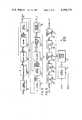
- FIG. 1is a block diagram of an NTSC color broadcast compression and expansion system in accordance with the principles of the present invention.
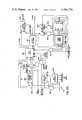
- FIG. 2is a functional block diagram of the scene adaptive coding and decoding method with rate buffer feedback in accordance with the principles of the present invention.
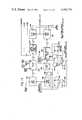
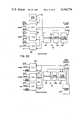
- FIG. 3is a detailed block diagram of the scene adaptive luminance coder and scene adaptive luminance decoder of the system of FIG. 1.
- FIG. 4is a trellis diagram for the discrete cosine transform in one dimension which is implemented in both of the horizontal and vertical consine transformers of the luminance coder of FIG. 4.
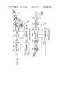
- FIG. 5is a block diagram of the discrete cosine transformer used for the horizontal and vertical cosine transformer of the luminance coder of FIG. 3.
- FIG. 6is a block diagram of a shuffle and add module of the discrete cosine transformer of FIG. 5.
- FIG. 7is a block diagram of a shuffle, multiply and add module of the discrete cosine transformer of FIG. 5.
- FIG. 8is a block diagram of the strip memory in the luminance coder and decoder of FIG. 3.
- FIG. 9is a block diagram of the diagonal access memory in the luminance coder of FIG. 3.
- FIG. 10is a functional graph of the operation of the diagonal access memory of FIG. 9.
- FIG. 11is a block diagram of the encoder in the luminance coder of FIG. 3.
- FIG. 12is a timing diagram for a read coefficient code cycle of the encoder of FIG. 11.
- FIG. 13is a block diagram of the encoder controller in the luminance order of FIG. 3.
- FIG. 14is a state diagram for the encoder controller of FIG. 13.
- FIG. 15is a timing diagram of the encoder controller of FIG. 13.
- FIG. 16is a state table for the encoder controller of FIG. 13.
- FIG. 17is a block diagram of the rate buffer memory in the luminance coder of FIG. 3.
- FIG. 18is a block diagram of the buffer memory controller in the luminance coder of FIG. 3.
- FIG. 19is a timing diagram for control sequences of the buffer memory controller of FIG. 17.
- FIG. 20is a block diagram of the rate normalization processor in the luminance coder of FIG. 3.
- FIG. 21is a flow diagram of calculations performed by the rate normalization processor of FIG. 20.
- FIG. 22is a block diagram of the receive buffer memory in the luminance decoder of FIG. 3.
- FIG. 23is a timing diagram for operational sequences of the receive buffer memory of FIG. 22.
- FIG. 24is a block diagram of the receive buffer memory controller in the luminance decoder of FIG. 3.
- FIG. 25is a block diagram of the Huffman decoder in the luminance decoder of FIG. 3.
- FIG. 26is a state diagram of the Huffman decoder of FIG. 25.
- FIG. 27is a timing diagram of terminal state sequence of the Huffman decoder of FIG. 25.
- FIG. 28is a timing diagram of the zero insertion sequence of the Huffman decoder of FIG. 25.
- FIG. 29is a block diagram of the chrominance encoder and chrominance decoder of the system of FIG. 1.
- FIG. 30is a block diagram of the multiplexer and demultiplexer of the system of FIG. 1.
- FIG. 1A functional block diagram of an NTSC color broadcast compression/expansion system is provided by FIG. 1.
- the systemincludes a composite signal compressor 10.
- a composite signal expander 12is connected to the compressor 10 via a limited bandwidth transmission medium 14.
- the compressor 10includes a standard video interface and sync separator 16 which accepts a composite color video input, extracts vertical and horizontal synchronization signals from the video, and demultiplexes luminance (Y) and chrominance (I,Q) components thereof.
- the separated luminance or monochrome video component along with composite color synchronization informationis provided to a horizontal and vertical dimension cosine transformer 18 and a scene adaptive coder 20 which transform and compress the composite luminance video in accordance with principles of this invention.
- the transformer 18 and coder 20are described later in connection with FIGS. 2-28.
- Separated chrominance componentsare provided to a chrominance encoder 22 which is described in connection with FIG. 29.
- Audiois passed through an audio interface 24 which includes an anti-aliasing filter, and then a standard audio PCM encoder 26 which samples the audio at, e.g., 31.25 KHz/sec. and quantizes the samples to, e.g., 256 levels (8 bits). This generates an, e.g., 250 kilobit/sec. data rate.
- the exemplary sampling rateprovides a standard broadcast quality 15 KHz bandwidth audio channel, and the quantization achieves a 55 dB signal to noise ratio.
- Coded luminance from the scene adaptive coder 20, coded chrominance from the chrominance encoder 22, and coded audio from the PCM encoder 26are combined in a multiplexer 28 in a time division format in which the serial bit stream is divided into frames of, e.g. 32 bits. Each frame begins with a sync bit followed by an audio bit, then 10 bits of chrominance and 20 bits of luminance. Preferably, the frame sync bits are alternated in a repetitive pattern which aids in sync acquisition.
- One entire multiplex frameis reserved for an, e.g., 20 bit "end of block" code which is inserted in a fixed place in the frame to avoid loss of synchronization and catastrophic picture failure in the event of propagation of a bit error. Bit errors can cause incorrect decoding in a way in which code-sync is entirely lost. Use of an end of block code assures restoration of sync without catastrophic picture failure.
- a convolutional codersuch as a rate one half coder 29 and Viterbi decoder 30 may be used.
- the coder 29 and decoder 30are available commercially, and a Linkabit LV 7017A works well.
- the expander 12includes a demultiplexer 32 connected to the Viterbi decoder 20.
- the demultiplexer 32separates audio, chrominance and luminance.
- the luminanceis sent to a scene adaptive decoder 34 and two dimensional inverse cosine transformer 36 which restores the original analog picture field/frame format to the luminance (Y) channel.
- the chrominanceis passed through a two dimensional chrominance interpolator 38, described later in connection with FIG. 29, which inputs out the chroma I and Q subcarriers.
- the chrominance and luminance componentsare recombined, along with recovered picture sync in a video interface and combiner 40 which puts out a composite color signal.
- Audio from the demultiplexer 32is first passed through a PCM digital to analog converter and filter 42 and then an audio output interface 44 which is the symmetrical inverse of the input interface 24.
- the normalization factor with rate buffer feedbackenables a desired variable coding rate for incoming data to be achieved while approaching at all times convergence of an overall desired rate.
- the normalization processcan best be described by mathematical equations written for a 16 pixel (picture element) by 16 pixel block (subframe).
- the quantizeris scaled appropriately according to local image statistics and gives rise to a variable rate coding scheme.
- An appropriate buffering associated with variable rate transform coding on the input and fixed rate channel on the outputthen, adapts the coder 20 to local statistical characteristics of the data.
- the rate bufferwill force the adaptive coder 20 to adjust to the local coding variations while ensuring global performance at the desired level.
- the rate buffer with feedback normalization factoris designed to permit the desired variable coding rate for incoming data while attempting at all times to converge to the overall rate.
- the operationcan best be described by mathematical formulation:
- n(i)number of bits into the rate buffer for the ith block
- ⁇ (k)damping factor at the end of the ith block.
- rate bufferis initially half full.
- the buffer statusis normalized and can swing without ⁇ 0.5.
- initial conditionsare set to
- the number of bits into the buffer for the first block which is a function of the Huffman codecan be represented by ##EQU2## the first term on the right is the number of Huffman code bits into the buffer for the ac coefficients in the first block while the second term accounts for the number of code bits for the dc term.
- the accumulated rateis then simply given by, ##EQU4##
- the average feedback normalization factor at this timeis identical to the initial condition, i.e.,
- the processcarries on block by block basis until the last block of the image is completed.
- a damping factor ⁇ (K)is introduced in Equation (12) to keep the data inside the rate buffer rapidly converging towards the normal half full position.
- the introduction of the damping factornot only keeps the data inside the buffer in rapid convergence but also allows one to use a small size buffer for a practical application.
- the damping factoris strictly dependent upon buffer status and is given by:
- Equation (12)The slope (K) in Equation (12) is estimated from R(K) and D(K) regardless of the input images, as: ##EQU6## This image independent relationship can be derived by modelling the rate and feedback normalization curve as:
- Equations (7) through (12)can be combined to obtain ##EQU7##
- the solution of this difference equationessentially gives the feedback normalization constant D(K) for the required rate R(K) for the K th block.
- the desired operating conditions for the rate buffer algorithmare:
- the condition (b)is key to the performance of the adaptive coder system while the condition (b) is key to the stability of the rate buffer algorithm. These two conditions generally work against each other. However with a proper compromise between them a stable system can be achieved with little loss in image quality. By providing enough dynamic range for the feedback normalization factor D(K) the problem of both the underflow and overflow can be successfully prevented, thereby satisfying the desired operating condition (b) above with a minimum buffer size and a moderate damping factor.
- the scene adaptive coding and decoding components of the compressor 10 and expander 12are functionally depicted in the block diagram of FIG. 2, and are shown architecturally in the structural block diagram of FIG. 3.
- the original imageundergoes a two-dimensional cosine transform in 16 ⁇ 16 pixel (picture element) blocks.
- the resultant transform coefficientsare first normalized at a normalization step 46 by a feedback parameter from a rate buffer.
- the normalized coefficientsare then quantized at a quantization step 48, Huffman coded and run length coded at a coding step 50, and are then rate buffered in a buffering step 52.
- the rate buffering process 52is characterized by a variable data rate input and a constant data output with differentials buffer status fed back to control data quantity at the normalization step 46.
- the received fixed rate dataare converted to a variable rate in a rate buffering step 54.
- the dataare Huffman decoded and run length decoded in a decoding step 56.
- the decoded dataare the inverse normalized at a normalization step 58 by a feedback parameter developed at the buffering step 54.
- An inverse two dimensional discrete cosine transformis then performed by the transformer 36 to reconstruct the spatial picture data.
- the expander rate buffering process 54keeps track of data flow in the same way as is done by the compressor rate buffering step 52. Thus, no overhead is required anywhere throughout the coding and decoding processes.
- Luminance CoderCosine Transformer 18 and Scene Adaptive Coder 20
- the video compressor 10includes in the cosine transformer 18, a horizontal dimension cosine transformer 60, a corner turning strip memory 62, a vertical dimension cosine transformer 64, a diagonal access memory 66, and a transform timing and control element 68.
- the scene adaptive coder 20includes a normalization multiplier 70, a rate normalization processor 72, an encoer 74, an encoder controller 76, a buffer memory 78, and a buffer controller 80, shown diagrammatically with interconnecting data and control signal paths in FIG. 3.
- Luminance DecoderScene Adaptive Decoder 34 and Cosine Transformer 36
- transmitted datais received into a luminance decoder comprising the scene adaptive decoder 34 and inverse cosine transformer 36.
- the decoderincludes an input buffer memory 82, a buffer controller 84, a Huffman/run length decoder 86, a normalization multiplier 88, and a rate normalization processor 90.
- the inverse two dimensional cosine transformer 36includes a diagonal read in memory 92, a vertical dimension inverse cosine transformer 94, a corner turning strip memory 96, a horizontal dimension inverse cosine transformer 98, and a transform timing and control element 100, as shown in FIG. 3 along with interconnecting data and control signal lines.
- the transform processors 60, 66, 94 and 98are the most critical elements of the entire system by virtue of the sheet magnitude of the calculations and speeds requiring to produce the required transform coefficients at NTSC rates.
- the processors 60, 64, 94 and 98are substantially identical to one another and only the horizontal dimension cosine transform processor 60 will be described, it being understood that the other three processors 64, 94 and 98 are substantial duplications of the processor 60.
- the cosine transform processor 60is a modified implementation of a discrete cosine transform algorithm suggested by the coinventors Chen and Fralick and by C. H. Smith in a paper entitled “A Fast Computational Algorithm for the Discrete Cosine Tranform,” published in IEEE Transactions on Communications, September 1977. It is the fastest algorithm known, in the sense that it requires the fewest multiply cycles. Furthermore, it is particularly well-suited to a modular pipelined processor. A trellis diagram for this algorithm is shown in FIG. 4. Computations are grouped into five sets of 16 operations. These five stages are:
- Stage 1Sixteen pairs of input data (F 1x ) points are added or subtracted to result in sixteen intermediate (f 2x ) results. This is called a shuffle and add operation.
- Stage 2This is a second shuffle and add operation with a different shuffling rule operating on f 2x to result in f 3x .
- Stage 4This is another shuffle and add operating on f 4x with a new shuffling rule to result in f 5x .
- Stage 5This is a second shuffle, multiply and add stage with a new shuffling rule and a new set of multiplier constants.
- the resultis F O , the cosine transform.
- the one-dimensional cosine transform processor 60may be implemented from a series of shuffle and add stages and shuffle, multiply and add stages.
- This pipelined conceptis shown diagrammatically in FIG. 5.
- datais passed through a first shuffle and add circuit 102, shown diagrammatically in FIG. 6, and configured to perform the arithmetic operations required at stage 1 of the trellis diagram (FIG. 4).
- a second shuffle and add circuit 104(FIG. 6) performs the operations required at stage 2 (FIG. 4).
- a shuffle, multiply and add circuit 106 shown in FIG. 7,performs the operations required at stage 3 (FIG. 4), and a third shuffle and add circuit 108 performs the operations required at stage 4 (FIG. 4).
- a second shuffle, multiply and add circuit 110performs the calculations required at stage 5 (FIG. 4).
- the entire processor 60is synchronously clocked at the input data rate.
- each stageis provided with a set of control signals which control the stage operation.
- a four bit counter 12 and a control PROM 114are provided to control each stage.
- FIG. 6shows shuffle and add modules 102, 104, 108.
- Dataare loaded into one of the two 16-word dual-port RAM's 116, 118, such as the AMD29705.
- the other RAMis used for the shuffle and add operation.
- the roles of the RAM's 116 and 118are interchanged every 16 clock cycles.
- These RAM's 116, 118have two output ports, each of which may be independently connected to an addressable memory cell.
- port Ais addressed with an "i"
- port Bis addressed with a "j".
- f li and f ljwill appear on the two output ports.
- A"A” port address lines
- B"B” port address lines
- a write-enablean output-enable for each port.
- the twenty-third linedetermines whether the operation of the ALU 124 is "ADD" or "SUBTRACT”. Whenever one of the ports is not enabled, its outputs are held low so that a "0" can be added. This allows transfer of data through the ALU 124 with no operation. It is required twice during each stage but the last; e.g., f 10 and f 115 are transferred directly to f 20 and f 21 .
- FIG. 7shows a shuffle, multiply and add module. It is very similar to the shuffle and add modules 102, 104, 108.
- the shuffle multiply and add modules 106, 110include two dual RAM's 126, 128 and pipeline registers 130, 132.
- a pair of multipliers 134, 136has been included in series between each register 130, 132 and its input port to an ALU 138.
- Each multiplier(which must work faster than the maximum operating speed of single chip multipliers such as the AMD 25LS2516) includes two output latched PROMs 140, 142 and an n-bit adder 144.
- multipliers 134, 136enable each data element to be multiplied by a coefficient prior to adding two products. Because of increased time required to accomplish a multiply operation, the PROMs 140, 142 are provided with pipeline registers in the form of the output latches therein.
- This configuration shown in FIG. 7works because the data to be multiplied are never more than 10 bits wide, and they are always multiplied by a constant which can be selected by 3 bits (i.e., there are never more than 8 distinct constants per stage).
- the multiplicandis split into the 5 most significant bits and the 5 least significant bits. Each half is used to address a look-up table storedin the PROMs 140, 142. Stored in the look-up table are the partial-products of the 5-bit nibble and every possible coefficient (multiplier).
- the control PROM 114generates a 3 bit address corresponding to the coefficient.
- the partial-productsare added in the adder 138.
- the shuffe, multiply and add modules 106, 110require 6 more control lines than the shuffle and add modules 102, 104, 108 in order to specify each of the multipliers.
- the transform control PROM 114is shown in FIG. 5.
- the PROM 114generates each of the control bits during each cycle and the counter 112 addresses the PROM.
- the control cyclerepeats every 32 clocks, and there are 127 lines to be controlled. Hence, the PROM 114 must be at least 32 ⁇ 128 bits.
- the speed of the PROM 114is critical, since it is in series with all pipeline operations. A bipolar PROM with 25 ns access time has been chosen.
- the memory 62 in the transformer 18serves as a temporary buffer between the horizontal transform processor 60 and the vertical transform processor 64. Sixteen horizontal transforms are performed before the first vertical transform. As shown in FIG. 8, the memory 62, 96 comprises four RAMs 140, 142, 144, 146 configured as a double buffer, each buffer being large enough to store a full 16 ⁇ 16 block of coefficients. These fur RAMs 140, 142, 144, 146 are flip-flopped so that, while one pair 140, 142 is being loaded from the horizontal transform processor 60, the other pair 44, 146 is providing the data to the vertical transform processor 64 (FIG. 3).
- Each pair 140, 142 and 144, 146is organized as a 4K by 16 bit matrix in order to carry 16 bits precision for the coefficient data, with 256 coefficients per block.
- a write address counter 148which counts horizontally through the memory 62 is multiplexed by a write multiplexer 150 between the two pairs 140, 142 and 144, 146.
- a read address counter 152is connected through a read multiplexer 154 to count vertically through the two memory pairs.
- Control logic 156enables the read address counter 152 to count vertically.
- An inverter 158is provided in the "write select" line to control the read multiplexer 154.
- Diagonal Acces Memory 66Diagonal Read In Memory 62
- the diagonal access memory 66 shown in the cosine transfrmer 18 of the luminance coder of FIG. 3 (and the equivalent diagonal read in memory 92 of the luminance decoder of FIG. 3)is shown in the detailed block diagram of FIG. 9.
- This memory 66stores a 16 by 16 block of transformed coefficients in rectangular coordinate format (i.e., one 16-point column at a time).
- Each RAM bank 160, 162must be read out in a nonrectangular format, such as illustrated by the diagonal tracing shown in FIG. 10.
- the memoryincludes a rectangular write address counter 164 connected to the bank 160, 162 through a latched multiplexer 166.
- a read address counter 168addresses a PROM 170 in which a non-rectangular address map is stored.
- the address values stored in the PROM 170are passed through a read multiplexer 172 to read the bank 160, 162 non-rectangularly or diagonally as shown in FIG. 10 (the ideal theoretical case).
- the actual read outwill define a random pattern, as the coefficients resulting from (or supplied to) the vertical transform processor 64 (94) are in the order shown in the trellis diagram of FIG. 4.
- One of the RAM banks 160, 162is loaded with a new pixel on every clock pulse.
- the loading addressis generated by the write counter 164, incremented with each clock pulse.
- the other bankis read once each clock cycle from the address put out by the PROM as it is addressed sequentially each clock cycle by the read counter 168.
- the memory 66is under the control of the transformer timing and control module 68 (FIG. 3).
- the transform control module 68(100) shown in FIG. 3 generates all of the required control and clock signals for the transform processors 60, 64, (94), (98), strip memory 62, (96) and diagonal access memory 66 (diagonal read-in memory 92) of the transformer 18, (36).
- the module 68accepts the pixel clock and the sync signals which identify the start of each field and line. It trims the field to 512 by 256 pixels per line, by counting six pixels before it starts the transform process, and by stopping the process 512 pixels later. It also ignores the first three lines in every field and stops the process after 256 lines.
- This modulegenerates clocks and control signals for all other modules of the compressor system 10 (expander system 12).
- the encoder 74is shown in the detailed block and logic diagram of FIG. 11. It accepts the normalized coefficients frm the normalization multiplier 70 (described later in connection with FIG. 19) and encodes them in accordance with a variable length minimum redundancy code, such as a Huffman code and other known and statistically efficient variations thereof such as a truncted Huffman code. If the coefficients are zero, the encoder 74 counts the run length of zeros and encodes this number as a Huffman code.
- a variable length minimum redundancy codesuch as a Huffman code and other known and statistically efficient variations thereof such as a truncted Huffman code.
- the encoder 74includes a coefficient FIFO memory 174 to buffer the speed variations between the COS transformer 18 and the encoder 74.
- Two 256-word PROMs 176, 178respectively, store the Huffman codes corresponding to the coefficients and the run lengths of zero coefficient strings.
- Each PROM 176, 178also stores a 5-bit word which is the length of the code word.
- To speed up the encoding processeach PROM 176, 178 is connected to a corresponding pipeline register 180, 182 which accepts up to 21 bits in parallel and shifts these out serially. A typical read sequence is shown in FIG. 12.
- the coefficient code PROM 176accepts the 8 magnitude bits of the cosine coefficient as an address and outputs up to 21 bits of code plus 5 bits of length to a coefficient length register 184.
- the run-length PROM 178accepts the run length as an address and outputs a similar code and length word to a zero coefficient length register 186.
- the run-length PROM 178is addressed by a zero counter 188 which counts the run length of zero bit strings and selects a code corresponding to that length.
- Three sets of tri-state registers 190, 192, 194 and associated buffers 196, 198, 200are used to generate the end of block (EOB) run length start (RLS) frame sync (FS) codes.
- EOBend of block
- RLSrun length start
- FSframe sync
- the encoder controller 76generates a set of control signals which provide all clocks and enable gating signals to pop a new word out of the FIFO 174, advance the run length counter 18, latch the codes in the shift registers 180, 182 and so on.
- the encoder FIDO 174 outputfeeds an OR gate 206 and a flip flop 208 which generate a control flag F c which is input to the encoder controller 76.
- the encoder controller 76a sequential state machine, is described structurally in FIG. 13. It implements the state diagram shown in FIG. 14. It includes a pipeline register 210 to hold the state, and a high speed Schottky state table logic element 212 to generate the next state and three flags F c , F B and F s in accordance with and as shown in the state table of FIG. 16.
- the controller 76further comprises a frame counter 214 to count picture frames, a block counter 216 to count blocks, a bit counter 218 to provide a bit count, and a length counter 220 to count length of end of bit, run length start and frame sync.
- a two phase clock 222, a shift clock 224, AND gates 226, 228, 230, 232, an OR gate 234, and two flip-flops 236, 238are also part of the controller 76 and are interconnected as shown in FIG. 13. These logical elements provide the control signals required for the encoder 74.
- the timing sequence for the controller 76is shown in FIG. 15. Assume that the state held in the pipeline register 210 has just stabilized. Then, after a few nanoseconds of delay, both the next state and the control variables should have stabilized and are ready for use.
- the first phase of the two-phase clock 222is used with the control variables to generate a set of pulses which advance counters, shift data, and so on in the encoder 74.
- a given state of the controller 76requires that a code be read (e.g., "Read Coeff Code")
- an appropriate pulseis put out to load the correct code into the encoder P/S register 180, and to jam the "Length" word into the preset length counter 220.
- the "length” wordis 2 5 (length in bits of code).
- the state machine 76is temporarily halted by disabling its clock 222, and the code is shifted from the parallel to serial register 180. As it is shifted, the shift pulses are counted in the 5-bit length counter 220. When the counter 220 overflows, shifting is stopped, and the controller clock 224 is enabled.
- the second phase of the clock 224latches the combination of next-state variables and flags which become the new input to the state table logic 212.
- the rate buffer memory 78is shown in block diagram of FIG. 17.
- the rate buffer memory 78comprises an input register 240 which functions to convert the serial data from the encoder 74 into an eight-parallel-bit format which is supplied as a data input to a 32 bit by 8 bit FIFO 242.
- the FIFO 242is supplied with two input control signals: load input FIFO and shift FIFO; and supplies two output flags: FIFO Full and Data Ready.
- the FIFO 242supplies eight bit words stored therein to a 4K by 8 rate buffer memory array 244.
- the array 244is a random access read/write memory and is supplied with a twelve bit address word, a negative chip select control signal (CS) and a negative write enable (read/write) control signal.
- CSnegative chip select control signal
- read/writeread/write
- the serial to parallel register 240is supplied with a clocking signal ⁇ S from the encoder controller 76 while the output parallel to serial register 246 is supplied with a different clocking signal ⁇ D also from the encoder controller 76. It is to be understood that the clocking signal ⁇ S supplied to the input register 240 is a different asynchronus clocking signal from the clocking signal ⁇ D supplied to the output parallel to serial register 246.
- the input data arriving at the serial to parallel register 240may arrive at any time in the encoder output cycle, and the output data must be loaded into the output register 246 synchronously once every eight bits, the input data must occasionally wait to be written into the memory 244; for this reason the 32 by 8 bit FIFO 242 is supplied to compensate for such timing variations.
- an eight bit sync wordmay be inserted between every 512 output bits of serial data from the eight bit parallel serial register 246 of the buffer memory 78.
- This wordconsists of alternating "sync" bit which is utilized to synchronize the decoder 34.
- Six bits of the wordare a binary count to the first bit of the next Huffman Code and a parity calculated over the seven bits.
- the eight bit sync wordmust be stored until the proper time for insertion into the output serial data stream.
- This functionis accomplished by the following elements shown in FIG. 17: an eight bit synchronous counter 248, a six bit counter 250, a parity coder 252, an error control 32 by 8 FIFO 254, and a second eight bit parallel to serial output shift register 256 which has its output connected parallel with the output from the output shift register 246 in a tri-state bus configuration.
- the interleaving of the sync word with the serial data streamis timed and controlled by the memory controller 80 which will be described hereinafter. Additional logic elements are required for the proper functioning of the error control circuit and these include three D type flip flops 258, 260, 262 and AND gates 264, 266, 268, and 270, all configured as shown in FIG. 16.
- the buffer memory controller 80is shown in the detailed block diagram of FIG. 18.
- the buffer controller 80interfaces to the encoder controller 76 to assure that the encoder 74 does not try to shift data to the buffer memory 78 when it is busy.
- the controller 80als interfaces to the multiplexer 28 (FIG. 1) accepting timing signals, so that the luminance data stream may be properly interleaved with the chrominance, sound and sync data.
- the controller 80functions to generate the required control signals and clocks operate the buffer memory by accomplishing four sequences to be described below and shown in FIG. 19. These four sequences are output read cycle, sync insertion sequence, load input FIFI sequence, and input write cycle.
- the buffer controller 80provides a controller for the buffer memory FIFO 242 which includes a programmable counter 272, a flip flop 274, a four bit counter 276, an AND gate 278, and an OR gate 280 to provide the load input FIFO control signals to the FIFO 242 and generate a wait state when it is full.
- Other elements of the buffer controller 80include a two phase data rate clock 282, a four bit counter 284, a read flip flop 286, a write flip flop 288, a five bit counter 290, an insert sync flip flop 292, a read address counter of twelve bits 294, and a write address counter of twelve bits 296, to provide read/write addresses to the memory 78.
- Other control signal producing logic elements of the controller 80include AND gates 298, 300, 302, 304, 306, and 308.
- An OR gate 310 and an inverter 312make up the balance of logic elements for the controller 40. These elements 298-312 are configured as shown in FIG. 17 to produce the control signals desired.
- the output read cycle control sequencemust be accomplished synchronously with the output data once every eight bits, and so it may be regarded as a master cycle taking precedence over the other cycles.
- the buffer memory output register 246(FIG. 17) is shifted, the shift pulses are counted by the four bit counter 284.
- the counter 284overflows and sets the read flip flop 286 which together with the two phase clock 282 generate the chip select (CS) and load shift register pulses. These pulses enable the buffer memory 244 to be read and to load the output shift register 246.
- CSchip select
- sync insertion sequencesare provided once every 512 bits (64 bytes). At such occurrence the sync word is interleaved into the data stream by operation of the sync word register 256. The output read cycle is inhibited for eight bits while the interleaving of the sync word is accomplished.
- the five bit counter 290counts the output bytes and generates the required control signals when it overflows and sets the sync flip flop 292.
- the load input FIFO sequenceoccurs when the buffer memory input shift register 240 fills which occurs once every eight bits. At this point, it is loaded into the FIFO 242.
- the four bit counter 276counts the input bits and halts the encoding process long enough to load the FIFO 242 when the eighth bit occurs. If the FIFO fills, the encoding process is stopped by a wait state generated through the OR gate 280 until the word is loaded from the FIFO 242 into the memory 244.
- the input write cycleoccurs whenever the FIFO 242 has data ready to load into the memory 244 and it is not then being read. This cycle is initiated by the FIFO "data ready" signal supplied to the AND gate 300, passed through the flip flop 288 and returned to the memory 244 as a write enable (WE) signal from the gate 306. Also the inverting input of gate 248 is connected to the input of gate 254. The input read cycle is inhibited during the output write cycle.
- the read address counter 294contains the address of the next data output byte while the write address counter 296 points to the next input byte.
- the read address counter 294is enabled and clocked whenever the output is read.
- the write address counter 296is enabled and clocked whenever input data is written.
- the buffer feedback controlled state normalization multiplier 70 and processor 72are shown in FIG. 20. Their function is to calculate the normalization factor 1/D K for each block of the input transform coefficient in real time. The computation is based on the last value of D and the number of bits loaded into the rate buffer memory 78 during the last block or subframe.
- R odesired synchronous output bit rate
- R Idesired synchronous input bit rate
- the calculations set forth in the flow diagram of FIG. 21require the use of eight of sixteen bit registers for storage of intermediate results and recursive constants.
- the calculationsrequire the following arithmetic operations on two sixteen bit numbers: five additions, three multiplies and two divides.
- the rate normalization processor 72comprises four bipolar bit-slice MPUs 314, 316, 318 and 320, such as the AMD 2903, as shown in FIG. 20. These four bit-slice processors 314, 316, 318, 320 are connected with lookahead carry and are used in a pipeline control architecture for maximum speed.
- a microprogram controller 322AMD type 2910
- a 256 by 40 bit microprogram memory 324are provided to control the operation of the processors 314, 316, 318 and 320.
- the rate normalization processor 72also includes a 32 by 8 bit interrupt vector map 326, a pipeline register 328, a constant PROM 330, a decoder 332, a status and shift control 334 (AMD type 2904), a look ahead carry 336 (AMD 2902), and four latches 338, 340, 342 and 344, all configured as shown in FIG. 20.
- the processor 70operates with four external interrupts: a power up restart, a change rate, a bit count ready, and block transform done, all supplied to the vector interrupt map 326. Each of these interrupts vector the program stored in the memory 324 to the appropriate subroutine shown in FIG. 21.
- the power up restartstarts the initialization process which loads the initial values of the constants R o /R I , D o , D I (1.5-S -1 ) and (S o -S -1 ) into appropriate registers, and outputs 1/D o .
- the "change rate" interruptcauses the processor 72 to read an external i/o port which contains the desired value of R o /F I , and then initializes all other constants.
- the change rate interruptenables an operator to vary the input and output rates.
- the bit count ready interruptcauses the processor 72 to input a new value of bit count ( ⁇ ), and calculates a new value of 1/D. This value is then stored awaiting the end of the block transform interrupt. This latter interrupt transfers the new value of 1/D to the output latch 344.
- the decoder buffer memory 82is shown in the block diagram of FIG. 22 which reads from right to left.
- the expander buffer memory 82functions to buffer the input serial data received from the communications channel 14 to accommodate the operation of the Huffman decoder 86, normalization multiplier 88 and processor 90, and inverse transformer 36 (FIG. 3).
- the buffer 82converts the input serial data into a parallel format, stores the data and then reconverts the data back into a serial format. Thus, it includes a serial to parallel register 346, an eight bit latch 348, a rate buffer memory array 350, a 32 by 8 bit FIFO 352, and a parallel to serial register 354.
- the eight bit latch 348is provided as a buffer between the serial to parallel register 346 and the rate buffer memory array 350. This latch 348 functions to pipeline input data into the memory 350. Furthermore, to put out data asynchronously as rapidly as needed and so as not to interfere with the input write cycle, the 32 word FIFO 352 is provided between the rate buffer memory 350 and the output parallel to serial register 354.
- the control sequenceis to write data into the memory 350, read data from the memory 350 and load the output shift register 354 as shown in the sequences timing chart in FIG. 23.
- the timing shown in FIG. 23writes one eight bit byte and then reads none, one or two eight bit bytes while the input shift register 346 is accepting eight bits. Then the eight bit latch 348 latches the input data.
- the state of the output FIFO 352determines how many bytes are read. When the output FIFO 352 is full, no more bytes will be read. Until the FIFO 352 is full, two bytes will be read as shown in FIG. 23.
- the FIFO 352is emptied as rapidly as the Huffman decoder 86 can decode the data received from the register 354 and generate coefficients which will then be inversely transformed in the decoder transformer 36.
- the decoder buffer controller 84is shown in FIG. 24.
- the controller 84generates all of the timing signals necessary to control the decoder buffer memory 82.
- the controller 84includes a two phase clock 356 synchronized to the data clock and the logic elements required to generate the control signals shown in FIG. 22.
- the controller 84includes a four bit counter 358, a write flip flop 360, and an AND gate 362 which provide the latch control signal.
- Two flip flops 364 and 366 along with an OR gate 368are configured to provide a write enable (WE) control signal.
- a write address counter 370 and a read address counter 372provide the necessary addressing for the memory array 350 (FIG. 22).
- the load FIFO signalis provided by the combination of AND gate 374, 376, and 378 along with two flip flops 380 and 382.
- the operation of the read address counteris enabled by an AND gate 384.
- the load shift register signalis provided by a counter 386 to which a flip flop 388 is connected to provide the shift FIFO control signal.
- a synchronizerwould be connected to the memory 82 and controller 84 to decode error control sync generated by the scene adaptive coder in a stand-alone system. It would monitor the input data stream to obtain sync from the error control byte inserted by the coder 20 as described above. The synchronizer would also read the six bit portion of the sync word which contains the count to the start of the next Huffman code. The synchronizer would generate a signal which resets the Huffman decoder 86 to a "start" state thus assuring periodically that it is and remains in sync with the incoming data.
- the synchronizeris implemented as a high speed hardware processor.
- the Huffman decoder 86is shown in the detailed block and logic diagram of FIG. 25.
- a decoder state diagram for a typical Huffman codeis shown in FIG. 26.
- the decoder 86has been implemented as a finite state machine which functions instantaneously to decode each bit as it is received. This approach is required because the data arriving at the decoder 86 from the buffer memory 82 (and synchronizer) is in a serial data stream format of a sequence of Huffman codes which must be decoded very rapidly.
- the Huffman coderesults in coefficient words at variable length. The length is not known to the decoder 86 until the word has been decoded.
- the decoderis seen to include a decoder PROM 390 which receives the input data in serial format, a ten bit latch 392 which functions to address the decoder PROM 390, a FIFO 394 which receives decoded coefficients from the decoder PROM and stores them, a two bit decoder 396 which functions to decode the end of bit signal (EOB) and frame sync signal (FS), an output selector 398 which receives eight parallel bits from the FIFO 394 or eight zero bits and selects between them in accordance with the nature of the output coefficient.
- the encoder 86further includes an eight bit counter 400 to which a dual D flip flop 402 and two AND gates 404 and 406 are connected, a logic element 408 which implements the following logic equations:
- Additional circuitry of the decoderincludes three AND gates 412, 414 and 416, an operator selector control circuit 418, and a serial to parallel register 420 which provides outputs for compression, frame rate and resolution control.
- the decoder 86sequentially decodes the input serial bit stream, one bit at a time with the 2 K by 12 PROM 390 which implements the state diagram of FIG. 26. From the state diagram, it is clear that a decision of the new state can be made knowing old state and the next bit.
- the output of the decoder 86is captured in the latch 392 and is used with the next bit to address the PROM 390 which implements the state diagram of FIG. 26.
- the new statehas been preprogrammed into the PROM 390 and it is then put out as the old state for the next bit.
- the latch 392must be strobed once per bit, if the bit is to be decoded, and so it is connected to the sync clock input.
- the decoder 86must decode two Huffman codes, each with 256 words. It can be shown that a "tree" diagram, such as that shown in FIG. 26, requires less than 512 states to decode a 256 word code, hence a total of 1 K states are required, no more.
- the statesare numbered so that the least-significant eight bits of the ten bits determining the state for the terminal states are either the coefficient of the coded cosine coefficient, or they are the run length of the run length, depending on the code word.
- the eight least significant bits and two control bitsare loaded into the FIFO.
- the next data bitis also loaded into the FIFO 394.
- the two control bitsare used to designate the nature of the code word: frame sync, end of block, coefficient, or run length. These are programmed into the PROM 390 as part of the state diagram implementation shown in FIG. 26.
- the FIFO 394acts to separate the operation of the decoder 86 which must operate asynchronously from the inverse cosine transformer 36 which operates synchronously with the video output.
- the control bitsare decoded by the two bit decoder 396 to generate the end of bit and frame sync signals. If a run length has been decoded, the appropriate number of zero value coefficients are generated by operation of the eight bit counter 400, dual D flip flops 402 and logic 408. These coefficients are inserted into the coefficient stream by operation of the two to one output selector 398. The timing sequence for zero insertion is shown in FIG. 28.
- the chrominance encoder 22 and chrominance decoder 38are shown in FIG. 29.
- the encoder 22operates on the separated I and Q analog signals to produce an encoded digital bit stream at an average rate of 0.375 bits per pixel. This is accomplished by sampling I and Q chrominance components at the full bandwidth pixel rate with eight quantization levels per pixel.
- the digitized chrominanceis then filtered and down-sampled along the scan line to achieve a 4 to 1 bit rate reduction. Filtering in the vertical dimension is achieved by averaging pairs of lines, and temporal filtering is realized by recoding only I data for, e.g., odd-line fields and only Q data for even-line fields.
- the chrominance signalsare sampled at full bandwidth rates and all filtering operations are performed digitally using finite impulse response techniques capable of perfect phase linearity.
- the I and Q chrominance signalsare first applied to a 2 to 1 multiplexer 424 which selects the I signal for odd line fields and the Q signal for even line fields. This selection is followed by a buffer amplifier 426 which provides a low source impedance signal to an analog to digital converter 428.
- a high speed parallel or flash 3 bit converter 428is used which eliminates any need for a sample and hold circuit. Standard modules such as the Datel MX808 multiplexer, AM-102A buffer amplifier and HU38MC A/D are used for the multiplexer 424, amplifier 426 and converter 428.
- the digitized dataare averaged along the scan line in blocks of 4 pixels and vertically over two lines by an ALU 430 formed, for example, of two 74LS181 integrated circuits and associated control logic.
- ALU 430formed, for example, of two 74LS181 integrated circuits and associated control logic.
- 4 pixelsare added to form a 5-bit sum which is stored in a line buffer 432 after passing through a multiplexer 434.
- the processis repeated for all 464 pixels to be processed in a line, on the next scan in the field, the 4 pixel sums are formed as before and added to the corresponding sum from the line buffer 432 to form a 6-bit sum of 8 pixels.
- the three most significant bits of this 8 pixel sumare then loaded from the ALU 430 to an output FIFO buffer 436 via the multiplexer 434.
- a controller 438 for the ALU 430 and an output parallel to serial shift register 440are also required for the encoder 22, as shown in FIG. 29.
- the chrominance decoder 38 shown in FIG. 29performs the inverse function of the encoder 22. Since the I chrominance component is encoded and transmitted for, e.g., the odd-line fields and the Q component for the evenline fields, it is necessary to store in a field buffer memory 442 the previous field of chrominance data (in compressed form) to provide the I and Q data for each reconstructed pixel. Every other line in the regenerated field is interpolated from its adjacent lines. This interpolation is accomplished with a single ALU chip 444 which is connected to the field buffer 442 through a latching demultiplexer 446.
- the reconstructed line chrominance data(still compressed 4 to 1 horizontally) is fed to an output FIFO buffer 448 for sequential I, Q pairs. These data are then retrieved from the FIFO 448, demultiplexed into separate I and Q channels, expanded horizontally and converted to the analog domain in a digital to analog converter 450.
- a controller 452 and an input serial to parallel shift register, buffer 454are also required for the decoder 38 in the configuration shown in FIG. 29.
- the multiplexer 28accepts the three coded signals: luminance, chrominance and sound, into three FIFO buffer memories 456, 458, 460.
- the outputs of these memories 456, 458, 460are combined with a sync word from a sync generator 462 into a single composite data stream by a selector 464.
- Video syncis carried within luminance data.
- a five bit frame counter 466 and a selector control PROM 468are provided to control the selector 464.
- the demultiplexer 32accepts the data stream, and it separates out the sync word with a synchronizer 470 which synchronizes operation of the entire expander 12 to the incoming data stream.
- the incoming datais provided to selector 472 which separates luminance, chrominance and audio data and loads the data into three elastic buffers 474, 476, 478. These buffers are emptied at a constant rate by the scene adaptive decoder 34, the chrominance decoder 38 and the audio decoder 42 (FIG. 1) already described.
- the selector 472requires a five bit frame counter 480 and a selector mapping PROM 482, for locating sync words and directing data to the FIFOs 474, 476, 478.
Landscapes
- Engineering & Computer Science (AREA)
- Multimedia (AREA)
- Signal Processing (AREA)
- Computing Systems (AREA)
- Theoretical Computer Science (AREA)
- Compression Or Coding Systems Of Tv Signals (AREA)
Abstract
Description
D(1)=D(1)=D (4)
R(2)=R[1.0-S(1)] (5)
D(2)=α(d) [R(2)=R(1)]+D(1) (6)
(K)=1+θS(K) (13)
RD=C (15)
dD/dR·R/D=-1
α=dD/dR=-(D/R) (16)
D.sub.1 =(Q.sub.1 ∩Q.sub.2 ∪Q.sub.1 ∩Q.sub.2 ∩ZC) (21)
D.sub.2 =(Q.sub.1 ∩Q.sub.2 (∪) Q.sub.1 ∩Q.sub.2 ∩OF), (22)
Claims (11)
Priority Applications (1)
| Application Number | Priority Date | Filing Date | Title |
|---|---|---|---|
| US06/277,981US4394774A (en) | 1978-12-15 | 1981-06-26 | Digital video compression system and methods utilizing scene adaptive coding with rate buffer feedback |
Applications Claiming Priority (2)
| Application Number | Priority Date | Filing Date | Title |
|---|---|---|---|
| US05/969,991US4302775A (en) | 1978-12-15 | 1978-12-15 | Digital video compression system and methods utilizing scene adaptive coding with rate buffer feedback |
| US06/277,981US4394774A (en) | 1978-12-15 | 1981-06-26 | Digital video compression system and methods utilizing scene adaptive coding with rate buffer feedback |
Related Parent Applications (1)
| Application Number | Title | Priority Date | Filing Date |
|---|---|---|---|
| US05/969,991ContinuationUS4302775A (en) | 1978-12-15 | 1978-12-15 | Digital video compression system and methods utilizing scene adaptive coding with rate buffer feedback |
Publications (1)
| Publication Number | Publication Date |
|---|---|
| US4394774Atrue US4394774A (en) | 1983-07-19 |
Family
ID=26958825
Family Applications (1)
| Application Number | Title | Priority Date | Filing Date |
|---|---|---|---|
| US06/277,981Expired - LifetimeUS4394774A (en) | 1978-12-15 | 1981-06-26 | Digital video compression system and methods utilizing scene adaptive coding with rate buffer feedback |
Country Status (1)
| Country | Link |
|---|---|
| US (1) | US4394774A (en) |
Cited By (196)
| Publication number | Priority date | Publication date | Assignee | Title |
|---|---|---|---|---|
| US4467346A (en)* | 1981-03-11 | 1984-08-21 | Fuji Photo Film Co., Ltd. | Adaptive quantizer |
| FR2575351A1 (en)* | 1984-12-21 | 1986-06-27 | Thomson Csf | ADAPTIVE METHOD FOR ENCODING AND DECODING A TRANSFORMATION IMAGE SUITE, AND DEVICES FOR IMPLEMENTING SAID METHOD |
| US4622585A (en)* | 1983-04-11 | 1986-11-11 | U.S. Philips Corporation | Compression/decompression system for transmitting and receiving compressed picture information arranged in rows and columns of pixels |
| EP0201679A1 (en)* | 1985-04-17 | 1986-11-20 | Siemens Aktiengesellschaft | Method for reducing the image data of digital television signals |
| US4661849A (en)* | 1985-06-03 | 1987-04-28 | Pictel Corporation | Method and apparatus for providing motion estimation signals for communicating image sequences |
| WO1987005178A1 (en)* | 1986-02-18 | 1987-08-27 | Deutsche Thomson-Brandt Gmbh | Method for digital data transmission |
| US4698689A (en)* | 1986-03-28 | 1987-10-06 | Gte Laboratories Incorporated | Progressive image transmission |
| US4703350A (en)* | 1985-06-03 | 1987-10-27 | Picturetel Corporation | Method and apparatus for efficiently communicating image sequences |
| US4703349A (en)* | 1985-03-19 | 1987-10-27 | Picturetel Corporation | Method and apparatus for multi-dimensional signal processing using a Short-Space Fourier transform |
| US4717956A (en)* | 1985-08-20 | 1988-01-05 | North Carolina State University | Image-sequence compression using a motion-compensation technique |
| US4727495A (en)* | 1984-10-08 | 1988-02-23 | The General Electric Company, P.L.C. | Data communication system |
| US4727422A (en)* | 1985-06-03 | 1988-02-23 | Picturetel Corporation | Method and apparatus for efficiently communicating image sequence having improved motion compensation |
| US4729020A (en)* | 1987-06-01 | 1988-03-01 | Delta Information Systems | System for formatting digital signals to be transmitted |
| US4754492A (en)* | 1985-06-03 | 1988-06-28 | Picturetel Corporation | Method and system for adapting a digitized signal processing system for block processing with minimal blocking artifacts |
| US4764805A (en)* | 1987-06-02 | 1988-08-16 | Eastman Kodak Company | Image transmission system with line averaging preview mode using two-pass block-edge interpolation |
| US4772956A (en)* | 1987-06-02 | 1988-09-20 | Eastman Kodak Company | Dual block still video compander processor |
| US4774587A (en)* | 1987-06-02 | 1988-09-27 | Eastman Kodak Company | Still video transceiver processor |
| US4777620A (en)* | 1985-02-20 | 1988-10-11 | Elscint Ltd. | Data compression system |
| US4780761A (en)* | 1987-06-02 | 1988-10-25 | Eastman Kodak Company | Digital image compression and transmission system visually weighted transform coefficients |
| US4794464A (en)* | 1986-09-02 | 1988-12-27 | Eastman Kodak Company | Video time division multiplexer with plural dual port memories |
| US4802232A (en)* | 1986-03-14 | 1989-01-31 | Ant Nachrichtentechnik Gmbh | Method for reducing the quantity of data in image coding |
| US4816914A (en)* | 1987-01-07 | 1989-03-28 | Pictel Corporation | Method and apparatus for efficiently encoding and decoding image sequences |
| US4816901A (en)* | 1988-04-27 | 1989-03-28 | Universal Video Communications Corp. | Method and system for compressing color video data |
| EP0309280A1 (en)* | 1987-09-23 | 1989-03-29 | BRITISH TELECOMMUNICATIONS public limited company | Video coder |
| FR2621194A1 (en)* | 1987-09-29 | 1989-03-31 | Labo Electronique Physique | DEVICE FOR ENCODING DIGITAL VIDEO SIGNALS |
| US4827338A (en)* | 1985-10-22 | 1989-05-02 | Eude Gerard | Hybrid coding process by transformation for the transmission of picture signals |
| US4843466A (en)* | 1988-04-27 | 1989-06-27 | Universal Video Communications Corp. | Method and system for decompressing color video slope encoded data |
| EP0322058A1 (en)* | 1987-12-23 | 1989-06-28 | Philips Electronique Grand Public | Arrangement for regulating the transmission speed of at least two components of digital video signals |
| US4845662A (en)* | 1982-11-11 | 1989-07-04 | Tokyo Shibaura Denki Kabushiki Kaisha | Data processor employing run-length coding |
| EP0323362A1 (en)* | 1987-12-30 | 1989-07-05 | Thomson Grand Public | Adaptive method of transform coding and decoding a sequence of pictures, and devices for carrying out this method |
| US4847677A (en)* | 1988-04-27 | 1989-07-11 | Universal Video Communications Corp. | Video telecommunication system and method for compressing and decompressing digital color video data |
| US4849807A (en)* | 1988-04-27 | 1989-07-18 | Universal Video Communications Corp. | Method and system for compressing color video feature encoded data |
| US4849810A (en)* | 1987-06-02 | 1989-07-18 | Picturetel Corporation | Hierarchial encoding method and apparatus for efficiently communicating image sequences |
| US4857991A (en)* | 1988-04-27 | 1989-08-15 | Universal Video Communications Corp. | Method and system for decompressing color video feature encoded data |
| US4857993A (en)* | 1988-04-27 | 1989-08-15 | Universal Video Communications Corp. | Method and system for decompressing digital color video statistically encoded data |
| US4894710A (en)* | 1986-12-17 | 1990-01-16 | Telettra Telefonia Elettronica E Radio S.P.A. | System for processing color television signals with amplitude modulation encoded chrominance information |
| US4897717A (en)* | 1988-03-30 | 1990-01-30 | Starsignal, Inc. | Computer-based video compression system |
| US4901075A (en)* | 1986-09-13 | 1990-02-13 | U. S. Philips Corporation | Method and apparatus for bit rate reduction |
| US4903020A (en)* | 1987-10-06 | 1990-02-20 | Ant Nachrichtentechnik Gmbh | Method and apparatus for digitally processing stored compressed analog signals |
| US4914508A (en)* | 1988-04-27 | 1990-04-03 | Universal Video Communications Corp. | Method and system for compressing and statistically encoding color video data |
| US4922273A (en)* | 1987-04-02 | 1990-05-01 | Konica Corporation | Compression method of halftone image data |
| FR2638926A1 (en)* | 1988-11-10 | 1990-05-11 | Labo Electronique Physique | Method and device for digital coding of high-definition television pictures; corresponding decoding device, picture transmission system equipped with a stage for transmission and one for reception including such a device for coding or decoding transmission and reception stages comprising such devices |
| US4933763A (en)* | 1988-02-29 | 1990-06-12 | U.S. Philips Corporation | Method of and arrangement for coding digital video signals and corresponding decoding arrangement |
| US4937573A (en)* | 1986-11-04 | 1990-06-26 | Telettra Telefonia Elettronica E Radio Spa | Variable length code and devices for high frequency transmission |
| US4939515A (en)* | 1988-09-30 | 1990-07-03 | General Electric Company | Digital signal encoding and decoding apparatus |
| US4979039A (en)* | 1989-01-30 | 1990-12-18 | Information Technologies Research Inc. | Method and apparatus for vector quantization by hashing |
| US4985784A (en)* | 1988-02-05 | 1991-01-15 | Hitachi, Ltd. | Image data transfer method and apparatus therefor |
| US4989089A (en)* | 1988-11-08 | 1991-01-29 | U.S. Philips Corporation | Television picture coding device and corresponding decoding device, a television picture transmission system incorporating such devices, and transmission and receiving stages of such a system |
| EP0303978A3 (en)* | 1987-08-21 | 1991-01-30 | Deutsche Thomson-Brandt GmbH | Method and circuit for enhancing the resolution of digital signals |
| EP0304836A3 (en)* | 1987-08-26 | 1991-01-30 | Deutsche Thomson-Brandt GmbH | Method and circuit concerning the resolution of digital signals |
| US4999715A (en)* | 1989-12-01 | 1991-03-12 | Eastman Kodak Company | Dual processor image compressor/expander |
| US5008949A (en)* | 1983-08-30 | 1991-04-16 | Canon Kabushiki Kaisha | Image processing system |
| FR2657738A1 (en)* | 1990-01-30 | 1991-08-02 | Philips Electronique Lab | Device for variable-length coding of digital signals |
| US5038202A (en)* | 1987-05-13 | 1991-08-06 | Ricoh Company, Ltd. | Image transmission system |
| EP0442548A1 (en)* | 1990-01-30 | 1991-08-21 | Laboratoires D'electronique Philips S.A.S. | Variable length coding and decoding devices for digital data |
| WO1991012590A1 (en)* | 1990-02-09 | 1991-08-22 | Aware, Inc. | Improved method and apparatus for representing an image |
| US5045925A (en)* | 1989-02-16 | 1991-09-03 | Fuji Photo Film Co., Ltd. | Apparatus for achieving compression encoding on components of image signal |
| WO1991014339A1 (en)* | 1990-03-15 | 1991-09-19 | Thomson Consumer Electronics S.A. | Digital image coding with quantization level computation |
| WO1991014295A1 (en)* | 1990-03-15 | 1991-09-19 | Thomson Consumer Electronics S.A. | Digital image coding using a random scanning of image frames |
| WO1991014342A1 (en)* | 1990-03-16 | 1991-09-19 | Information Technologies Research, Inc. | Method and apparatus for vector quantization |
| WO1991014340A1 (en)* | 1990-03-15 | 1991-09-19 | Thomson Consumer Electronics S.A. | Digital image processing including block edges filtering |
| US5054103A (en)* | 1987-09-24 | 1991-10-01 | Matsushita Electric Works, Ltd. | Picture encoding system |
| FR2662318A1 (en)* | 1990-05-15 | 1991-11-22 | Philips Electronique Lab | Variable-length decoding device for digital signals |
| US5079631A (en)* | 1989-03-24 | 1992-01-07 | U.S. Philips Corporation | Device for encoding digital video signals including means for classifying the video signals into distinct families prior to normalization and quantization |
| US5111292A (en)* | 1991-02-27 | 1992-05-05 | General Electric Company | Priority selection apparatus as for a video signal processor |
| US5122875A (en)* | 1991-02-27 | 1992-06-16 | General Electric Company | An HDTV compression system |
| US5128754A (en)* | 1990-03-30 | 1992-07-07 | New York Institute Of Technology | Apparatus and method for encoding and decoding video |
| US5146324A (en)* | 1990-07-31 | 1992-09-08 | Ampex Corporation | Data compression using a feedforward quantization estimator |
| US5168356A (en)* | 1991-02-27 | 1992-12-01 | General Electric Company | Apparatus for segmenting encoded video signal for transmission |
| EP0487282A3 (en)* | 1990-11-19 | 1992-12-30 | Canon Kabushiki Kaisha | Image processing apparatus |
| US5185599A (en)* | 1987-10-26 | 1993-02-09 | Tektronix, Inc. | Local display bus architecture and communications method for Raster display |
| EP0427108A3 (en)* | 1989-11-06 | 1993-03-03 | Mitsubishi Denki Kabushiki Kaisha | Picture coding apparatus |
| US5216516A (en)* | 1990-04-27 | 1993-06-01 | Ricoh Company, Inc. | Orthogonal transformation arithmetic unit |
| US5235623A (en)* | 1989-11-14 | 1993-08-10 | Nec Corporation | Adaptive transform coding by selecting optimum block lengths according to variatons between successive blocks |
| EP0472961A3 (en)* | 1990-08-31 | 1993-10-20 | Samsung Electronics Co Ltd | Coding method for increasing compressing efficiency of data in transmitting or storing picture signals |
| US5293434A (en)* | 1991-04-10 | 1994-03-08 | International Business Machines Corporation | Technique for use in a transform coder for imparting robustness to compressed image data through use of global block transformations |
| US5301018A (en)* | 1991-02-13 | 1994-04-05 | Ampex Systems Corporation | Method and apparatus for shuffling image data into statistically averaged data groups and for deshuffling the data |
| EP0583107A3 (en)* | 1992-07-31 | 1994-05-18 | Canon Kk | Image processing method and apparatus |
| US5337085A (en)* | 1992-04-10 | 1994-08-09 | Comsat Corporation | Coding technique for high definition television signals |
| US5339108A (en)* | 1992-04-09 | 1994-08-16 | Ampex Corporation | Ordering and formatting coded image data and reconstructing partial images from the data |
| FR2702580A1 (en)* | 1993-03-09 | 1994-09-16 | Blondel Gerard | Process for compressing a digital image to a predetermined size, and corresponding decompression process |
| US5359675A (en)* | 1990-07-26 | 1994-10-25 | Ronald Siwoff | Video spectacles |
| US5365272A (en)* | 1992-06-19 | 1994-11-15 | General Electric Company | Method for formatting compressed video data into transport cells |
| US5367629A (en)* | 1992-12-18 | 1994-11-22 | Sharevision Technology, Inc. | Digital video compression system utilizing vector adaptive transform |
| US5371811A (en)* | 1987-07-09 | 1994-12-06 | British Telecommunications Public Limited Company | Data encoding |
| US5379380A (en)* | 1989-03-28 | 1995-01-03 | Matsushita Electric Industrial Co., Ltd. | System with dedicated buffers connected to respective I/O devices for continuous processing of digital data |
| USRE34824E (en)* | 1987-09-23 | 1995-01-10 | British Telecommunications Public Limited Company | Video coder |
| US5389965A (en)* | 1993-04-01 | 1995-02-14 | At&T Corp. | Video telephone station having variable image clarity |
| EP0609985A3 (en)* | 1993-01-15 | 1995-02-15 | Canon Kk | Compression factor adjustment to facilitate image display. |
| US5392223A (en)* | 1992-07-29 | 1995-02-21 | International Business Machines Corp. | Audio/video communications processor |
| US5404446A (en)* | 1992-03-26 | 1995-04-04 | International Business Machines Corporation | Dual buffer video display system for the display of asynchronous irregular frame rate video data |
| US5414804A (en)* | 1989-10-16 | 1995-05-09 | Hughes Aircraft Company | Fast image decoder |
| US5418571A (en)* | 1991-02-01 | 1995-05-23 | British Telecommunicatons Public Limited Company | Decoding of double layer video signals with interpolation replacement on missing data from enhancement layer |
| US5424733A (en)* | 1993-02-17 | 1995-06-13 | Zenith Electronics Corp. | Parallel path variable length decoding for video signals |
| US5434623A (en)* | 1991-12-20 | 1995-07-18 | Ampex Corporation | Method and apparatus for image data compression using combined luminance/chrominance coding |
| US5442399A (en)* | 1990-06-25 | 1995-08-15 | Mitsubishi Denki Kabushiki Kaisha | Method and apparatus for coding a digital video signal by formatting the signal into blocks |
| US5450602A (en)* | 1992-12-04 | 1995-09-12 | International Business Machines Corporation | Two stage register for capturing asynchronous events and subsequently providing them to a processor without loss or duplication of the captured events |
| US5485533A (en)* | 1990-06-13 | 1996-01-16 | Mitsubishi Denki Kabushiki Kaisha | Method and apparatus for encoding video signals in 3-D blocks without detecting image motion |
| US5508949A (en)* | 1993-12-29 | 1996-04-16 | Hewlett-Packard Company | Fast subband filtering in digital signal coding |
| AP504A (en)* | 1993-09-08 | 1996-07-01 | Idt Inc | Computer compression of video images. |
| US5533140A (en)* | 1991-12-18 | 1996-07-02 | U.S. Philips Corporation | System for transmitting and/or storing signals corresponding to textured pictures |
| US5544338A (en)* | 1992-12-31 | 1996-08-06 | International Business Machines Corporation | Apparatus and method for raster generation from sparse area array output |
| US5563961A (en)* | 1994-03-03 | 1996-10-08 | Radius Inc. | Video data compression method and system which measures compressed data storage time to optimize compression rate |
| EP0712095A3 (en)* | 1994-10-28 | 1996-10-30 | Seiko Epson Corp | Method and device for image data compression |
| US5577190A (en)* | 1991-12-13 | 1996-11-19 | Avid Technology, Inc. | Media editing system with adjustable source material compression |
| US5583657A (en)* | 1993-01-20 | 1996-12-10 | Samsung Electronics Co., Ltd. | Method and apparatus for scanning image data |
| US5584032A (en)* | 1984-10-17 | 1996-12-10 | Hyatt; Gilbert P. | Kernel processor system |
| US5649029A (en)* | 1991-03-15 | 1997-07-15 | Galbi; David E. | MPEG audio/video decoder |
| US5650861A (en)* | 1993-05-31 | 1997-07-22 | Canon Kabushiki Kaisha | Image processing method and apparatus for application to an image file or image communication apparatus |
| US5657423A (en)* | 1993-02-22 | 1997-08-12 | Texas Instruments Incorporated | Hardware filter circuit and address circuitry for MPEG encoded data |
| US5677858A (en)* | 1994-03-17 | 1997-10-14 | Sony Corporation | Audio rate converter |
| US5694332A (en)* | 1994-12-13 | 1997-12-02 | Lsi Logic Corporation | MPEG audio decoding system with subframe input buffering |
| EP0756793A4 (en)* | 1994-04-20 | 1998-03-04 | Thomson Consumer Electronics | Complexity determining apparatus |
| US5761345A (en)* | 1992-07-31 | 1998-06-02 | Canon Kabushiki Kaisha | Image processing apparatus suitable for multistage compression |
| US5781239A (en)* | 1996-06-20 | 1998-07-14 | Lsi Logic Corporation | System and method for performing an optimized inverse discrete cosine transform with improved efficiency |
| US5819215A (en)* | 1995-10-13 | 1998-10-06 | Dobson; Kurt | Method and apparatus for wavelet based data compression having adaptive bit rate control for compression of digital audio or other sensory data |
| US5822341A (en)* | 1995-04-06 | 1998-10-13 | Advanced Hardware Architectures, Inc. | Multiport RAM for use within a viterbi decoder |
| US5838834A (en)* | 1991-11-07 | 1998-11-17 | Canon Kabushiki Kaisha | Image processing apparatus and method for quantizing image data and quantization errors using single quantizing unit and pluralities of quantization tables |
| US5860086A (en)* | 1995-06-07 | 1999-01-12 | International Business Machines Corporation | Video processor with serialization FIFO |
| US5864583A (en)* | 1994-04-22 | 1999-01-26 | Thomson Consumer Electronics, Inc. | Parameter sampling apparatus |
| US5933450A (en)* | 1994-04-20 | 1999-08-03 | Thomson Consumer Electronics, Inc. | Complexity determining apparatus |
| US5982830A (en)* | 1995-01-20 | 1999-11-09 | Lsi Logic Corporation | Hysteretic synchronization system for MPEG audio frame decoder |
| US6023531A (en)* | 1991-12-13 | 2000-02-08 | Avid Technology, Inc. | Quantization table adjustment |
| US6028961A (en)* | 1992-07-31 | 2000-02-22 | Canon Kabushiki Kaisha | Image processing method and apparatus |
| US6038256A (en)* | 1996-12-31 | 2000-03-14 | C-Cube Microsystems Inc. | Statistical multiplexed video encoding using pre-encoding a priori statistics and a priori and a posteriori statistics |
| US6097845A (en)* | 1997-10-21 | 2000-08-01 | Canon Kabushiki Kaisha | Image discriminator |
| US6101221A (en)* | 1997-07-31 | 2000-08-08 | Lsi Logic Corporation | Video bitstream symbol extractor for use in decoding MPEG compliant video bitstreams meeting 2-frame and letterboxing requirements |
| US6122316A (en)* | 1997-07-31 | 2000-09-19 | Lsi Logic Corporation | MPEG decoding system meeting 2-frame store and letterboxing requirements |
| US6148029A (en)* | 1993-12-22 | 2000-11-14 | U.S. Philips Corporation | Method of variable-length encoding of images and device for performing said |
| US6157740A (en)* | 1997-11-17 | 2000-12-05 | International Business Machines Corporation | Compression/decompression engine for enhanced memory storage in MPEG decoder |
| US6266091B1 (en) | 1997-07-31 | 2001-07-24 | Lsi Logic Corporation | System and method for low delay mode operation video decoding |
| US6289053B1 (en) | 1997-07-31 | 2001-09-11 | Lsi Logic Corporation | Architecture for decoding MPEG compliant video bitstreams meeting 2-frame and letterboxing requirements |
| US6307971B1 (en) | 1998-10-01 | 2001-10-23 | Sharewave, Inc. | Method and apparatus for digital data compression |
| US6310918B1 (en) | 1997-07-31 | 2001-10-30 | Lsi Logic Corporation | System and method for motion vector extraction and computation meeting 2-frame store and letterboxing requirements |
| FR2809248A1 (en)* | 2000-05-19 | 2001-11-23 | Canon Kk | Digital word compression with transmission error protection having compression size set/coding mode determined then effective size found and compression parameter adjusted following effective size function. |
| US20010053183A1 (en)* | 1998-04-02 | 2001-12-20 | Mcveigh Jeffrey S. | Method and apparatus for simplifying field prediction motion estimation |
| US20020004860A1 (en)* | 2000-01-14 | 2002-01-10 | Roman Kendyl A. | Faster image processing |
| US6408029B1 (en) | 1998-04-02 | 2002-06-18 | Intel Corporation | Method and apparatus for simplifying real-time data encoding |
| US6407746B1 (en)* | 1997-08-18 | 2002-06-18 | Fuji Photo Film Co., Ltd. | Image processing method for high speed display based on rotation of different kinds of data including reduced data and apparatus for the same |
| US6493878B1 (en) | 1988-10-17 | 2002-12-10 | Lord Samuel A Kassatly | Method and apparatus for tv broadcasting and reception |
| US20030005428A1 (en)* | 2001-05-26 | 2003-01-02 | Roman Kendyl A. | Global media exchange |
| US20030043902A1 (en)* | 1991-01-07 | 2003-03-06 | Acacia Media Technologies Corporation | Audio and video transmission and receiving system |
| US6549652B1 (en) | 1998-09-11 | 2003-04-15 | Cirrus Logic, Inc. | Method and apparatus for reducing noise during lossy transformation processes |
| US6563875B2 (en) | 1987-12-30 | 2003-05-13 | Thomson Licensing S.A. | Adaptive method of encoding and decoding a series of pictures by transformation, and devices for implementing this method |
| US6573942B1 (en)* | 1998-08-17 | 2003-06-03 | Sharp Laboratories Of America, Inc. | Buffer system for controlled and timely delivery of MPEG-2F data services |
| US20030118117A1 (en)* | 1998-04-02 | 2003-06-26 | Mcveigh Jeffrey S. | Method and apparatus for performing real-time data encoding |
| US20030128887A1 (en)* | 2002-01-10 | 2003-07-10 | Nec Corporation | Two-dimensional orthogonal transformation and quantization method and its device and program |
| US20030156639A1 (en)* | 2002-02-19 | 2003-08-21 | Jui Liang | Frame rate control system and method |
| US20040042506A1 (en)* | 2000-10-03 | 2004-03-04 | Realtime Data, Llc | System and method for data feed acceleration and encryption |
| US20040073746A1 (en)* | 1999-03-11 | 2004-04-15 | Fallon James J. | System and methods for accelerated data storage and retrieval |
| US20040156549A1 (en)* | 1998-10-01 | 2004-08-12 | Cirrus Logic, Inc. | Feedback scheme for video compression system |
| US20040184533A1 (en)* | 1997-03-14 | 2004-09-23 | Microsoft Corporation | Motion video signal encoder and encoding method |
| US20040196903A1 (en)* | 2003-04-04 | 2004-10-07 | Kottke Dane P. | Fixed bit rate, intraframe compression and decompression of video |
| US6803931B1 (en) | 1999-11-04 | 2004-10-12 | Kendyl A. Roman | Graphical user interface including zoom control box representing image and magnification of displayed image |
| US6823085B1 (en)* | 1999-03-25 | 2004-11-23 | Nec Corporation | Image data compression and reconstruction apparatus and method and storage medium thereof |
| US6937659B1 (en) | 1997-11-14 | 2005-08-30 | Ac Capital Management, Inc. | Apparatus and method for compressing video information |
| DE4429017B4 (en)* | 1993-08-17 | 2005-10-13 | Ricoh Co., Ltd. | Method for coding data in a data compression system, compression / decompression method and decompression system for decompressing compressed data |
| US20050229078A1 (en)* | 1995-09-29 | 2005-10-13 | Kabushiki Kaisha Toshiba | Coding system and decoding system |
| US7016417B1 (en) | 1998-12-23 | 2006-03-21 | Kendyl A. Roman | General purpose compression for video images (RHN) |
| US20060104537A1 (en)* | 2004-11-12 | 2006-05-18 | Sozotek, Inc. | System and method for image enhancement |
| US20060114987A1 (en)* | 1998-12-21 | 2006-06-01 | Roman Kendyl A | Handheld video transmission and display |
| US20060181441A1 (en)* | 1998-12-11 | 2006-08-17 | Fallon James J | Content independent data compression method and system |
| US20060190644A1 (en)* | 2000-02-03 | 2006-08-24 | Fallon James J | Data storewidth accelerator |
| US7119853B1 (en) | 1999-07-15 | 2006-10-10 | Sharp Laboratories Of America, Inc. | Method of eliminating flicker on an interlaced monitor |
| US20060262859A1 (en)* | 2005-05-20 | 2006-11-23 | Takashi Ishikawa | Data encoding apparatus, data decoding apparatus, data encoding method, data decoding method, and recording medium recorded with program |
| US7181608B2 (en) | 2000-02-03 | 2007-02-20 | Realtime Data Llc | Systems and methods for accelerated loading of operating systems and application programs |
| US7191462B1 (en) | 1999-11-08 | 2007-03-13 | Kendyl A. Román | System for transmitting video images over a computer network to a remote receiver |
| US20070116117A1 (en)* | 2005-11-18 | 2007-05-24 | Apple Computer, Inc. | Controlling buffer states in video compression coding to enable editing and distributed encoding |
| US20070116115A1 (en)* | 2005-11-18 | 2007-05-24 | Xin Tong | Video bit rate control method |
| US20070116437A1 (en)* | 2005-11-18 | 2007-05-24 | Apple Computer, Inc. | Region-based processing of predicted pixels |
| US20070115388A1 (en)* | 2005-10-12 | 2007-05-24 | First Data Corporation | Management of video transmission over networks |
| US7233619B1 (en) | 1998-12-21 | 2007-06-19 | Roman Kendyl A | Variable general purpose compression for video images (ZLN) |
| US20070177676A1 (en)* | 2006-02-01 | 2007-08-02 | Hugo Martel | System and method for controlling the long term generation rate of compressed data |
| US7257158B1 (en) | 1998-05-18 | 2007-08-14 | Kendyl A. Román | System for transmitting video images over a computer network to a remote receiver |
| US20070223574A1 (en)* | 1999-05-17 | 2007-09-27 | Roman Kendyl A | System for transmitting a video stream over a computer network to a remote receiver |
| US20070280542A1 (en)* | 2006-05-30 | 2007-12-06 | Medison Co., Ltd. | Image compressing method |
| US20080069538A1 (en)* | 1990-07-06 | 2008-03-20 | Hideo Arai | Digital information recording/reproducing apparatus |
| US20080107169A1 (en)* | 1998-12-21 | 2008-05-08 | Roman Kendyl A | Compression with doppler enhancement |
| US20080107174A1 (en)* | 1998-12-21 | 2008-05-08 | Roman Kendyl A | Faster image processing |
| US7386046B2 (en) | 2001-02-13 | 2008-06-10 | Realtime Data Llc | Bandwidth sensitive data compression and decompression |
| US20080137751A1 (en)* | 1998-12-21 | 2008-06-12 | Kendyl Allen Roman | Separate plane compression using plurality of compression methods including ZLN and ZLD methods |
| US7395345B2 (en) | 1999-03-11 | 2008-07-01 | Realtime Data Llc | System and methods for accelerated data storage and retrieval |
| US20080250458A1 (en)* | 1998-12-21 | 2008-10-09 | Roman Kendyl A | Media exchange for handheld wireless receivers and other media user devices |
| US20090080785A1 (en)* | 2003-04-04 | 2009-03-26 | Michel Rynderman | Bitstream format for compressed image data |
| US20090125075A1 (en)* | 2004-11-29 | 2009-05-14 | Cameron Health, Inc. | Method and Apparatus for Beat Alignment and Comparison |
| US20090304131A1 (en)* | 2008-06-06 | 2009-12-10 | Weifeng Wang | Low cost noise floor reduction |
| US7944971B1 (en)* | 2002-07-14 | 2011-05-17 | Apple Inc. | Encoding video |
| US8031777B2 (en) | 2005-11-18 | 2011-10-04 | Apple Inc. | Multipass video encoding and rate control using subsampling of frames |
| US8692695B2 (en) | 2000-10-03 | 2014-04-08 | Realtime Data, Llc | Methods for encoding and decoding data |
| US8780997B2 (en) | 2005-11-18 | 2014-07-15 | Apple Inc. | Regulation of decode-side processing based on perceptual masking |
| US20140266855A1 (en)* | 2013-03-18 | 2014-09-18 | Fujitsu Limited | Radar apparatus and computer-readable storage medium |
| WO2014195673A1 (en)* | 2013-06-03 | 2014-12-11 | Displaylink (Uk) Limited | Management of memory for storing display data |
| US9094684B2 (en) | 2011-12-19 | 2015-07-28 | Google Technology Holdings LLC | Method for dual pass rate control video encoding |
| US9143546B2 (en) | 2000-10-03 | 2015-09-22 | Realtime Data Llc | System and method for data feed acceleration and encryption |
| US20160196804A1 (en)* | 2012-12-21 | 2016-07-07 | Colin Skinner | Management of memory for storing display data |
| US10290107B1 (en)* | 2017-06-19 | 2019-05-14 | Cadence Design Systems, Inc. | Transform domain regression convolutional neural network for image segmentation |
Citations (10)
| Publication number | Priority date | Publication date | Assignee | Title |
|---|---|---|---|---|
| US3795763A (en)* | 1972-04-18 | 1974-03-05 | Communications Satellite Corp | Digital television transmission system |
| US3984626A (en)* | 1975-08-01 | 1976-10-05 | Bell Telephone Laboratories, Incorporated | Picture signal coder |
| US4005411A (en)* | 1974-12-30 | 1977-01-25 | International Business Machines Corporation | Compression of gray scale imagery to less than one bit per picture element |
| US4047221A (en)* | 1975-10-06 | 1977-09-06 | Nippon Telegraph And Telephone Public Corporation | Interframe coding apparatus |
| US4051530A (en)* | 1974-10-21 | 1977-09-27 | Nippon Telegraph And Telephone Public Corporation | Frame-to-frame coding system |
| US4054909A (en)* | 1974-05-02 | 1977-10-18 | Fujitsu Ltd. | Method and system for bandwidth-compressed transmission of a video signal in the NTSC system |
| US4060797A (en)* | 1972-11-13 | 1977-11-29 | L. M. Ericsson Pty. Ltd. | Serial digital bit stream code detector |
| US4125861A (en)* | 1977-08-18 | 1978-11-14 | Bell Telephone Laboratories, Incorporated | Video signal encoding |
| US4168513A (en)* | 1977-09-12 | 1979-09-18 | Xerox Corporation | Regenerative decoding of binary data using minimum redundancy codes |
| US4179710A (en)* | 1976-02-23 | 1979-12-18 | Nippon Electric Co., Ltd. | Predictive encoder with a non-linear quantizing characteristic |
- 1981
- 1981-06-26USUS06/277,981patent/US4394774A/ennot_activeExpired - Lifetime
Patent Citations (10)
| Publication number | Priority date | Publication date | Assignee | Title |
|---|---|---|---|---|
| US3795763A (en)* | 1972-04-18 | 1974-03-05 | Communications Satellite Corp | Digital television transmission system |
| US4060797A (en)* | 1972-11-13 | 1977-11-29 | L. M. Ericsson Pty. Ltd. | Serial digital bit stream code detector |
| US4054909A (en)* | 1974-05-02 | 1977-10-18 | Fujitsu Ltd. | Method and system for bandwidth-compressed transmission of a video signal in the NTSC system |
| US4051530A (en)* | 1974-10-21 | 1977-09-27 | Nippon Telegraph And Telephone Public Corporation | Frame-to-frame coding system |
| US4005411A (en)* | 1974-12-30 | 1977-01-25 | International Business Machines Corporation | Compression of gray scale imagery to less than one bit per picture element |
| US3984626A (en)* | 1975-08-01 | 1976-10-05 | Bell Telephone Laboratories, Incorporated | Picture signal coder |
| US4047221A (en)* | 1975-10-06 | 1977-09-06 | Nippon Telegraph And Telephone Public Corporation | Interframe coding apparatus |
| US4179710A (en)* | 1976-02-23 | 1979-12-18 | Nippon Electric Co., Ltd. | Predictive encoder with a non-linear quantizing characteristic |
| US4125861A (en)* | 1977-08-18 | 1978-11-14 | Bell Telephone Laboratories, Incorporated | Video signal encoding |
| US4168513A (en)* | 1977-09-12 | 1979-09-18 | Xerox Corporation | Regenerative decoding of binary data using minimum redundancy codes |
Non-Patent Citations (31)
| Title |
|---|
| A. G. Tescher and R. V. Cox, "Image Coding: Variable Rate Differential Pulse Code Modulation Through Fixed Rate Channel", SPIE vol. 119, Application of Digital Image Processing, IOCC 1977, pp. 147-154.* |
| A. Habibi and B. H. Batson, "Potential Digitization/Compression Techniques for Shuttle Video", IEEE Trans. on Comm., Nov. 1978, pp. 1671-1681.* |
| A. Habibi and P. A. Wintz, "Image Coding by Linear Transformation and Block Quantization", IEEE Trans. on Comm. Technology, Feb. 1971, pp. 50-62.* |
| A. Habibi, "Comparison of nth-Order DPCM Encoder with Linear Transformations and Block Quantization Techniques", IEEE Trans. on Comm. Technology, Dec. 1971, pp. 948-956.* |
| A. K. Jain, "A Sinusoidal Family of Unitary Transforms", IEEE Trans. on Pattern Analysis and Machine Intelligence, vol. PAMI-1, No. 4, Oct. 1979, pp. 356,365.* |
| Ali Habibi, "Hybrid Coding of Pictorial Data", IEEE Trans. on Comm. May 1974, pp. 614-624.* |
| Andrews & Pratt, "Television Bandwidth Reduction by Encoding Spatial Frequencies", SMPTE Journal, vol. 77, No. 12, Dec. 1968, pp. 1279-1281.* |
| Andrews & Pratt, "Television Bandwidth Reduction by Fourier Image Coding," Paper, 103rd Tech. Conf. SMPTE, May 5-10, 1968.* |
| Andrews & Pratt, "Transform Image Coding", Paper, Symposium on Computer Processing in Comm., Polytechnic Institute, Brooklyn, Apr. 8-10, '69, pp. 63-84.* |
| Bahl & Kobayashi, "Image Data Compression by Predictive Coding II: Encoding Algorithms:", IBM J. Research Develop't., Mar. 1974, pp. 172-179.* |
| D. A. Huffman, "A Method for the Construction of Minimum-Redundancy Codes", Proc. of the IRE, Sep. 1952, pp. 1098-1101.* |
| G. G. Murray, "Microprocessor System for TV Imagery Compression", SPIE vol. 119, Application of Digital Image Processing, IOCC 1977, pp. 121-129.* |
| Goertzel et al., "Two Dimensional Image Data Compression and Decompression System", Aug. l7, 1979, 358/261.* |
| H. C. Andrews and W. K. Pratt, "Fourier Transform Coding of Images", Hawaii International Conference on System Sciences, Sep. 14, 1967.* |
| H. Whitehouse, E. Wrench, A. Weber, G. Claffie, J. Richards, J. Rudnick, W. Schaming, J. Schanne, "A Digital Real Time Intraframe Video Bandwidth Compression System", SPIE vol. 119, Application of Digital Image Processing, IOCC 1977, pp. 64-78.* |
| Haskell, "Frame-to-Frame Coding of Television Pictures Using Two-Dimensional Fourier Transforms"; IEEE Trans. Info. Theory, vol. IT-20, No. 1, Jan. '74, pp. 119-120.* |
| J. A. Roese, W. K. Pratt and G. S. Robinson, "Interframe Cosine Transform Image Coding", IEEE Trans. on Comm. Nov. 1977, pp. 1329-1339.* |
| M. Hamidi and J. Pearl, "Comparison of the Cosine and Fourier Transforms of Markov-1 Signals", IEEE Trans. on Acoustical, Speech, and Signal Processing, vol. ASSP-24, Oct. 1976, pp. 428-429.* |
| N. Ahmed, T. Natarjan, and K. R. Rao, "Discrete Cosine Transform," IEEE Trans. on Computers, Jan. 1974, pp. 90-93.* |
| P. J. Ready and D. J. Spencer, "Block Adaptive DPCM Transmission of Images", Proc. of the National Telecommunications Conference, Dec. 1975, pp. 22-10 to 22-17.* |
| Pratt & Andrews, "Application of Fourier-Hadamard Transformation to Bandwidth Compression", Proc. Polytechnic Institute of Brooklyn, 1969, pp. 515-554.* |
| Pratt, "Spatial Transform Coding of Color Images"; IEEE Trans. Comm. Tech., vol. Com-19, No. 6, Dec. 1971.* |
| Pratt, Kane & Andrews, "Hadamard Transform Image Coding", Proc. IEEE, vol. 57, No. 1, Jan. 1969, pp. 58-68.* |
| R. M. Haralick, "A Storage Efficient Way to Implement the Discrete Cosine Transform", IEEE Trans. on Computers, vol. C-25, Jul. 1976, pp. 764-765.* |
| R. V. Cox and A. G. Tescher, "Channel Rate Equalization Techniques for Adaptive Transform Coders", SPIE vol. 87, Advances in Image Transmission Techniques (1976), pp. 239-246.* |
| S. C. Knauer, "Real-Time Video Compression Algorithm for Hadamard Transform Processing", SPIE vol. 66, (1975) Efficient Transmission of Pictorial Information, pp. 58-69.* |
| W. Chen and C. H. Smith, "Adaptive Coding of Monochrome and Color Images", IEEE Trans. on Comm., Nov. 1977, pp. 1285-1292.* |
| W. Chen and S. C. Fralick, "Image Enhancement Using Cosine Transform Filtering", Image Science Mathematics Symposium Proceedings, Nov. 10-12, 1976, Monterey, CA.* |
| W. Chen, C. H. Smith and S. C. Fralick, "A Fast Computational Algorithm for the Discrete Cosine Transform", IEEE Trans. on Comm., vol. COM-25, No. 9, Sep. 1977, pp. 1004-1009.* |
| W. K. Pratt, Digital Image Processing, John Wiley and Sons, Inc. (1978), ISBN 0-471-01888-0, in particular chapter 21-22, (pp. 591-661).* |
| W. K. Pratt, W. Chen and L. R. Welch, "Slant Transform Image Coding", IEEE Trans. on Comm., Aug. 1974, pp. 1075-1093.* |
Cited By (368)
| Publication number | Priority date | Publication date | Assignee | Title |
|---|---|---|---|---|
| US4467346A (en)* | 1981-03-11 | 1984-08-21 | Fuji Photo Film Co., Ltd. | Adaptive quantizer |
| US4845662A (en)* | 1982-11-11 | 1989-07-04 | Tokyo Shibaura Denki Kabushiki Kaisha | Data processor employing run-length coding |
| US4622585A (en)* | 1983-04-11 | 1986-11-11 | U.S. Philips Corporation | Compression/decompression system for transmitting and receiving compressed picture information arranged in rows and columns of pixels |
| US5008949A (en)* | 1983-08-30 | 1991-04-16 | Canon Kabushiki Kaisha | Image processing system |
| US4727495A (en)* | 1984-10-08 | 1988-02-23 | The General Electric Company, P.L.C. | Data communication system |
| US5584032A (en)* | 1984-10-17 | 1996-12-10 | Hyatt; Gilbert P. | Kernel processor system |
| EP0189703A1 (en)* | 1984-12-21 | 1986-08-06 | Thomson Grand Public | Method for the adaptive transform coding and decoding of a picture sequence, and device for carrying out such a method |
| FR2575351A1 (en)* | 1984-12-21 | 1986-06-27 | Thomson Csf | ADAPTIVE METHOD FOR ENCODING AND DECODING A TRANSFORMATION IMAGE SUITE, AND DEVICES FOR IMPLEMENTING SAID METHOD |
| US4707738A (en)* | 1984-12-21 | 1987-11-17 | Thomson Grand Public | Adaptive process for the coding and decoding of a sequence of pictures by transformation and devices for performing this process |
| US4777620A (en)* | 1985-02-20 | 1988-10-11 | Elscint Ltd. | Data compression system |
| US4703349A (en)* | 1985-03-19 | 1987-10-27 | Picturetel Corporation | Method and apparatus for multi-dimensional signal processing using a Short-Space Fourier transform |
| EP0201679A1 (en)* | 1985-04-17 | 1986-11-20 | Siemens Aktiengesellschaft | Method for reducing the image data of digital television signals |
| US4672441A (en)* | 1985-04-17 | 1987-06-09 | Siemens Aktiengesellschaft | Method and apparatus for picture data reduction for digital video signals |
| US4703350A (en)* | 1985-06-03 | 1987-10-27 | Picturetel Corporation | Method and apparatus for efficiently communicating image sequences |
| US4661849A (en)* | 1985-06-03 | 1987-04-28 | Pictel Corporation | Method and apparatus for providing motion estimation signals for communicating image sequences |
| US4754492A (en)* | 1985-06-03 | 1988-06-28 | Picturetel Corporation | Method and system for adapting a digitized signal processing system for block processing with minimal blocking artifacts |
| US4727422A (en)* | 1985-06-03 | 1988-02-23 | Picturetel Corporation | Method and apparatus for efficiently communicating image sequence having improved motion compensation |
| US4717956A (en)* | 1985-08-20 | 1988-01-05 | North Carolina State University | Image-sequence compression using a motion-compensation technique |
| US4827338A (en)* | 1985-10-22 | 1989-05-02 | Eude Gerard | Hybrid coding process by transformation for the transmission of picture signals |
| WO1987005178A1 (en)* | 1986-02-18 | 1987-08-27 | Deutsche Thomson-Brandt Gmbh | Method for digital data transmission |
| US4839724A (en)* | 1986-02-18 | 1989-06-13 | Deutsche AG fur Unterhaltungselectronic OHG | Process for the digital transmission of information |
| US4802232A (en)* | 1986-03-14 | 1989-01-31 | Ant Nachrichtentechnik Gmbh | Method for reducing the quantity of data in image coding |
| US4698689A (en)* | 1986-03-28 | 1987-10-06 | Gte Laboratories Incorporated | Progressive image transmission |
| US4794464A (en)* | 1986-09-02 | 1988-12-27 | Eastman Kodak Company | Video time division multiplexer with plural dual port memories |
| US4901075A (en)* | 1986-09-13 | 1990-02-13 | U. S. Philips Corporation | Method and apparatus for bit rate reduction |
| EP0279909A3 (en)* | 1986-11-04 | 1992-01-22 | TELETTRA Telefonia Elettronica e Radio S.p.A. | Variable lenght code and devices for high frequency transmission |
| US4937573A (en)* | 1986-11-04 | 1990-06-26 | Telettra Telefonia Elettronica E Radio Spa | Variable length code and devices for high frequency transmission |
| US4894710A (en)* | 1986-12-17 | 1990-01-16 | Telettra Telefonia Elettronica E Radio S.P.A. | System for processing color television signals with amplitude modulation encoded chrominance information |
| US4816914A (en)* | 1987-01-07 | 1989-03-28 | Pictel Corporation | Method and apparatus for efficiently encoding and decoding image sequences |
| US4922273A (en)* | 1987-04-02 | 1990-05-01 | Konica Corporation | Compression method of halftone image data |
| US5038202A (en)* | 1987-05-13 | 1991-08-06 | Ricoh Company, Ltd. | Image transmission system |
| US4729020A (en)* | 1987-06-01 | 1988-03-01 | Delta Information Systems | System for formatting digital signals to be transmitted |
| US4772956A (en)* | 1987-06-02 | 1988-09-20 | Eastman Kodak Company | Dual block still video compander processor |
| US4764805A (en)* | 1987-06-02 | 1988-08-16 | Eastman Kodak Company | Image transmission system with line averaging preview mode using two-pass block-edge interpolation |
| US4774587A (en)* | 1987-06-02 | 1988-09-27 | Eastman Kodak Company | Still video transceiver processor |
| US4849810A (en)* | 1987-06-02 | 1989-07-18 | Picturetel Corporation | Hierarchial encoding method and apparatus for efficiently communicating image sequences |
| US4780761A (en)* | 1987-06-02 | 1988-10-25 | Eastman Kodak Company | Digital image compression and transmission system visually weighted transform coefficients |
| US5371811A (en)* | 1987-07-09 | 1994-12-06 | British Telecommunications Public Limited Company | Data encoding |
| EP0303978A3 (en)* | 1987-08-21 | 1991-01-30 | Deutsche Thomson-Brandt GmbH | Method and circuit for enhancing the resolution of digital signals |
| EP0304836A3 (en)* | 1987-08-26 | 1991-01-30 | Deutsche Thomson-Brandt GmbH | Method and circuit concerning the resolution of digital signals |
| US4985766A (en)* | 1987-09-23 | 1991-01-15 | British Telecommunications Public Limited Company | Video coder |
| AU637284B2 (en)* | 1987-09-23 | 1993-05-20 | British Telecommunications Public Limited Company | Video coder |
| EP0309280A1 (en)* | 1987-09-23 | 1989-03-29 | BRITISH TELECOMMUNICATIONS public limited company | Video coder |
| USRE34824E (en)* | 1987-09-23 | 1995-01-10 | British Telecommunications Public Limited Company | Video coder |
| WO1989003153A1 (en)* | 1987-09-23 | 1989-04-06 | British Telecommunications Public Limited Company | Video coder |
| US5054103A (en)* | 1987-09-24 | 1991-10-01 | Matsushita Electric Works, Ltd. | Picture encoding system |
| FR2621194A1 (en)* | 1987-09-29 | 1989-03-31 | Labo Electronique Physique | DEVICE FOR ENCODING DIGITAL VIDEO SIGNALS |
| EP0310175A1 (en)* | 1987-09-29 | 1989-04-05 | Laboratoires D'electronique Philips | Coding device for digital video signals, and decoding device therefor |
| US4920414A (en)* | 1987-09-29 | 1990-04-24 | U.S. Philips Corporation | Digital video signal encoding arrangement, and corresponding decoding arrangement |
| US4903020A (en)* | 1987-10-06 | 1990-02-20 | Ant Nachrichtentechnik Gmbh | Method and apparatus for digitally processing stored compressed analog signals |
| US5185599A (en)* | 1987-10-26 | 1993-02-09 | Tektronix, Inc. | Local display bus architecture and communications method for Raster display |
| EP0322058A1 (en)* | 1987-12-23 | 1989-06-28 | Philips Electronique Grand Public | Arrangement for regulating the transmission speed of at least two components of digital video signals |
| FR2625399A1 (en)* | 1987-12-23 | 1989-06-30 | Radiotechnique Ind & Comm | DEVICE FOR CONTROLLING FLOW RATE COMBINING AT LEAST TWO COMPONENTS OF DIGITAL VIDEO SIGNALS |
| EP0323362A1 (en)* | 1987-12-30 | 1989-07-05 | Thomson Grand Public | Adaptive method of transform coding and decoding a sequence of pictures, and devices for carrying out this method |
| US7020204B2 (en) | 1987-12-30 | 2006-03-28 | Thomson Licensing | Adaptive method of encoding and decoding a series of pictures by transformation, and devices for implementing this method |
| US6661844B2 (en) | 1987-12-30 | 2003-12-09 | Thomson Licensing S.A. | Adaptive method of encoding and decoding a series of pictures by transformation, and devices for implementing this method |
| US6563875B2 (en) | 1987-12-30 | 2003-05-13 | Thomson Licensing S.A. | Adaptive method of encoding and decoding a series of pictures by transformation, and devices for implementing this method |
| WO1989006470A1 (en)* | 1987-12-30 | 1989-07-13 | Thomson Grand Public | Adaptive method and device for coding and decoding a series of images by transformation |
| FR2625635A1 (en)* | 1987-12-30 | 1989-07-07 | Thomson Grand Public | ADAPTIVE METHOD FOR ENCODING AND DECODING A TRANSFORMATION IMAGE SUITE, AND DEVICES FOR IMPLEMENTING SAID METHOD |
| US4985784A (en)* | 1988-02-05 | 1991-01-15 | Hitachi, Ltd. | Image data transfer method and apparatus therefor |
| US4933763A (en)* | 1988-02-29 | 1990-06-12 | U.S. Philips Corporation | Method of and arrangement for coding digital video signals and corresponding decoding arrangement |
| US4897717A (en)* | 1988-03-30 | 1990-01-30 | Starsignal, Inc. | Computer-based video compression system |
| US4857991A (en)* | 1988-04-27 | 1989-08-15 | Universal Video Communications Corp. | Method and system for decompressing color video feature encoded data |
| US4847677A (en)* | 1988-04-27 | 1989-07-11 | Universal Video Communications Corp. | Video telecommunication system and method for compressing and decompressing digital color video data |
| US4843466A (en)* | 1988-04-27 | 1989-06-27 | Universal Video Communications Corp. | Method and system for decompressing color video slope encoded data |
| US4914508A (en)* | 1988-04-27 | 1990-04-03 | Universal Video Communications Corp. | Method and system for compressing and statistically encoding color video data |
| US4849807A (en)* | 1988-04-27 | 1989-07-18 | Universal Video Communications Corp. | Method and system for compressing color video feature encoded data |
| US4816901A (en)* | 1988-04-27 | 1989-03-28 | Universal Video Communications Corp. | Method and system for compressing color video data |
| US4857993A (en)* | 1988-04-27 | 1989-08-15 | Universal Video Communications Corp. | Method and system for decompressing digital color video statistically encoded data |
| US4939515A (en)* | 1988-09-30 | 1990-07-03 | General Electric Company | Digital signal encoding and decoding apparatus |
| US6493878B1 (en) | 1988-10-17 | 2002-12-10 | Lord Samuel A Kassatly | Method and apparatus for tv broadcasting and reception |
| US4989089A (en)* | 1988-11-08 | 1991-01-29 | U.S. Philips Corporation | Television picture coding device and corresponding decoding device, a television picture transmission system incorporating such devices, and transmission and receiving stages of such a system |
| FR2638926A1 (en)* | 1988-11-10 | 1990-05-11 | Labo Electronique Physique | Method and device for digital coding of high-definition television pictures; corresponding decoding device, picture transmission system equipped with a stage for transmission and one for reception including such a device for coding or decoding transmission and reception stages comprising such devices |
| US4979039A (en)* | 1989-01-30 | 1990-12-18 | Information Technologies Research Inc. | Method and apparatus for vector quantization by hashing |
| US5067152A (en)* | 1989-01-30 | 1991-11-19 | Information Technologies Research, Inc. | Method and apparatus for vector quantization |
| US5045925A (en)* | 1989-02-16 | 1991-09-03 | Fuji Photo Film Co., Ltd. | Apparatus for achieving compression encoding on components of image signal |
| US5079631A (en)* | 1989-03-24 | 1992-01-07 | U.S. Philips Corporation | Device for encoding digital video signals including means for classifying the video signals into distinct families prior to normalization and quantization |
| US5379380A (en)* | 1989-03-28 | 1995-01-03 | Matsushita Electric Industrial Co., Ltd. | System with dedicated buffers connected to respective I/O devices for continuous processing of digital data |
| US5414804A (en)* | 1989-10-16 | 1995-05-09 | Hughes Aircraft Company | Fast image decoder |
| EP0427108A3 (en)* | 1989-11-06 | 1993-03-03 | Mitsubishi Denki Kabushiki Kaisha | Picture coding apparatus |
| US5235623A (en)* | 1989-11-14 | 1993-08-10 | Nec Corporation | Adaptive transform coding by selecting optimum block lengths according to variatons between successive blocks |
| US4999715A (en)* | 1989-12-01 | 1991-03-12 | Eastman Kodak Company | Dual processor image compressor/expander |
| FR2657738A1 (en)* | 1990-01-30 | 1991-08-02 | Philips Electronique Lab | Device for variable-length coding of digital signals |
| US5138315A (en)* | 1990-01-30 | 1992-08-11 | U.S. Philips Corporation | Arrangements for variable-length encoding and decoding of digital signals |
| EP0442548A1 (en)* | 1990-01-30 | 1991-08-21 | Laboratoires D'electronique Philips S.A.S. | Variable length coding and decoding devices for digital data |
| WO1991012590A1 (en)* | 1990-02-09 | 1991-08-22 | Aware, Inc. | Improved method and apparatus for representing an image |
| US5068911A (en)* | 1990-02-09 | 1991-11-26 | Aware, Inc. | Method and apparatus for representing an image |
| WO1991014340A1 (en)* | 1990-03-15 | 1991-09-19 | Thomson Consumer Electronics S.A. | Digital image processing including block edges filtering |
| WO1991014295A1 (en)* | 1990-03-15 | 1991-09-19 | Thomson Consumer Electronics S.A. | Digital image coding using a random scanning of image frames |
| WO1991014339A1 (en)* | 1990-03-15 | 1991-09-19 | Thomson Consumer Electronics S.A. | Digital image coding with quantization level computation |
| WO1991014342A1 (en)* | 1990-03-16 | 1991-09-19 | Information Technologies Research, Inc. | Method and apparatus for vector quantization |
| US5128754A (en)* | 1990-03-30 | 1992-07-07 | New York Institute Of Technology | Apparatus and method for encoding and decoding video |
| US5216516A (en)* | 1990-04-27 | 1993-06-01 | Ricoh Company, Inc. | Orthogonal transformation arithmetic unit |
| FR2662318A1 (en)* | 1990-05-15 | 1991-11-22 | Philips Electronique Lab | Variable-length decoding device for digital signals |
| US5485533A (en)* | 1990-06-13 | 1996-01-16 | Mitsubishi Denki Kabushiki Kaisha | Method and apparatus for encoding video signals in 3-D blocks without detecting image motion |
| US5442399A (en)* | 1990-06-25 | 1995-08-15 | Mitsubishi Denki Kabushiki Kaisha | Method and apparatus for coding a digital video signal by formatting the signal into blocks |
| US7952823B2 (en) | 1990-07-06 | 2011-05-31 | Hitachi Consumer Electronics Co., Ltd. | Method for transmitting digital audio and video information |
| US7859777B2 (en) | 1990-07-06 | 2010-12-28 | Hitachi Consumer Electronics Co., Ltd. | Method and apparatus for transmitting and receiving digital video and audio information |
| US8009375B2 (en) | 1990-07-06 | 2011-08-30 | Hitachi Consumer Electronics Co., Ltd. | Apparatus and method for receiving and recording digital information |
| US20080253743A1 (en)* | 1990-07-06 | 2008-10-16 | Hideo Arai | Digital Information Recording/Reproducing Apparatus |
| US20080175314A1 (en)* | 1990-07-06 | 2008-07-24 | Hideo Arai | Digital Information Recording/Reproducing Apparatus |
| US20080069538A1 (en)* | 1990-07-06 | 2008-03-20 | Hideo Arai | Digital information recording/reproducing apparatus |
| US5359675A (en)* | 1990-07-26 | 1994-10-25 | Ronald Siwoff | Video spectacles |
| US5146324A (en)* | 1990-07-31 | 1992-09-08 | Ampex Corporation | Data compression using a feedforward quantization estimator |
| EP0472961A3 (en)* | 1990-08-31 | 1993-10-20 | Samsung Electronics Co Ltd | Coding method for increasing compressing efficiency of data in transmitting or storing picture signals |
| EP0487282A3 (en)* | 1990-11-19 | 1992-12-30 | Canon Kabushiki Kaisha | Image processing apparatus |
| US5757965A (en)* | 1990-11-19 | 1998-05-26 | Canon Kabushiki Kaisha | Image processing apparatus for performing compression of image data based on serially input effective size data |
| US20030043902A1 (en)* | 1991-01-07 | 2003-03-06 | Acacia Media Technologies Corporation | Audio and video transmission and receiving system |
| US7673321B2 (en)* | 1991-01-07 | 2010-03-02 | Paul Yurt | Audio and video transmission and receiving system |
| US7730512B2 (en) | 1991-01-07 | 2010-06-01 | Acacia Media Technologies Corporation | Audio and video transmission and receiving system |
| US7818773B2 (en) | 1991-01-07 | 2010-10-19 | Acacia Media Technologies Corporation | Audio and video transmission and receiving system |
| US5418571A (en)* | 1991-02-01 | 1995-05-23 | British Telecommunicatons Public Limited Company | Decoding of double layer video signals with interpolation replacement on missing data from enhancement layer |
| US5301018A (en)* | 1991-02-13 | 1994-04-05 | Ampex Systems Corporation | Method and apparatus for shuffling image data into statistically averaged data groups and for deshuffling the data |
| US5122875A (en)* | 1991-02-27 | 1992-06-16 | General Electric Company | An HDTV compression system |
| US5111292A (en)* | 1991-02-27 | 1992-05-05 | General Electric Company | Priority selection apparatus as for a video signal processor |
| TR26452A (en)* | 1991-02-27 | 1995-03-15 | Gen Electric | COMPRESSION SYSTEM FOR HIGH DEFINITION TELEVISION (HDTV). |
| US5168356A (en)* | 1991-02-27 | 1992-12-01 | General Electric Company | Apparatus for segmenting encoded video signal for transmission |
| SG81866A1 (en)* | 1991-02-27 | 2001-07-24 | Gen Electric | An hdtv compression system |
| WO1992016071A1 (en)* | 1991-02-27 | 1992-09-17 | General Electric Company | An hdtv compression system |
| US5890124A (en)* | 1991-03-15 | 1999-03-30 | C-Cube Microsystems Inc. | Windowing method for decoding of MPEG audio data |
| US5864817A (en)* | 1991-03-15 | 1999-01-26 | C-Cube Microsystems Inc. | Method for decoding MPEG audio data |
| US5805488A (en)* | 1991-03-15 | 1998-09-08 | C-Cube Microsystems Inc. | Method and structure for degrouping MPEG audio codes |
| US5768292A (en)* | 1991-03-15 | 1998-06-16 | C-Cube Microsystems, Inc. | Error handling process for MPEG decoder |
| US5649029A (en)* | 1991-03-15 | 1997-07-15 | Galbi; David E. | MPEG audio/video decoder |
| US5293434A (en)* | 1991-04-10 | 1994-03-08 | International Business Machines Corporation | Technique for use in a transform coder for imparting robustness to compressed image data through use of global block transformations |
| US5838834A (en)* | 1991-11-07 | 1998-11-17 | Canon Kabushiki Kaisha | Image processing apparatus and method for quantizing image data and quantization errors using single quantizing unit and pluralities of quantization tables |
| US6553142B2 (en) | 1991-12-13 | 2003-04-22 | Avid Technology, Inc. | Quantization table adjustment |
| US6687407B2 (en) | 1991-12-13 | 2004-02-03 | Avid Technology, Inc. | Quantization table adjustment |
| US6023531A (en)* | 1991-12-13 | 2000-02-08 | Avid Technology, Inc. | Quantization table adjustment |
| US5577190A (en)* | 1991-12-13 | 1996-11-19 | Avid Technology, Inc. | Media editing system with adjustable source material compression |
| US5533140A (en)* | 1991-12-18 | 1996-07-02 | U.S. Philips Corporation | System for transmitting and/or storing signals corresponding to textured pictures |
| US5434623A (en)* | 1991-12-20 | 1995-07-18 | Ampex Corporation | Method and apparatus for image data compression using combined luminance/chrominance coding |
| US5404446A (en)* | 1992-03-26 | 1995-04-04 | International Business Machines Corporation | Dual buffer video display system for the display of asynchronous irregular frame rate video data |
| US5339108A (en)* | 1992-04-09 | 1994-08-16 | Ampex Corporation | Ordering and formatting coded image data and reconstructing partial images from the data |
| US6118444A (en)* | 1992-04-10 | 2000-09-12 | Avid Technology, Inc. | Media composition system with enhanced user interface features |
| US5337085A (en)* | 1992-04-10 | 1994-08-09 | Comsat Corporation | Coding technique for high definition television signals |
| US5483287A (en)* | 1992-06-19 | 1996-01-09 | General Electric Company | Method for forming transport cells for conveying compressed video data |
| US5365272A (en)* | 1992-06-19 | 1994-11-15 | General Electric Company | Method for formatting compressed video data into transport cells |
| US5392223A (en)* | 1992-07-29 | 1995-02-21 | International Business Machines Corp. | Audio/video communications processor |
| US5761345A (en)* | 1992-07-31 | 1998-06-02 | Canon Kabushiki Kaisha | Image processing apparatus suitable for multistage compression |
| EP0583107A3 (en)* | 1992-07-31 | 1994-05-18 | Canon Kk | Image processing method and apparatus |
| US6028961A (en)* | 1992-07-31 | 2000-02-22 | Canon Kabushiki Kaisha | Image processing method and apparatus |
| US5450602A (en)* | 1992-12-04 | 1995-09-12 | International Business Machines Corporation | Two stage register for capturing asynchronous events and subsequently providing them to a processor without loss or duplication of the captured events |
| US5367629A (en)* | 1992-12-18 | 1994-11-22 | Sharevision Technology, Inc. | Digital video compression system utilizing vector adaptive transform |
| EP0676071A4 (en)* | 1992-12-18 | 1996-06-05 | Sharevision Tech Inc | Digital video compression system utilizing vector adaptive transform. |
| US5544338A (en)* | 1992-12-31 | 1996-08-06 | International Business Machines Corporation | Apparatus and method for raster generation from sparse area array output |
| US5768424A (en)* | 1993-01-15 | 1998-06-16 | Canon, Inc. | Compression factor adjustment to facilitate image display |
| EP0609985A3 (en)* | 1993-01-15 | 1995-02-15 | Canon Kk | Compression factor adjustment to facilitate image display. |
| US5583657A (en)* | 1993-01-20 | 1996-12-10 | Samsung Electronics Co., Ltd. | Method and apparatus for scanning image data |
| US5424733A (en)* | 1993-02-17 | 1995-06-13 | Zenith Electronics Corp. | Parallel path variable length decoding for video signals |
| US5657423A (en)* | 1993-02-22 | 1997-08-12 | Texas Instruments Incorporated | Hardware filter circuit and address circuitry for MPEG encoded data |
| FR2702580A1 (en)* | 1993-03-09 | 1994-09-16 | Blondel Gerard | Process for compressing a digital image to a predetermined size, and corresponding decompression process |
| US5389965A (en)* | 1993-04-01 | 1995-02-14 | At&T Corp. | Video telephone station having variable image clarity |
| US5650861A (en)* | 1993-05-31 | 1997-07-22 | Canon Kabushiki Kaisha | Image processing method and apparatus for application to an image file or image communication apparatus |
| DE4429017B4 (en)* | 1993-08-17 | 2005-10-13 | Ricoh Co., Ltd. | Method for coding data in a data compression system, compression / decompression method and decompression system for decompressing compressed data |
| AP504A (en)* | 1993-09-08 | 1996-07-01 | Idt Inc | Computer compression of video images. |
| US6148029A (en)* | 1993-12-22 | 2000-11-14 | U.S. Philips Corporation | Method of variable-length encoding of images and device for performing said |
| US5508949A (en)* | 1993-12-29 | 1996-04-16 | Hewlett-Packard Company | Fast subband filtering in digital signal coding |
| US5621820A (en)* | 1994-03-03 | 1997-04-15 | Radius Inc. | Video data compression method and system which measures compressed data storage time to optimize compression rate |
| US5563961A (en)* | 1994-03-03 | 1996-10-08 | Radius Inc. | Video data compression method and system which measures compressed data storage time to optimize compression rate |
| US5677858A (en)* | 1994-03-17 | 1997-10-14 | Sony Corporation | Audio rate converter |
| EP0756793A4 (en)* | 1994-04-20 | 1998-03-04 | Thomson Consumer Electronics | Complexity determining apparatus |
| US5933450A (en)* | 1994-04-20 | 1999-08-03 | Thomson Consumer Electronics, Inc. | Complexity determining apparatus |
| US5864583A (en)* | 1994-04-22 | 1999-01-26 | Thomson Consumer Electronics, Inc. | Parameter sampling apparatus |
| US5852710A (en)* | 1994-10-28 | 1998-12-22 | Seiko Epson Corporation | Apparatus and method for storing image data into memory |
| EP0712095A3 (en)* | 1994-10-28 | 1996-10-30 | Seiko Epson Corp | Method and device for image data compression |
| US5694332A (en)* | 1994-12-13 | 1997-12-02 | Lsi Logic Corporation | MPEG audio decoding system with subframe input buffering |
| US5982830A (en)* | 1995-01-20 | 1999-11-09 | Lsi Logic Corporation | Hysteretic synchronization system for MPEG audio frame decoder |
| US5822341A (en)* | 1995-04-06 | 1998-10-13 | Advanced Hardware Architectures, Inc. | Multiport RAM for use within a viterbi decoder |
| US5860086A (en)* | 1995-06-07 | 1999-01-12 | International Business Machines Corporation | Video processor with serialization FIFO |
| US7464304B2 (en) | 1995-09-29 | 2008-12-09 | Kabushiki Kaisha Toshiba | Coding system and decoding system |
| US7454669B2 (en) | 1995-09-29 | 2008-11-18 | Kabushiki Kaisha Toshiba | Coding system and decoding system |
| US7472317B2 (en) | 1995-09-29 | 2008-12-30 | Kabushiki Kaisha Toshiba | Coding system and decoding system |
| US20070283225A1 (en)* | 1995-09-29 | 2007-12-06 | Kabushiki Kaishi Toshiba | Coding system and decoding system |
| US7472316B2 (en) | 1995-09-29 | 2008-12-30 | Kabushiki Kaisha Toshiba | Coding system and decoding system |
| US7464305B2 (en) | 1995-09-29 | 2008-12-09 | Kabushiki Kaisha Toshiba | Coding system and decoding system using a synchronization code |
| US20070283226A1 (en)* | 1995-09-29 | 2007-12-06 | Kabushiki Kaishi Toshiba | Coding system and decoding system |
| US7428668B2 (en) | 1995-09-29 | 2008-09-23 | Kabushiki Kaisha Toshiba | Coding system and decoding system using an input code string |
| US20080005642A1 (en)* | 1995-09-29 | 2008-01-03 | Kabushiki Kaishi Toshiba | Coding system and decoding system |
| US20050229078A1 (en)* | 1995-09-29 | 2005-10-13 | Kabushiki Kaisha Toshiba | Coding system and decoding system |
| US20070094575A1 (en)* | 1995-09-29 | 2007-04-26 | Kabushiki Kaishi Toshiba | Coding system and decoding system |
| US20070094578A1 (en)* | 1995-09-29 | 2007-04-26 | Kabushiki Kaishi Toshiba | Coding system and decoding system |
| US20070094576A1 (en)* | 1995-09-29 | 2007-04-26 | Kabushiki Kaishi Toshiba | Coding system and decoding system |
| US7447949B2 (en) | 1995-09-29 | 2008-11-04 | Kabushiki Kaisha Toshiba | Coding system and decoding system using an input code string |
| US20070061676A1 (en)* | 1995-09-29 | 2007-03-15 | Kabushiki Kaishi Toshiba | Coding system and decoding system |
| US20070094577A1 (en)* | 1995-09-29 | 2007-04-26 | Kabushiki Kaishi Toshiba | Coding system and decoding system |
| US20070061679A1 (en)* | 1995-09-29 | 2007-03-15 | Kabushiki Kaishi Toshiba | Coding system and decoding system |
| US20070061678A1 (en)* | 1995-09-29 | 2007-03-15 | Kabushiki Kaishi Toshiba | Coding system and decoding system |
| US5819215A (en)* | 1995-10-13 | 1998-10-06 | Dobson; Kurt | Method and apparatus for wavelet based data compression having adaptive bit rate control for compression of digital audio or other sensory data |
| US5845243A (en)* | 1995-10-13 | 1998-12-01 | U.S. Robotics Mobile Communications Corp. | Method and apparatus for wavelet based data compression having adaptive bit rate control for compression of audio information |
| US5781239A (en)* | 1996-06-20 | 1998-07-14 | Lsi Logic Corporation | System and method for performing an optimized inverse discrete cosine transform with improved efficiency |
| US6192083B1 (en) | 1996-12-31 | 2001-02-20 | C-Cube Semiconductor Ii | Statistical multiplexed video encoding using pre-encoding a priori statistics and a priori and a posteriori statistics |
| US6038256A (en)* | 1996-12-31 | 2000-03-14 | C-Cube Microsystems Inc. | Statistical multiplexed video encoding using pre-encoding a priori statistics and a priori and a posteriori statistics |
| US6094457A (en)* | 1996-12-31 | 2000-07-25 | C-Cube Microsystems, Inc. | Statistical multiplexed video encoding using pre-encoding a priori statistics and a priori and a posteriori statistics |
| US7139313B2 (en) | 1997-03-14 | 2006-11-21 | Microsoft Corporation | Digital video signal encoder and encoding method |
| US7154951B2 (en)* | 1997-03-14 | 2006-12-26 | Microsoft Corporation | Motion video signal encoder and encoding method |
| US7072396B2 (en)* | 1997-03-14 | 2006-07-04 | Microsoft Corporation | Motion video signal encoder and encoding method |
| US20040184533A1 (en)* | 1997-03-14 | 2004-09-23 | Microsoft Corporation | Motion video signal encoder and encoding method |
| US20040184535A1 (en)* | 1997-03-14 | 2004-09-23 | Microsoft Corporation | Motion video signal encoder and encoding method |
| US20050220188A1 (en)* | 1997-03-14 | 2005-10-06 | Microsoft Corporation | Digital video signal encoder and encoding method |
| US6122316A (en)* | 1997-07-31 | 2000-09-19 | Lsi Logic Corporation | MPEG decoding system meeting 2-frame store and letterboxing requirements |
| US6289053B1 (en) | 1997-07-31 | 2001-09-11 | Lsi Logic Corporation | Architecture for decoding MPEG compliant video bitstreams meeting 2-frame and letterboxing requirements |
| US6101221A (en)* | 1997-07-31 | 2000-08-08 | Lsi Logic Corporation | Video bitstream symbol extractor for use in decoding MPEG compliant video bitstreams meeting 2-frame and letterboxing requirements |
| US6266091B1 (en) | 1997-07-31 | 2001-07-24 | Lsi Logic Corporation | System and method for low delay mode operation video decoding |
| US6310918B1 (en) | 1997-07-31 | 2001-10-30 | Lsi Logic Corporation | System and method for motion vector extraction and computation meeting 2-frame store and letterboxing requirements |
| US6407746B1 (en)* | 1997-08-18 | 2002-06-18 | Fuji Photo Film Co., Ltd. | Image processing method for high speed display based on rotation of different kinds of data including reduced data and apparatus for the same |
| US6097845A (en)* | 1997-10-21 | 2000-08-01 | Canon Kabushiki Kaisha | Image discriminator |
| US20100166077A1 (en)* | 1997-11-14 | 2010-07-01 | General Dynamics Information Technology, Inc. | Apparatus and method for compressing video information |
| US6937659B1 (en) | 1997-11-14 | 2005-08-30 | Ac Capital Management, Inc. | Apparatus and method for compressing video information |
| US6157740A (en)* | 1997-11-17 | 2000-12-05 | International Business Machines Corporation | Compression/decompression engine for enhanced memory storage in MPEG decoder |
| US20030118117A1 (en)* | 1998-04-02 | 2003-06-26 | Mcveigh Jeffrey S. | Method and apparatus for performing real-time data encoding |
| US7263127B1 (en) | 1998-04-02 | 2007-08-28 | Intel Corporation | Method and apparatus for simplifying frame-based motion estimation |
| US7046734B2 (en) | 1998-04-02 | 2006-05-16 | Intel Corporation | Method and apparatus for performing real-time data encoding |
| US20010053183A1 (en)* | 1998-04-02 | 2001-12-20 | Mcveigh Jeffrey S. | Method and apparatus for simplifying field prediction motion estimation |
| US6408029B1 (en) | 1998-04-02 | 2002-06-18 | Intel Corporation | Method and apparatus for simplifying real-time data encoding |
| US7215384B2 (en) | 1998-04-02 | 2007-05-08 | Intel Corporation | Method and apparatus for simplifying field prediction motion estimation |
| US6574278B1 (en) | 1998-04-02 | 2003-06-03 | Intel Corporation | Method and apparatus for performing real-time data encoding |
| US7257158B1 (en) | 1998-05-18 | 2007-08-14 | Kendyl A. Román | System for transmitting video images over a computer network to a remote receiver |
| US6573942B1 (en)* | 1998-08-17 | 2003-06-03 | Sharp Laboratories Of America, Inc. | Buffer system for controlled and timely delivery of MPEG-2F data services |
| US7075584B2 (en) | 1998-08-17 | 2006-07-11 | Sharp Laboratories Of America, Inc. | Buffer system for controlled and timely delivery of MPEG-2 data services |
| US20030106069A1 (en)* | 1998-08-17 | 2003-06-05 | Crinon Regis J. | Buffer system for controlled and timely delivery of MPEG-2 data services |
| US6549652B1 (en) | 1998-09-11 | 2003-04-15 | Cirrus Logic, Inc. | Method and apparatus for reducing noise during lossy transformation processes |
| US7231091B2 (en) | 1998-09-21 | 2007-06-12 | Intel Corporation | Simplified predictive video encoder |
| US20050265615A1 (en)* | 1998-09-21 | 2005-12-01 | Michael Keith | Simplified predictive video encoder |
| US6310977B1 (en) | 1998-10-01 | 2001-10-30 | Sharewave, Inc. | Method and apparatus for digital data compression |
| US7158681B2 (en) | 1998-10-01 | 2007-01-02 | Cirrus Logic, Inc. | Feedback scheme for video compression system |
| US6310976B1 (en) | 1998-10-01 | 2001-10-30 | Sharewave, Inc. | Method and apparatus for digital data compression |
| US6310973B1 (en) | 1998-10-01 | 2001-10-30 | Sharewave, Inc. | Method and apparatus for digital data compression |
| US6310974B1 (en) | 1998-10-01 | 2001-10-30 | Sharewave, Inc. | Method and apparatus for digital data compression |
| US6310979B1 (en) | 1998-10-01 | 2001-10-30 | Sharewave, Inc. | Method and apparatus for digital data compression |
| US6314207B1 (en) | 1998-10-01 | 2001-11-06 | Sharewave, Inc. | Method and apparatus for digital data compression |
| US6310978B1 (en) | 1998-10-01 | 2001-10-30 | Sharewave, Inc. | Method and apparatus for digital data compression |
| US6310975B1 (en) | 1998-10-01 | 2001-10-30 | Sharewave, Inc. | Method and apparatus for digital data compression |
| US20040156549A1 (en)* | 1998-10-01 | 2004-08-12 | Cirrus Logic, Inc. | Feedback scheme for video compression system |
| US6307971B1 (en) | 1998-10-01 | 2001-10-23 | Sharewave, Inc. | Method and apparatus for digital data compression |
| US7358867B2 (en) | 1998-12-11 | 2008-04-15 | Realtime Data Llc | Content independent data compression method and system |
| US8717203B2 (en) | 1998-12-11 | 2014-05-06 | Realtime Data, Llc | Data compression systems and methods |
| US10033405B2 (en) | 1998-12-11 | 2018-07-24 | Realtime Data Llc | Data compression systems and method |
| US7714747B2 (en) | 1998-12-11 | 2010-05-11 | Realtime Data Llc | Data compression systems and methods |
| US7161506B2 (en) | 1998-12-11 | 2007-01-09 | Realtime Data Llc | Systems and methods for data compression such as content dependent data compression |
| US20060181441A1 (en)* | 1998-12-11 | 2006-08-17 | Fallon James J | Content independent data compression method and system |
| US8502707B2 (en) | 1998-12-11 | 2013-08-06 | Realtime Data, Llc | Data compression systems and methods |
| US9054728B2 (en) | 1998-12-11 | 2015-06-09 | Realtime Data, Llc | Data compression systems and methods |
| US6904174B1 (en) | 1998-12-11 | 2005-06-07 | Intel Corporation | Simplified predictive video encoder |
| US8643513B2 (en) | 1998-12-11 | 2014-02-04 | Realtime Data Llc | Data compression systems and methods |
| US8933825B2 (en) | 1998-12-11 | 2015-01-13 | Realtime Data Llc | Data compression systems and methods |
| US7378992B2 (en) | 1998-12-11 | 2008-05-27 | Realtime Data Llc | Content independent data compression method and system |
| US7352300B2 (en) | 1998-12-11 | 2008-04-01 | Realtime Data Llc | Data compression systems and methods |
| US20080250458A1 (en)* | 1998-12-21 | 2008-10-09 | Roman Kendyl A | Media exchange for handheld wireless receivers and other media user devices |
| US8290034B2 (en) | 1998-12-21 | 2012-10-16 | Zin Stai Pte. In, Llc | Video transmission and display including bit-wise sub-sampling video compression |
| US20100034287A1 (en)* | 1998-12-21 | 2010-02-11 | Kendyl Allen Roman | Variable general purpose compression for video images (ZLN) |
| US8068544B2 (en) | 1998-12-21 | 2011-11-29 | Zin Stai Pte. In, Llc | Compression with doppler enhancement |
| US7991052B2 (en) | 1998-12-21 | 2011-08-02 | Zin Stai Pte. In, Llc | Variable general purpose compression for video images (ZLN) |
| US20060114987A1 (en)* | 1998-12-21 | 2006-06-01 | Roman Kendyl A | Handheld video transmission and display |
| US8170095B2 (en) | 1998-12-21 | 2012-05-01 | Zin Stai Pte. In, Llc | Faster image processing |
| US7233619B1 (en) | 1998-12-21 | 2007-06-19 | Roman Kendyl A | Variable general purpose compression for video images (ZLN) |
| US8416847B2 (en) | 1998-12-21 | 2013-04-09 | Zin Stai Pte. In, Llc | Separate plane compression using plurality of compression methods including ZLN and ZLD methods |
| US20080250459A1 (en)* | 1998-12-21 | 2008-10-09 | Roman Kendyl A | Handheld wireless video receiver |
| US20080107169A1 (en)* | 1998-12-21 | 2008-05-08 | Roman Kendyl A | Compression with doppler enhancement |
| US20080107174A1 (en)* | 1998-12-21 | 2008-05-08 | Roman Kendyl A | Faster image processing |
| US20080137751A1 (en)* | 1998-12-21 | 2008-06-12 | Kendyl Allen Roman | Separate plane compression using plurality of compression methods including ZLN and ZLD methods |
| US20070247515A1 (en)* | 1998-12-21 | 2007-10-25 | Roman Kendyl A | Handheld video transmission and display |
| US8537898B2 (en) | 1998-12-21 | 2013-09-17 | Zin Stai Pte. In, Llc | Compression with doppler enhancement |
| US7016417B1 (en) | 1998-12-23 | 2006-03-21 | Kendyl A. Roman | General purpose compression for video images (RHN) |
| US8504710B2 (en) | 1999-03-11 | 2013-08-06 | Realtime Data Llc | System and methods for accelerated data storage and retrieval |
| US8275897B2 (en) | 1999-03-11 | 2012-09-25 | Realtime Data, Llc | System and methods for accelerated data storage and retrieval |
| US8719438B2 (en) | 1999-03-11 | 2014-05-06 | Realtime Data Llc | System and methods for accelerated data storage and retrieval |
| US7130913B2 (en)* | 1999-03-11 | 2006-10-31 | Realtime Data Llc | System and methods for accelerated data storage and retrieval |
| US7415530B2 (en) | 1999-03-11 | 2008-08-19 | Realtime Data Llc | System and methods for accelerated data storage and retrieval |
| US20060184687A1 (en)* | 1999-03-11 | 2006-08-17 | Fallon James J | System and methods for accelerated data storage and retrieval |
| US9116908B2 (en) | 1999-03-11 | 2015-08-25 | Realtime Data Llc | System and methods for accelerated data storage and retrieval |
| US8756332B2 (en) | 1999-03-11 | 2014-06-17 | Realtime Data Llc | System and methods for accelerated data storage and retrieval |
| US10019458B2 (en) | 1999-03-11 | 2018-07-10 | Realtime Data Llc | System and methods for accelerated data storage and retrieval |
| US20040073746A1 (en)* | 1999-03-11 | 2004-04-15 | Fallon James J. | System and methods for accelerated data storage and retrieval |
| US7321937B2 (en) | 1999-03-11 | 2008-01-22 | Realtime Data Llc | System and methods for accelerated data storage and retrieval |
| US7395345B2 (en) | 1999-03-11 | 2008-07-01 | Realtime Data Llc | System and methods for accelerated data storage and retrieval |
| US6823085B1 (en)* | 1999-03-25 | 2004-11-23 | Nec Corporation | Image data compression and reconstruction apparatus and method and storage medium thereof |
| US20070223574A1 (en)* | 1999-05-17 | 2007-09-27 | Roman Kendyl A | System for transmitting a video stream over a computer network to a remote receiver |
| US8004572B2 (en) | 1999-05-17 | 2011-08-23 | Zin Stai Pte. In, Llc | System for transmitting a video stream over a computer network to a remote receiver |
| US7119853B1 (en) | 1999-07-15 | 2006-10-10 | Sharp Laboratories Of America, Inc. | Method of eliminating flicker on an interlaced monitor |
| US6803931B1 (en) | 1999-11-04 | 2004-10-12 | Kendyl A. Roman | Graphical user interface including zoom control box representing image and magnification of displayed image |
| US7698653B2 (en) | 1999-11-04 | 2010-04-13 | Roman Kendyl A | Graphical user interface including zoom control box representing image and magnification of displayed image |
| US20040250216A1 (en)* | 1999-11-04 | 2004-12-09 | Roman Kendyl A. | Graphical user interface including zoom control box representing image and magnification of displayed image |
| US7191462B1 (en) | 1999-11-08 | 2007-03-13 | Kendyl A. Román | System for transmitting video images over a computer network to a remote receiver |
| US20070113261A1 (en)* | 1999-11-08 | 2007-05-17 | Kendyl A. Roman | System for transmitting video streams using a plurality of levels of quality over a data network to a remote receiver |
| US20020004860A1 (en)* | 2000-01-14 | 2002-01-10 | Roman Kendyl A. | Faster image processing |
| US7671864B2 (en) | 2000-01-14 | 2010-03-02 | Roman Kendyl A | Faster image processing |
| US8880862B2 (en) | 2000-02-03 | 2014-11-04 | Realtime Data, Llc | Systems and methods for accelerated loading of operating systems and application programs |
| US7181608B2 (en) | 2000-02-03 | 2007-02-20 | Realtime Data Llc | Systems and methods for accelerated loading of operating systems and application programs |
| US8090936B2 (en) | 2000-02-03 | 2012-01-03 | Realtime Data, Llc | Systems and methods for accelerated loading of operating systems and application programs |
| US8112619B2 (en) | 2000-02-03 | 2012-02-07 | Realtime Data Llc | Systems and methods for accelerated loading of operating systems and application programs |
| US7376772B2 (en) | 2000-02-03 | 2008-05-20 | Realtime Data Llc | Data storewidth accelerator |
| US20060190644A1 (en)* | 2000-02-03 | 2006-08-24 | Fallon James J | Data storewidth accelerator |
| US9792128B2 (en) | 2000-02-03 | 2017-10-17 | Realtime Data, Llc | System and method for electrical boot-device-reset signals |
| FR2809248A1 (en)* | 2000-05-19 | 2001-11-23 | Canon Kk | Digital word compression with transmission error protection having compression size set/coding mode determined then effective size found and compression parameter adjusted following effective size function. |
| US7027656B2 (en) | 2000-05-19 | 2006-04-11 | Canon Kabushiki Kaisha | Compression of digital data and coding of the compressed data in order to protect them against transmission errors |
| US7417568B2 (en) | 2000-10-03 | 2008-08-26 | Realtime Data Llc | System and method for data feed acceleration and encryption |
| US9143546B2 (en) | 2000-10-03 | 2015-09-22 | Realtime Data Llc | System and method for data feed acceleration and encryption |
| US8717204B2 (en) | 2000-10-03 | 2014-05-06 | Realtime Data Llc | Methods for encoding and decoding data |
| US10419021B2 (en) | 2000-10-03 | 2019-09-17 | Realtime Data, Llc | Systems and methods of data compression |
| US10284225B2 (en) | 2000-10-03 | 2019-05-07 | Realtime Data, Llc | Systems and methods for data compression |
| US8692695B2 (en) | 2000-10-03 | 2014-04-08 | Realtime Data, Llc | Methods for encoding and decoding data |
| US7777651B2 (en) | 2000-10-03 | 2010-08-17 | Realtime Data Llc | System and method for data feed acceleration and encryption |
| US7400274B2 (en) | 2000-10-03 | 2008-07-15 | Realtime Data Llc | System and method for data feed acceleration and encryption |
| US9967368B2 (en) | 2000-10-03 | 2018-05-08 | Realtime Data Llc | Systems and methods for data block decompression |
| US9859919B2 (en) | 2000-10-03 | 2018-01-02 | Realtime Data Llc | System and method for data compression |
| US8723701B2 (en) | 2000-10-03 | 2014-05-13 | Realtime Data Llc | Methods for encoding and decoding data |
| US8742958B2 (en) | 2000-10-03 | 2014-06-03 | Realtime Data Llc | Methods for encoding and decoding data |
| US20040042506A1 (en)* | 2000-10-03 | 2004-03-04 | Realtime Data, Llc | System and method for data feed acceleration and encryption |
| US9141992B2 (en) | 2000-10-03 | 2015-09-22 | Realtime Data Llc | Data feed acceleration |
| US9667751B2 (en) | 2000-10-03 | 2017-05-30 | Realtime Data, Llc | Data feed acceleration |
| US8553759B2 (en) | 2001-02-13 | 2013-10-08 | Realtime Data, Llc | Bandwidth sensitive data compression and decompression |
| US7386046B2 (en) | 2001-02-13 | 2008-06-10 | Realtime Data Llc | Bandwidth sensitive data compression and decompression |
| US9762907B2 (en) | 2001-02-13 | 2017-09-12 | Realtime Adaptive Streaming, LLC | System and methods for video and audio data distribution |
| US8934535B2 (en) | 2001-02-13 | 2015-01-13 | Realtime Data Llc | Systems and methods for video and audio data storage and distribution |
| US10212417B2 (en) | 2001-02-13 | 2019-02-19 | Realtime Adaptive Streaming Llc | Asymmetric data decompression systems |
| US8929442B2 (en) | 2001-02-13 | 2015-01-06 | Realtime Data, Llc | System and methods for video and audio data distribution |
| US8867610B2 (en) | 2001-02-13 | 2014-10-21 | Realtime Data Llc | System and methods for video and audio data distribution |
| US8054879B2 (en) | 2001-02-13 | 2011-11-08 | Realtime Data Llc | Bandwidth sensitive data compression and decompression |
| US9769477B2 (en) | 2001-02-13 | 2017-09-19 | Realtime Adaptive Streaming, LLC | Video data compression systems |
| US8073047B2 (en) | 2001-02-13 | 2011-12-06 | Realtime Data, Llc | Bandwidth sensitive data compression and decompression |
| US20030005428A1 (en)* | 2001-05-26 | 2003-01-02 | Roman Kendyl A. | Global media exchange |
| US7203374B2 (en)* | 2002-01-10 | 2007-04-10 | Nec Corporation | Two-dimensional orthogonal transformation and quantization method and its device and program |
| US20030128887A1 (en)* | 2002-01-10 | 2003-07-10 | Nec Corporation | Two-dimensional orthogonal transformation and quantization method and its device and program |
| US20030156639A1 (en)* | 2002-02-19 | 2003-08-21 | Jui Liang | Frame rate control system and method |
| US8325808B2 (en) | 2002-07-14 | 2012-12-04 | Apple Inc. | Encoding video |
| US20110182360A1 (en)* | 2002-07-14 | 2011-07-28 | Thomas Pun | Encoding video |
| US20110188575A1 (en)* | 2002-07-14 | 2011-08-04 | Thomas Pun | Encoding video |
| US7944971B1 (en)* | 2002-07-14 | 2011-05-17 | Apple Inc. | Encoding video |
| US8111751B2 (en)* | 2002-07-14 | 2012-02-07 | Apple Inc. | Encoding video |
| US8154776B2 (en) | 2003-04-04 | 2012-04-10 | Avid Technology, Inc. | Bitstream format for compressed image data |
| US7729423B2 (en) | 2003-04-04 | 2010-06-01 | Avid Technology, Inc. | Fixed bit rate, intraframe compression and decompression of video |
| US20090080785A1 (en)* | 2003-04-04 | 2009-03-26 | Michel Rynderman | Bitstream format for compressed image data |
| US7403561B2 (en) | 2003-04-04 | 2008-07-22 | Avid Technology, Inc. | Fixed bit rate, intraframe compression and decompression of video |
| US20090003438A1 (en)* | 2003-04-04 | 2009-01-01 | Kottke Dane P | Fixed bit rate, intraframe compression and decompression of video |
| US7916363B2 (en) | 2003-04-04 | 2011-03-29 | Avid Technology, Inc. | Bitstream format for compressed image data |
| US20110170791A1 (en)* | 2003-04-04 | 2011-07-14 | Michel Rynderman | Bitstream format for compressed image data |
| US20040196903A1 (en)* | 2003-04-04 | 2004-10-07 | Kottke Dane P. | Fixed bit rate, intraframe compression and decompression of video |
| US20060104537A1 (en)* | 2004-11-12 | 2006-05-18 | Sozotek, Inc. | System and method for image enhancement |
| US20090125075A1 (en)* | 2004-11-29 | 2009-05-14 | Cameron Health, Inc. | Method and Apparatus for Beat Alignment and Comparison |
| US7715639B2 (en)* | 2005-05-20 | 2010-05-11 | Olympus Imaging Corp. | Data encoding apparatus, data decoding apparatus, data encoding method, data decoding method, and recording medium recorded with program |
| US20060262859A1 (en)* | 2005-05-20 | 2006-11-23 | Takashi Ishikawa | Data encoding apparatus, data decoding apparatus, data encoding method, data decoding method, and recording medium recorded with program |
| US20070115388A1 (en)* | 2005-10-12 | 2007-05-24 | First Data Corporation | Management of video transmission over networks |
| US8031777B2 (en) | 2005-11-18 | 2011-10-04 | Apple Inc. | Multipass video encoding and rate control using subsampling of frames |
| US9049451B2 (en) | 2005-11-18 | 2015-06-02 | Apple Inc. | Region-based processing of predicted pixels |
| US20070116437A1 (en)* | 2005-11-18 | 2007-05-24 | Apple Computer, Inc. | Region-based processing of predicted pixels |
| US10382750B2 (en) | 2005-11-18 | 2019-08-13 | Apple Inc. | Region-based processing of predicted pixels |
| US8780997B2 (en) | 2005-11-18 | 2014-07-15 | Apple Inc. | Regulation of decode-side processing based on perceptual masking |
| US20070116115A1 (en)* | 2005-11-18 | 2007-05-24 | Xin Tong | Video bit rate control method |
| US20070116117A1 (en)* | 2005-11-18 | 2007-05-24 | Apple Computer, Inc. | Controlling buffer states in video compression coding to enable editing and distributed encoding |
| US8295343B2 (en) | 2005-11-18 | 2012-10-23 | Apple Inc. | Video bit rate control method |
| US9706201B2 (en) | 2005-11-18 | 2017-07-11 | Apple Inc. | Region-based processing of predicted pixels |
| US8233535B2 (en) | 2005-11-18 | 2012-07-31 | Apple Inc. | Region-based processing of predicted pixels |
| US20070177676A1 (en)* | 2006-02-01 | 2007-08-02 | Hugo Martel | System and method for controlling the long term generation rate of compressed data |
| US8160156B2 (en) | 2006-02-01 | 2012-04-17 | Verint Systems, Inc. | System and method for controlling the long term generation rate of compressed data |
| US7894680B2 (en)* | 2006-05-30 | 2011-02-22 | Medison Co., Ltd. | Image compressing method |
| US20070280542A1 (en)* | 2006-05-30 | 2007-12-06 | Medison Co., Ltd. | Image compressing method |
| US20090304131A1 (en)* | 2008-06-06 | 2009-12-10 | Weifeng Wang | Low cost noise floor reduction |
| US9866838B2 (en) | 2011-12-19 | 2018-01-09 | Google Technology Holdings LLC | Apparatus for dual pass rate control video encoding |
| US9516329B2 (en) | 2011-12-19 | 2016-12-06 | Google Technology Holdings LLC | Method for dual pass rate control video encoding |
| US9094684B2 (en) | 2011-12-19 | 2015-07-28 | Google Technology Holdings LLC | Method for dual pass rate control video encoding |
| US9947298B2 (en)* | 2012-12-21 | 2018-04-17 | Displaylink (Uk) Limited | Variable compression management of memory for storing display data |
| US20160196804A1 (en)* | 2012-12-21 | 2016-07-07 | Colin Skinner | Management of memory for storing display data |
| US9411043B2 (en)* | 2013-03-18 | 2016-08-09 | Fujitsu Limited | Radar apparatus and computer-readable storage medium |
| US20140266855A1 (en)* | 2013-03-18 | 2014-09-18 | Fujitsu Limited | Radar apparatus and computer-readable storage medium |
| US20160125568A1 (en)* | 2013-06-03 | 2016-05-05 | Jonathan Alexander JEACOCKE | Management of memory for storing display data |
| WO2014195673A1 (en)* | 2013-06-03 | 2014-12-11 | Displaylink (Uk) Limited | Management of memory for storing display data |
| US10290107B1 (en)* | 2017-06-19 | 2019-05-14 | Cadence Design Systems, Inc. | Transform domain regression convolutional neural network for image segmentation |
Similar Documents
| Publication | Publication Date | Title |
|---|---|---|
| US4394774A (en) | Digital video compression system and methods utilizing scene adaptive coding with rate buffer feedback | |
| US4302775A (en) | Digital video compression system and methods utilizing scene adaptive coding with rate buffer feedback | |
| US5126962A (en) | Discrete cosine transform processing system | |
| US5146324A (en) | Data compression using a feedforward quantization estimator | |
| US5345408A (en) | Inverse discrete cosine transform processor | |
| US5010401A (en) | Picture coding and decoding apparatus using vector quantization | |
| US5341442A (en) | Method and apparatus for compression data by generating base image data from luminance and chrominance components and detail image data from luminance component | |
| US6144700A (en) | Method and apparatuses for removing blocking effect in a motion picture decoder | |
| EP0621730B1 (en) | Dual memory buffer scheme for providing multiple data streams from stored data | |
| EP0557948B1 (en) | Motion compensating inter-frame predictive picture coding apparatus | |
| US5838597A (en) | MPEG-2 decoding with a reduced RAM requisite by ADPCM recompression before storing MPEG-2 decompressed data | |
| EP0619059B1 (en) | Method and apparatus for image data compression using combined luminance/chrominance coding | |
| US4903317A (en) | Image processing apparatus | |
| US4281344A (en) | Video interframe transform coding technique | |
| US5416520A (en) | Multiple encoder output buffer apparatus for differential coding of video information | |
| US4398217A (en) | Method of and arrangement for digitizing a time-discrete video signal using a picture transform coding | |
| EP0720386A2 (en) | Temporally-pipelined predictive encoder/decoder circuit and method | |
| US5129015A (en) | Apparatus and method for compressing still images without multiplication | |
| US4910608A (en) | Imagery data compression mechanism employing adaptive vector quantizer | |
| US4224678A (en) | Method and apparatus for implementing a processor based on the rationalized Haar transform for the purpose of real time compression of video data | |
| JPH0281525A (en) | Highly efficient coding system | |
| US5590222A (en) | Image signal processing apparatus utilizing a 2D Haar transform and adaptive selection of images based on a parameter such as a ratio of coefficients for reducing block distortion and method thereof | |
| JPS61144989A (en) | High efficient coding device of television signal | |
| US4829376A (en) | Method for data reduction of digital video signals by vector quantization of coefficients acquired by orthonormal transformation with a symmetrical nearly, cyclical hadamard matrix | |
| KR100230251B1 (en) | Signal Processing Method and Circuit in Video Encoding Device |
Legal Events
| Date | Code | Title | Description |
|---|---|---|---|
| STCF | Information on status: patent grant | Free format text:PATENTED CASE | |
| CC | Certificate of correction | ||
| FEPP | Fee payment procedure | Free format text:PAYOR NUMBER ASSIGNED (ORIGINAL EVENT CODE: ASPN); ENTITY STATUS OF PATENT OWNER: LARGE ENTITY | |
| MAFP | Maintenance fee payment | Free format text:PAYMENT OF MAINTENANCE FEE, 4TH YEAR, PL 96-517 (ORIGINAL EVENT CODE: M170); ENTITY STATUS OF PATENT OWNER: LARGE ENTITY Year of fee payment:4 | |
| MAFP | Maintenance fee payment | Free format text:PAYMENT OF MAINTENANCE FEE, 8TH YEAR, PL 96-517 (ORIGINAL EVENT CODE: M171); ENTITY STATUS OF PATENT OWNER: LARGE ENTITY Year of fee payment:8 | |
| AS | Assignment | Owner name:BANK OF AMERICA NT&SA, CALIFORNIA Free format text:SECURITY INTEREST;ASSIGNOR:COMPRESSION LABS, INCORPORATED;REEL/FRAME:007038/0811 Effective date:19940630 | |
| AS | Assignment | Owner name:BANK OF AMERICA NT&SA, CALIFORNIA Free format text:SECURITY INTEREST;ASSIGNOR:COMPRESSION LABS, INCORPORATED;REEL/FRAME:007097/0913 Effective date:19940630 | |
| MAFP | Maintenance fee payment | Free format text:PAYMENT OF MAINTENANCE FEE, 12TH YEAR, LARGE ENTITY (ORIGINAL EVENT CODE: M185); ENTITY STATUS OF PATENT OWNER: LARGE ENTITY Year of fee payment:12 | |
| FEPP | Fee payment procedure | Free format text:PAYOR NUMBER ASSIGNED (ORIGINAL EVENT CODE: ASPN); ENTITY STATUS OF PATENT OWNER: LARGE ENTITY Free format text:PAYER NUMBER DE-ASSIGNED (ORIGINAL EVENT CODE: RMPN); ENTITY STATUS OF PATENT OWNER: LARGE ENTITY Free format text:PAT HLDR NO LONGER CLAIMS SMALL ENT STAT AS INDIV INVENTOR (ORIGINAL EVENT CODE: LSM1); ENTITY STATUS OF PATENT OWNER: LARGE ENTITY | |
| AS | Assignment | Owner name:CHARGER INDUSTRIES, INC., CALIFORNIA Free format text:ASSIGNMENT OF ONE-HALF INTEREST;ASSIGNOR:COMPRESSION LABS, INCORPORATED;REEL/FRAME:008022/0833 Effective date:19960624 | |
| AS | Assignment | Owner name:MAGNITUDE COMPRESSION SYSTEMS, INC., CALIFORNIA Free format text:CHANGE OF NAME;ASSIGNOR:CHARGER INDUSTRIES, INC.;REEL/FRAME:008031/0928 Effective date:19960625 | |
| AS | Assignment | Owner name:GREYROCK BUSINESS CREDIT, A DIVISION OF NATIONSCRE Free format text:SECURITY AGREEMENT;ASSIGNOR:COMPRESSION LABS, INCORPORATED;REEL/FRAME:007991/0748 Effective date:19960603 |