US4394552A - Flip-action guard and position indicator for push-to-actuate and push-to-release switch - Google Patents
Flip-action guard and position indicator for push-to-actuate and push-to-release switchDownload PDFInfo
- Publication number
- US4394552A US4394552AUS06/325,139US32513981AUS4394552AUS 4394552 AUS4394552 AUS 4394552AUS 32513981 AUS32513981 AUS 32513981AUS 4394552 AUS4394552 AUS 4394552A
- Authority
- US
- United States
- Prior art keywords
- push
- flip cover
- button head
- switch
- head
- Prior art date
- Legal status (The legal status is an assumption and is not a legal conclusion. Google has not performed a legal analysis and makes no representation as to the accuracy of the status listed.)
- Expired - Lifetime
Links
- 238000013459approachMethods0.000claims1
- 230000001681protective effectEffects0.000abstractdescription4
- 210000005069earsAnatomy0.000description4
- 230000007246mechanismEffects0.000description3
- 230000000717retained effectEffects0.000description2
- 238000009432framingMethods0.000description1
- 239000002184metalSubstances0.000description1
- 238000012986modificationMethods0.000description1
- 230000004048modificationEffects0.000description1
- 238000012544monitoring processMethods0.000description1
- 230000011664signalingEffects0.000description1
- 230000007480spreadingEffects0.000description1
Images

Classifications
- H—ELECTRICITY
- H01—ELECTRIC ELEMENTS
- H01H—ELECTRIC SWITCHES; RELAYS; SELECTORS; EMERGENCY PROTECTIVE DEVICES
- H01H9/00—Details of switching devices, not covered by groups H01H1/00 - H01H7/00
- H01H9/16—Indicators for switching condition, e.g. "on" or "off"
- H—ELECTRICITY
- H01—ELECTRIC ELEMENTS
- H01H—ELECTRIC SWITCHES; RELAYS; SELECTORS; EMERGENCY PROTECTIVE DEVICES
- H01H9/00—Details of switching devices, not covered by groups H01H1/00 - H01H7/00
- H01H9/20—Interlocking, locking, or latching mechanisms
- H01H9/28—Interlocking, locking, or latching mechanisms for locking switch parts by a key or equivalent removable member
- H01H9/287—Interlocking, locking, or latching mechanisms for locking switch parts by a key or equivalent removable member wherein the operating part is made inaccessible or more difficult to access by a lid, cover or guard, e.g. lockable covers
Definitions
- This inventionrelates to improvements in push-to-actuate and push-to-release switch devices such as are used in the control panels of modern-day aircraft and in other applications.
- the inventionis herein illustratively described by reference to the presently preferred embodiment thereof; however, it will be recognized that certain modifications and changes therein with respect to details may be made without departing from the essential features involved.
- each switch elementhaving a push-button head with an internal lamp illuminated in the latched or actuated position of the switch. If the lamp is burned out, however, and yet the switch is actuated, the pilot or operator will not readily observe the actuated condition of the switch. In addition, if the switch is off to the side from the central point of observation at any moment it may not be readily apparent to the observer whether the switch is actuated or released.
- the present inventionis broadly directed to an improved mechanical indicator and protective guard for push-to-release and push-to-actuate switches, and which at all times will reliably indicate to the operator the operating state of the switch independently of whether its indication lamp is working and without necessity for direct frontal close-up observation.
- a flip cover serving as a protective guard and mechanical indicator of switch positionis hingedly mounted adjacent an edge, preferably the upper edge, of the mounting panel aperture in which the push-button switch is placed.
- the combined guard and position indicatorcooperates with the push-to-actuate and push-to-release switch push-button head to cover the latter in its released (outer) position at the front of the switch panel and to be held in outwardly deflected position by the push-button head in the latter's latched (intermediate) position, its position with the switch actuated.
- Interengageable sliding abutments on the push-button head and on the flip covercontrolling the positioning of the flip cover as a function of switch position, slip past each other to permit the cover to assume its normal protective guard position when it presses the push-button head into its innermost, latch-releasing position.
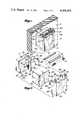
- FIG. 1is a front isometric view of the flip cover or switch guard and position indicator mechanism in place with an associated push-button switch in its released position.
- FIG. 2is an exploded isometric illustrating the flip cover mechanism together with portions of an associated push-to-actuate and push-to-release switch assembly and mounting panel.
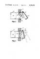
- FIGS. 3, 4, 5, and 6are longitudinal vertical sectional views respectively showing the flip cover: (3) with the push-button switch in released position; (4) with the flip cover raised and an operator's finger applied to initiate switch actuation from release position; (5) with the push-button switch in actuated, latched (swich actuated) position and the flip cover positioned correspondingly to flag the fact; and, (6) with the operator's finger shown applied to the flip cover to press the push-button head inwardly into latch-releasing position in which, when that position is reached, cooperating flip cover abutments and push-button head abutments in sliding engagement with each other will slip past each other so as to permit the push-button head to spring back into its switch-released position (FIG. 3).
- the drawingsdo not attempt to depict the conventional or otherwise suitable details of the push-button switch assembly 10 and how its tubular support casing 12 is secured in place in a framing aperture in mounting panel P.
- the switch assembly's push-button head 14 slidably received in casing 12has a forwardmost switch-released position (FIG. 3), an intermediate latched, switch-actuated position (FIG. 5) and in innermost alternatingly and transitory latch-engaging and latch-releasing position.
- the push-button headis pressed inwardly into this latter (innermost) position manually in order to trigger the scale-of-two automatic latching mechanism when the switch is to be latched (actuated) or unlatched (released).
- push-button head 14has one or more indicator indicia windows 14c internally lamp-illuminated by switch terminal contact with the switch in its actuated position (FIG. 4).
- switch details and lamp detailsare or may be conventional, so are omitted from the drawing.
- a component central to this inventionis the flip cover 16 that serves as a switch guard and position indicator.
- Thisis shown comprising a flat transparent resilient synthetic plastic plate 18 flanged inwardly (i.e. toward the mounting panel P) at its edges by a bottom flange 18a and opposite side flanges 18b and 18c all molded integrally with the plate.
- the respective side flangeshave upward extension ears 18b1 and 18c1 with mutually transversely aligned holes 18d and 18e into and through which the opposite ends of a pivot shaft 20 can be snapped and retained by forced spreading of the ears to accomodate the intermediate length of the shaft between them.
- a tubular sleeve 22Between ears 18b1 and 18c1 shaft 20 is surrounded by a tubular sleeve 22 and that in turn by a helical spring 24 having one end received in a small aperture 18f in ear 18b1.
- the opposite end of the springis lodged in a small aperture 28a in one side plate 28b of a resilient sheet metal flip cover support yoke 26.
- Side plate 28b and a similar opposite side plate 28care maintained in spaced parallel relationship by a connecting bridging plate 28d.
- the inner upright edges of side plates 28b and 28chave elongated upright flanges 28e and 28f projecting toward each other in a common tranverse plane. These flanges have respective narrow downward extension fingers 28g and 28h which can be sprung apart.
- Spring 24yieldably urges hinged guard/indicator 16 downwardly toward its normal or retracted position, a position which it occupies with the push-button head 14 in the switch-released (unlatched) position (FIGS. 1 and 3).
- cover side flanges 18b and 18chave inwardly directed mutually parallel extensions 18b2 and 18c2. These respectively carry sliding contact abutments 18b3 and 18c3 that project in mutual alignment toward each other and have transversly convexly rounded tops. The spacing between the abutments 18b3 and 18c3 slightly exceeds the outside width of the parallel sided push-button head 14.
- push-button head 14At its forward end push-button head 14 has transverse side flanges 14a and 14b the forward faces of which serve as abutments slidably engageable by the respective abutments 18b3 and 18c 3 with the cover 16 and push-button head 14 in certain relative positions (e.g., FIGS. 5 and 6).
- the abutments 18b3 and 18c3When the push-button head is in its released position, the abutments 18b3 and 18c3 having previously slipped past the upper ends of abutment flanges 14a and 14b as later explained, the flip cover 16 is maintained by its return spring 24 in the flip cover's closed or normal position (FIGS. 1 and 3).
- abutment flanges 14a and 14bare so located inwardly and downwardly relative to the flip cover pivot shaft 20 that inward/downward swinging of the flip cover to the point it is pressing the push-button head 14 into its innermost (latch-releasing) position (FIG. 6) allows the cover to snap into its fully closed rest position shown in FIG. 3.
- the lower extremeties of the abutment flanges 14a and 14bare so located as to allow the abutments 18b3 and 18c3 to flip forwardly past them when the flip cover 16 is being raised forwardly and upwardly from its closed position (FIG. 3) into a position (FIG. 4) affording access to the push-button head 14 for actuation of the switch.
- each abutment flangei.e., the distance between its positionally defined extremeties described above
- the vertical length of each abutment flangeprovides a bearing contact surface for abutments 18b3 and 18c3 which holds the flip cover 16 in outwardly inclined indicating position with the switch in its actuated (latched) position (FIG. 5).
- Flip cover 16therefore, serves to protectively cover and guard the push-button switch against accidental actuation by inadvertent leaning or pressing against the push-button head 14. It also functions as a mechanical indicator signalling switch position to the operator, such as an aircraft pilot, copilot, or navigator who may not have a face-on view of the push-button head or who may have such a view but may fail to note its position because its internal indicating lamp is burned out. Transparency of the flip cover panel permits any illuminated indicia appearing on the face of the push-button head to be seen through the flip cover either in the released position of the switch (FIG. 3) or in its actuated position (FIG. 5).
Landscapes
- Push-Button Switches (AREA)
Abstract
Description
Claims (8)
Priority Applications (1)
| Application Number | Priority Date | Filing Date | Title |
|---|---|---|---|
| US06/325,139US4394552A (en) | 1981-11-27 | 1981-11-27 | Flip-action guard and position indicator for push-to-actuate and push-to-release switch |
Applications Claiming Priority (1)
| Application Number | Priority Date | Filing Date | Title |
|---|---|---|---|
| US06/325,139US4394552A (en) | 1981-11-27 | 1981-11-27 | Flip-action guard and position indicator for push-to-actuate and push-to-release switch |
Publications (1)
| Publication Number | Publication Date |
|---|---|
| US4394552Atrue US4394552A (en) | 1983-07-19 |
Family
ID=23266598
Family Applications (1)
| Application Number | Title | Priority Date | Filing Date |
|---|---|---|---|
| US06/325,139Expired - LifetimeUS4394552A (en) | 1981-11-27 | 1981-11-27 | Flip-action guard and position indicator for push-to-actuate and push-to-release switch |
Country Status (1)
| Country | Link |
|---|---|
| US (1) | US4394552A (en) |
Cited By (24)
| Publication number | Priority date | Publication date | Assignee | Title |
|---|---|---|---|---|
| US4595228A (en)* | 1984-04-30 | 1986-06-17 | Prince Corporation | Garage door opening transmitter compartment |
| DE8710641U1 (en)* | 1987-08-04 | 1987-09-24 | Hebbel, Dierk, 7151 Allmersbach | Cover for a keyboard |
| US5144323A (en)* | 1991-05-22 | 1992-09-01 | Tendler Technologies, Inc. | Protected switch for emergency location system |
| US5723833A (en)* | 1996-07-05 | 1998-03-03 | Ryobi North America, Inc. | On-off switch within a lockable housing |
| US5807077A (en)* | 1996-12-05 | 1998-09-15 | Lamanna; Joe | Foot operated pump guard |
| US20030109244A1 (en)* | 1996-02-28 | 2003-06-12 | Tendler Robert K. | Location based service request system |
| US20040016629A1 (en)* | 2002-02-19 | 2004-01-29 | Alexander Galea | Operating switch for a motor vehicle with a movable protective device |
| US20060278504A1 (en)* | 2005-05-27 | 2006-12-14 | Michael Brojanac | Mountable lockout device |
| US20070261944A1 (en)* | 2006-05-12 | 2007-11-15 | Matsushita Electric Works, Ltd. | Operating switch mechanism |
| US7305243B1 (en) | 1996-02-28 | 2007-12-04 | Tendler Cellular, Inc. | Location based information system |
| US8197633B2 (en) | 2005-09-30 | 2012-06-12 | Covidien Ag | Method for manufacturing an end effector assembly |
| USD680220S1 (en) | 2012-01-12 | 2013-04-16 | Coviden IP | Slider handle for laparoscopic device |
| US8454602B2 (en) | 2009-05-07 | 2013-06-04 | Covidien Lp | Apparatus, system, and method for performing an electrosurgical procedure |
| US8523898B2 (en) | 2009-07-08 | 2013-09-03 | Covidien Lp | Endoscopic electrosurgical jaws with offset knife |
| US8568444B2 (en) | 2008-10-03 | 2013-10-29 | Covidien Lp | Method of transferring rotational motion in an articulating surgical instrument |
| US8591506B2 (en) | 1998-10-23 | 2013-11-26 | Covidien Ag | Vessel sealing system |
| US8597296B2 (en) | 2003-11-17 | 2013-12-03 | Covidien Ag | Bipolar forceps having monopolar extension |
| US8852228B2 (en) | 2009-01-13 | 2014-10-07 | Covidien Lp | Apparatus, system, and method for performing an electrosurgical procedure |
| US8898888B2 (en) | 2009-09-28 | 2014-12-02 | Covidien Lp | System for manufacturing electrosurgical seal plates |
| US9028493B2 (en) | 2009-09-18 | 2015-05-12 | Covidien Lp | In vivo attachable and detachable end effector assembly and laparoscopic surgical instrument and methods therefor |
| US9113940B2 (en) | 2011-01-14 | 2015-08-25 | Covidien Lp | Trigger lockout and kickback mechanism for surgical instruments |
| US10251696B2 (en) | 2001-04-06 | 2019-04-09 | Covidien Ag | Vessel sealer and divider with stop members |
| US10987159B2 (en) | 2015-08-26 | 2021-04-27 | Covidien Lp | Electrosurgical end effector assemblies and electrosurgical forceps configured to reduce thermal spread |
| US20240075907A1 (en)* | 2022-09-01 | 2024-03-07 | William Fisher | Vehicle Jacking Assembly |
Citations (2)
| Publication number | Priority date | Publication date | Assignee | Title |
|---|---|---|---|---|
| US1746724A (en)* | 1927-12-30 | 1930-02-11 | Wexberg Ernest | Semaphore signal for electric switches |
| US1884000A (en)* | 1928-05-03 | 1932-10-25 | M J Lewis Products Company | Service box |
- 1981
- 1981-11-27USUS06/325,139patent/US4394552A/ennot_activeExpired - Lifetime
Patent Citations (2)
| Publication number | Priority date | Publication date | Assignee | Title |
|---|---|---|---|---|
| US1746724A (en)* | 1927-12-30 | 1930-02-11 | Wexberg Ernest | Semaphore signal for electric switches |
| US1884000A (en)* | 1928-05-03 | 1932-10-25 | M J Lewis Products Company | Service box |
Cited By (43)
| Publication number | Priority date | Publication date | Assignee | Title |
|---|---|---|---|---|
| US4595228A (en)* | 1984-04-30 | 1986-06-17 | Prince Corporation | Garage door opening transmitter compartment |
| DE8710641U1 (en)* | 1987-08-04 | 1987-09-24 | Hebbel, Dierk, 7151 Allmersbach | Cover for a keyboard |
| US5144323A (en)* | 1991-05-22 | 1992-09-01 | Tendler Technologies, Inc. | Protected switch for emergency location system |
| US7844282B1 (en) | 1996-02-28 | 2010-11-30 | Tendler Robert K | Location based information system |
| US20030109244A1 (en)* | 1996-02-28 | 2003-06-12 | Tendler Robert K. | Location based service request system |
| US7447508B1 (en) | 1996-02-28 | 2008-11-04 | Tendler Cellular, Inc. | Location based information system |
| US7305243B1 (en) | 1996-02-28 | 2007-12-04 | Tendler Cellular, Inc. | Location based information system |
| US7050818B2 (en) | 1996-02-28 | 2006-05-23 | Tendler Cellular, Inc. | Location based service request system |
| US5723833A (en)* | 1996-07-05 | 1998-03-03 | Ryobi North America, Inc. | On-off switch within a lockable housing |
| US5807077A (en)* | 1996-12-05 | 1998-09-15 | Lamanna; Joe | Foot operated pump guard |
| US8591506B2 (en) | 1998-10-23 | 2013-11-26 | Covidien Ag | Vessel sealing system |
| US9375271B2 (en) | 1998-10-23 | 2016-06-28 | Covidien Ag | Vessel sealing system |
| US9463067B2 (en) | 1998-10-23 | 2016-10-11 | Covidien Ag | Vessel sealing system |
| US9375270B2 (en) | 1998-10-23 | 2016-06-28 | Covidien Ag | Vessel sealing system |
| US10687887B2 (en) | 2001-04-06 | 2020-06-23 | Covidien Ag | Vessel sealer and divider |
| US10265121B2 (en) | 2001-04-06 | 2019-04-23 | Covidien Ag | Vessel sealer and divider |
| US10251696B2 (en) | 2001-04-06 | 2019-04-09 | Covidien Ag | Vessel sealer and divider with stop members |
| US20040016629A1 (en)* | 2002-02-19 | 2004-01-29 | Alexander Galea | Operating switch for a motor vehicle with a movable protective device |
| US6914205B2 (en) | 2002-02-19 | 2005-07-05 | Methode Electronics Malta Ltd. | Operating switch for a motor vehicle with a movable protective device |
| US10441350B2 (en) | 2003-11-17 | 2019-10-15 | Covidien Ag | Bipolar forceps having monopolar extension |
| US8597296B2 (en) | 2003-11-17 | 2013-12-03 | Covidien Ag | Bipolar forceps having monopolar extension |
| US7348504B2 (en)* | 2005-05-27 | 2008-03-25 | Master Lock Company Llc | Mountable lockout device |
| US20060278504A1 (en)* | 2005-05-27 | 2006-12-14 | Michael Brojanac | Mountable lockout device |
| US8197633B2 (en) | 2005-09-30 | 2012-06-12 | Covidien Ag | Method for manufacturing an end effector assembly |
| US20070261944A1 (en)* | 2006-05-12 | 2007-11-15 | Matsushita Electric Works, Ltd. | Operating switch mechanism |
| US7465895B2 (en)* | 2006-05-12 | 2008-12-16 | Matsushita Electric Works, Ltd. | Operating switch mechanism |
| US8568444B2 (en) | 2008-10-03 | 2013-10-29 | Covidien Lp | Method of transferring rotational motion in an articulating surgical instrument |
| US8852228B2 (en) | 2009-01-13 | 2014-10-07 | Covidien Lp | Apparatus, system, and method for performing an electrosurgical procedure |
| US9655674B2 (en) | 2009-01-13 | 2017-05-23 | Covidien Lp | Apparatus, system and method for performing an electrosurgical procedure |
| US10085794B2 (en) | 2009-05-07 | 2018-10-02 | Covidien Lp | Apparatus, system and method for performing an electrosurgical procedure |
| US8454602B2 (en) | 2009-05-07 | 2013-06-04 | Covidien Lp | Apparatus, system, and method for performing an electrosurgical procedure |
| US9345535B2 (en) | 2009-05-07 | 2016-05-24 | Covidien Lp | Apparatus, system and method for performing an electrosurgical procedure |
| US8858554B2 (en) | 2009-05-07 | 2014-10-14 | Covidien Lp | Apparatus, system, and method for performing an electrosurgical procedure |
| US8523898B2 (en) | 2009-07-08 | 2013-09-03 | Covidien Lp | Endoscopic electrosurgical jaws with offset knife |
| US9931131B2 (en) | 2009-09-18 | 2018-04-03 | Covidien Lp | In vivo attachable and detachable end effector assembly and laparoscopic surgical instrument and methods therefor |
| US9028493B2 (en) | 2009-09-18 | 2015-05-12 | Covidien Lp | In vivo attachable and detachable end effector assembly and laparoscopic surgical instrument and methods therefor |
| US8898888B2 (en) | 2009-09-28 | 2014-12-02 | Covidien Lp | System for manufacturing electrosurgical seal plates |
| US9113940B2 (en) | 2011-01-14 | 2015-08-25 | Covidien Lp | Trigger lockout and kickback mechanism for surgical instruments |
| US10383649B2 (en) | 2011-01-14 | 2019-08-20 | Covidien Lp | Trigger lockout and kickback mechanism for surgical instruments |
| US11660108B2 (en) | 2011-01-14 | 2023-05-30 | Covidien Lp | Trigger lockout and kickback mechanism for surgical instruments |
| USD680220S1 (en) | 2012-01-12 | 2013-04-16 | Coviden IP | Slider handle for laparoscopic device |
| US10987159B2 (en) | 2015-08-26 | 2021-04-27 | Covidien Lp | Electrosurgical end effector assemblies and electrosurgical forceps configured to reduce thermal spread |
| US20240075907A1 (en)* | 2022-09-01 | 2024-03-07 | William Fisher | Vehicle Jacking Assembly |
Similar Documents
| Publication | Publication Date | Title |
|---|---|---|
| US4394552A (en) | Flip-action guard and position indicator for push-to-actuate and push-to-release switch | |
| US5440814A (en) | Knife with side guards | |
| US5862596A (en) | Hand held cutter | |
| US6357534B1 (en) | Battery pack latching assembly for fastener driving tool | |
| US4363016A (en) | Circuit breaker | |
| KR960704421A (en) | Telephone Mounting Receptacle Having Opposed Retractable Latch Members | |
| KR940001979Y1 (en) | Protective plate attachment structure in helmet | |
| GB2083538A (en) | Vanity case | |
| US4023388A (en) | Lock cover device | |
| EP1158752B1 (en) | Radiotelephone | |
| US4354077A (en) | Push-button panel assembly including an individually lighted push-button switch assembly | |
| GB1340444A (en) | Push button switch with a switch position indicating means | |
| US5610375A (en) | Circuit breaker with pivoting control buttons | |
| US4549778A (en) | Electrical socket cover | |
| CA1242236A (en) | Toggle switch remote operator | |
| US4139756A (en) | Push button switch with secondary push button | |
| US1775768A (en) | Wall-lamp attachment | |
| US4031849A (en) | Push button switch position indicator | |
| US3280321A (en) | Door handle light for automobiles | |
| US4129766A (en) | Indicating mechanism for push button switches | |
| GB2255232A (en) | Alarm call points | |
| JP6604642B1 (en) | Adapter for slide operation conversion of rocker switch. | |
| US4547054A (en) | Finger over the lens detecting apparatus | |
| US5359755A (en) | Garment security clip | |
| KR200368411Y1 (en) | Safety Device for Door |
Legal Events
| Date | Code | Title | Description |
|---|---|---|---|
| AS | Assignment | Owner name:KORRY MANUFACTURING CO., 223 8TH AVE N., SEATTLE, Free format text:ASSIGNMENT OF ASSIGNORS INTEREST.;ASSIGNOR:SCHLOSSER, MARK S.;REEL/FRAME:003962/0409 Effective date:19811118 | |
| STCF | Information on status: patent grant | Free format text:PATENTED CASE | |
| MAFP | Maintenance fee payment | Free format text:PAYMENT OF MAINTENANCE FEE, 4TH YEAR, PL 96-517 (ORIGINAL EVENT CODE: M170); ENTITY STATUS OF PATENT OWNER: LARGE ENTITY Year of fee payment:4 | |
| AS | Assignment | Owner name:KORRY ELECTRONICS, INC. Free format text:CHANGE OF NAME;ASSIGNOR:KORRY MANUFACTURING CO.;REEL/FRAME:005007/0707 Effective date:19820928 | |
| AS | Assignment | Owner name:CRITON TECHNOLOGIES, A NEW YORK GENERAL PARTNERSHI Free format text:ASSIGNMENT OF ASSIGNORS INTEREST.;ASSIGNOR:KORRY ELECTRONICS, INC.;REEL/FRAME:005010/0230 Effective date:19890109 | |
| AS | Assignment | Owner name:CRITON TECHNOLOGIES, A WA CORP., WASHINGTON Free format text:ASSIGNMENT OF ASSIGNORS INTEREST.;ASSIGNOR:CRITON TECHNOLOGIES;REEL/FRAME:005195/0134 Effective date:19891127 | |
| MAFP | Maintenance fee payment | Free format text:PAYMENT OF MAINTENANCE FEE, 8TH YEAR, PL 96-517 (ORIGINAL EVENT CODE: M171); ENTITY STATUS OF PATENT OWNER: LARGE ENTITY Year of fee payment:8 | |
| AS | Assignment | Owner name:CONTINENTAL BANK N.A., AS AGENT, ILLINOIS Free format text:SECURITY INTEREST;ASSIGNOR:KORRY ELECTRONICS CO.;REEL/FRAME:005659/0187 Effective date:19910217 | |
| AS | Assignment | Owner name:KORRY ELECTRONICS CO., WASHINGTON Free format text:RELEASED BY SECURED PARTY;ASSIGNOR:CONTINENTAL BANK N.A.;REEL/FRAME:006290/0277 Effective date:19921015 | |
| MAFP | Maintenance fee payment | Free format text:PAYMENT OF MAINTENANCE FEE, 12TH YEAR, LARGE ENTITY (ORIGINAL EVENT CODE: M185); ENTITY STATUS OF PATENT OWNER: LARGE ENTITY Year of fee payment:12 | |
| FEPP | Fee payment procedure | Free format text:PAYOR NUMBER ASSIGNED (ORIGINAL EVENT CODE: ASPN); ENTITY STATUS OF PATENT OWNER: LARGE ENTITY |