US4393752A - Piston compressor - Google Patents
Piston compressorDownload PDFInfo
- Publication number
- US4393752A US4393752AUS06/232,975US23297581AUS4393752AUS 4393752 AUS4393752 AUS 4393752AUS 23297581 AUS23297581 AUS 23297581AUS 4393752 AUS4393752 AUS 4393752A
- Authority
- US
- United States
- Prior art keywords
- wall
- cylinder liner
- cylinder
- cylinder block
- coolant
- Prior art date
- Legal status (The legal status is an assumption and is not a legal conclusion. Google has not performed a legal analysis and makes no representation as to the accuracy of the status listed.)
- Expired - Lifetime
Links
- 239000002826coolantSubstances0.000claimsabstractdescription42
- 239000007789gasSubstances0.000claimsabstractdescription26
- 230000006835compressionEffects0.000claimsabstractdescription13
- 238000007906compressionMethods0.000claimsabstractdescription13
- 230000008719thickeningEffects0.000claimsdescription10
- 239000011261inert gasSubstances0.000claimsdescription3
- 239000007788liquidSubstances0.000claims1
- 239000000498cooling waterSubstances0.000abstractdescription8
- 238000001816coolingMethods0.000abstractdescription7
- QVGXLLKOCUKJST-UHFFFAOYSA-Natomic oxygenChemical compound[O]QVGXLLKOCUKJST-UHFFFAOYSA-N0.000description7
- 239000001301oxygenSubstances0.000description7
- 229910052760oxygenInorganic materials0.000description7
- XLYOFNOQVPJJNP-UHFFFAOYSA-NwaterSubstancesOXLYOFNOQVPJJNP-UHFFFAOYSA-N0.000description6
- 230000007797corrosionEffects0.000description5
- 238000005260corrosionMethods0.000description5
- IJGRMHOSHXDMSA-UHFFFAOYSA-NAtomic nitrogenChemical compoundN#NIJGRMHOSHXDMSA-UHFFFAOYSA-N0.000description4
- 230000002950deficientEffects0.000description2
- 238000002844meltingMethods0.000description2
- 230000008018meltingEffects0.000description2
- 229910052757nitrogenInorganic materials0.000description2
- 238000012856packingMethods0.000description2
- 238000003466weldingMethods0.000description2
- ZAMOUSCENKQFHK-UHFFFAOYSA-NChlorine atomChemical compound[Cl]ZAMOUSCENKQFHK-UHFFFAOYSA-N0.000description1
- MYMOFIZGZYHOMD-UHFFFAOYSA-NDioxygenChemical compoundO=OMYMOFIZGZYHOMD-UHFFFAOYSA-N0.000description1
- 239000000460chlorineSubstances0.000description1
- 229910052801chlorineInorganic materials0.000description1
- 238000010276constructionMethods0.000description1
- 230000000694effectsEffects0.000description1
- 230000002349favourable effectEffects0.000description1
- 230000007704transitionEffects0.000description1
Images

Classifications
- F—MECHANICAL ENGINEERING; LIGHTING; HEATING; WEAPONS; BLASTING
- F04—POSITIVE - DISPLACEMENT MACHINES FOR LIQUIDS; PUMPS FOR LIQUIDS OR ELASTIC FLUIDS
- F04B—POSITIVE-DISPLACEMENT MACHINES FOR LIQUIDS; PUMPS
- F04B39/00—Component parts, details, or accessories, of pumps or pumping systems specially adapted for elastic fluids, not otherwise provided for in, or of interest apart from, groups F04B25/00 - F04B37/00
- F04B39/12—Casings; Cylinders; Cylinder heads; Fluid connections
- F04B39/126—Cylinder liners
- F—MECHANICAL ENGINEERING; LIGHTING; HEATING; WEAPONS; BLASTING
- F04—POSITIVE - DISPLACEMENT MACHINES FOR LIQUIDS; PUMPS FOR LIQUIDS OR ELASTIC FLUIDS
- F04B—POSITIVE-DISPLACEMENT MACHINES FOR LIQUIDS; PUMPS
- F04B39/00—Component parts, details, or accessories, of pumps or pumping systems specially adapted for elastic fluids, not otherwise provided for in, or of interest apart from, groups F04B25/00 - F04B37/00
- F04B39/06—Cooling; Heating; Prevention of freezing
- F04B39/064—Cooling by a cooling jacket in the pump casing
- F—MECHANICAL ENGINEERING; LIGHTING; HEATING; WEAPONS; BLASTING
- F16—ENGINEERING ELEMENTS AND UNITS; GENERAL MEASURES FOR PRODUCING AND MAINTAINING EFFECTIVE FUNCTIONING OF MACHINES OR INSTALLATIONS; THERMAL INSULATION IN GENERAL
- F16J—PISTONS; CYLINDERS; SEALINGS
- F16J10/00—Engine or like cylinders; Features of hollow, e.g. cylindrical, bodies in general
- F16J10/02—Cylinders designed to receive moving pistons or plungers
- F16J10/04—Running faces; Liners
- Y—GENERAL TAGGING OF NEW TECHNOLOGICAL DEVELOPMENTS; GENERAL TAGGING OF CROSS-SECTIONAL TECHNOLOGIES SPANNING OVER SEVERAL SECTIONS OF THE IPC; TECHNICAL SUBJECTS COVERED BY FORMER USPC CROSS-REFERENCE ART COLLECTIONS [XRACs] AND DIGESTS
- Y10—TECHNICAL SUBJECTS COVERED BY FORMER USPC
- Y10S—TECHNICAL SUBJECTS COVERED BY FORMER USPC CROSS-REFERENCE ART COLLECTIONS [XRACs] AND DIGESTS
- Y10S417/00—Pumps
- Y10S417/901—Cryogenic pumps
Definitions
- This inventionrelates to a piston compressor. More particularly, this invention relates to a piston compressor for compressing combustible or fire-causing gases such as oxygen.
- piston compressorsfor compressing combustible or fire-causing gases such as oxygen.
- such compressorshave been constructed of a water cooled cylinder block which has at least one cylinder liner sealingly mounted within the block and in which a single-action piston reciprocates.
- a collecting chamberis usually provided for leakage gas at the end of the cylinder liner remote from a compression chamber formed within the cylinder block.
- cooling water contained in the cylinder blockwets the outer surface of the cylinder liner. For this reason, a seal is usually provided between the cylinder block wall and the cylinder liner near the lower end of the cylinder liner.
- this sealconstitutes a problem where the piston compressor has a leakage gas collecting chamber as the seal may become defective due to water-side corrosion.
- further corrosioncan occur on the cylinder liner as well as on the cylinder block. This, in turn, would greatly reduce the life of the compressor.
- the inventionprovides a piston compressor which is constructed with a cylinder block, a double walled cylinder liner mounted in the cylinder block and a collecting chamber in the cylinder block for receiving leakage gas.
- the cylinder lineris constructed with a first wall which defines a bore for reciprocation of a piston therein and a second wall annularly spaced from the first wall in order to define an annular chamber therebetween for receiving a coolant.
- this second wallis spaced from a wall of the cylinder block in order to define an annular space therebetween.
- the collecting chamberis disposed in communication with the bore of the cylinder liner to receive leakage gas.
- the coolant within the annular chambermay be passed therethrough in a forced-flow manner so as to effect a forced cooling.
- the annular space between the liner and the cylinder blockseparates the liner from any cooling water which is contained in the cylinder block. This annular space starts from a seal located between one end of the cylinder liner and the cylinder block and extends to an opposite end of the liner.
- the forced cooling of the double walled cylinderensures proper removal of the heat of compression and is adapted to the operating conditions despite the presence of the annular space.
- the annular space and the cooling water contained in the cylinder blockprovide good fire protection for the compressor and the surrounding environment should a fire break out in the compression chamber.
- the cylinder linermay melt through, the cylinder block would not undergo major damage as the annular space would interrupt continued melting. The damage done by such melting may be remedied relatively quickly and at relatively low cost by replacing the cylinder liner rather than replacing or repairing a cylinder block.
- the cooling water contained in the cylinder blockalso helps to maintain the dimensions of the cylinder block essentially constant. This is especially favorable when several cylinders are disposed in the same cylinder block.
- a pair of spiralsare disposed between the walls of the cylinder liner to define a helical inflow passage for coolant and a helical outflow passage for the coolant.
- a coolant inletconnects with the inflow passage while a coolant outlet connects with the outflow passage.
- a pair of parallel tubesare disposed between the walls of the cylinder liner in diametric relation.
- Each tubeis provided with a plurality of longitudinally spaced apertures while a coolant inlet connects to one tube and a coolant outlet connects to the other tube.
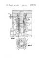
- FIG. 1illustrates an axial sectional view through a cylinder block of a piston compressor according to the invention
- FIG. 2illustrates a view taken on line II--II of FIG. 1;
- FIG. 3illustrates an axial sectional view through a modified cylinder block constructed in accordance with the invention.
- FIG. 4illustrates a view taken on line IV--IV of FIG. 3.
- a cylinder block 1 of a piston compressorfor example, for compressing oxygen, is provided with at least one cylinder liner 2.
- the cylinder liner 2is formed of double walled construction and cooperates with a reciprocal piston 3 and a recess in a cover 5 of the cylinder block to define a compression chamber 4.
- the piston 3is provided with labyrinth packings (not shown) to reciprocate, i.e. move up and down as viewed, within the liner 2 without making contact while compression of the oxygen takes place in the compression chamber 4 during upward movement of the piston 3.
- Inlet and outlet valves to the compression chamberare not shown for simplicity.
- a collecting chamber 6is disposed in the cylinder block for receiving leakage gas. Because of the contactless movement of the piston 3 in the liner 2, during each upward stroke, some gas escapes along the piston 3 and collects as leakage gas in the chamber 6. The leakage gas can be returned from the collecting chamber 6 via a line (not shown) to the suction side of the compressor. As indicated in FIG. 1, a recess 7 in the cylinder block 1 below the cylinder liner 2 can be provided with a seal (not shown) for a piston rod connected to the piston 3 in order to prevent leakage gas from entering the crank space of the compressor.
- the cylinder liner 2has a first wall which defines a bore for reciprocation of the piston therein in spaced annular relation.
- the liner 2has a second wall 8 annularly spaced from the first wall in order to define an annular chamber 9 therebetween.
- the second wall 8is formed by a sleeve which is sealingly connected such as by welding at each end to a flange-type thickening 19, 19' at the respective ends of the liner 2.
- a pair of helical spiralsis located between the walls of the cylinder liner 2 in order to define a helical inflow passage for coolant and a helical outflow passage for the coolant.
- the spirals 10are integral with the inner wall of the liner and abut the sleeve 8.
- Suitable meansare provided for passing a coolant through the helical passages within the liner 2.
- two radial dividing walls 11, 12are welded into the chamber 9 above the two spirals 10 so that a coolant inlet chamber 13 and a coolant outlet chamber 14 are formed for the coolant.
- a coolant inletcommunicates the inlet chamber 13 with a coolant feed line 15 (see FIG. 2), while a coolant outlet communicates the chamber 14 with a coolant discharge line 16 (see FIG. 2).
- each of the lines 15, 16is secured in the flange-like thickening 19' of the cylinder liner 2.
- a coolantsuch as water
- the coolant streamis conducted upwardly through the other helical passage.
- the lower end of the cylinder liner 2extends through a bore 17 of the cylinder block 1 into the collecting chamber 6.
- a seal ring 20is inserted at the transition to the lower flange-type thickening 19 of the liner 2. This seal ring 20 is pressed by liner 2 against the cylinder block 1 as the cylinder cover 5 is being clamped on to the cylinder block 1.
- a seal ring 18is provided in the thickening 19' to seal against the cover 5.
- the wall 8is spaced from a wall 22 of the cylinder block 1 to define an annular space 21 therebetween.
- This annular spaceextends from above the seal ring 20 to the upper thickening 19' and is connected with a vent line 24 in the cylinder block 1.
- the cylinder block 1is also provided with a space 23 through which cooling water may flow.
- compressed oxygenis discharged from the compression chamber 4 via a pressure line (not shown) in the cylinder cover 5.
- Leakage gas flowing along the piston 3 out of the compression chamber 4collects in the chamber 6.
- the oxygencannot come in contact with the cooling water in the space 23 in the cylinder block or the water in the chamber 9 within the liner 2 due to the presence of the air filled space 21.
- the forced cooling in the chamber 9 of the cylinder liner 2provides sufficient cooling of the liner 2.
- the cylinder liner 2may be force cooled in another manner.
- a pair of parallel tubes 30, 31are located between the walls of the cylinder liner 2 in diametric relation and in parallel to the axis of the liner.
- Each of these tubes 30, 31has a plurality of longitudinally spaced apertures or slots 32 therein which serve for the passage of coolant.
- a coolant supply line 33is threaded into the upper thickening 19' to communicate with the upper of one tube 30 while a similar coolant discharge line 34 is threaded into the thickening 19' to communicate with the outlet end of the other tube 31.
- Each of these lines 33, 34serves as an inlet or outlet for the respective tubes 30, 31.
- a leakage gas collecting chamber 6is provided in the zone of the lower end of the cylinder liner 2 through which the piston 3 extends.
- a pressure gauge 35can be connected to the vent line 24 so that the air pressure in the space 21 can be monitored.
- the pressure gaugecould be in active connection with a drive motor of the compressor so that at a pressure which deviates from the normal pressure in the space 21, the drive motor could be automatically stopped. This would be especially useful upon occurrence of a fire in the cylinder chamber.
- a relief devicemay be connected to the compression chamber 4 in order to be actuated as a function of the pressure in the space 21.
- the space 21may be filled with an inert gas such as nitrogen so that the operation of the packings can be monitored, for example by a control of the nitrogen pressure and/or composition of the gas in the space 21.
- an inert gassuch as nitrogen
- coolant supply lines 15, 33may be provided with valves so as to adapt the quantities of coolant traversing the chamber 9 to the operating conditions of the compressor.
- spirals 10may be separate structural parts which can be welded or otherwise secured to the liner walls or may be formed by buildup welding.
- the fire causing gas which is compressed in the compressormay also be of other types than oxygen e.g. chlorine.
- coolant in the chamber 9 and the space 23may come from the same source, may be of the same kind but of different quality or grade, or may be of different kind.
- the inventionthus provides a piston compressor wherein leakage of gas into the coolant passageways or chambers of the compressor are avoided.
Landscapes
- Engineering & Computer Science (AREA)
- General Engineering & Computer Science (AREA)
- Mechanical Engineering (AREA)
- Chemical & Material Sciences (AREA)
- Combustion & Propulsion (AREA)
- Compressor (AREA)
- Compressors, Vaccum Pumps And Other Relevant Systems (AREA)
Abstract
Description
Claims (11)
Applications Claiming Priority (2)
| Application Number | Priority Date | Filing Date | Title |
|---|---|---|---|
| CH120980ACH641876A5 (en) | 1980-02-14 | 1980-02-14 | PISTON COMPRESSOR, IN PARTICULAR TO COMPRESS OXYGEN. |
| CH1209/80 | 1980-02-14 |
Publications (1)
| Publication Number | Publication Date |
|---|---|
| US4393752Atrue US4393752A (en) | 1983-07-19 |
Family
ID=4205055
Family Applications (1)
| Application Number | Title | Priority Date | Filing Date |
|---|---|---|---|
| US06/232,975Expired - LifetimeUS4393752A (en) | 1980-02-14 | 1981-02-09 | Piston compressor |
Country Status (7)
| Country | Link |
|---|---|
| US (1) | US4393752A (en) |
| CH (1) | CH641876A5 (en) |
| DE (1) | DE3006332C2 (en) |
| FR (1) | FR2476236A1 (en) |
| GB (1) | GB2071269B (en) |
| IT (1) | IT1135363B (en) |
| NL (1) | NL8100430A (en) |
Cited By (46)
| Publication number | Priority date | Publication date | Assignee | Title |
|---|---|---|---|---|
| US4576557A (en)* | 1983-06-15 | 1986-03-18 | Union Carbide Corporation | Cryogenic liquid pump |
| US4792289A (en)* | 1986-06-28 | 1988-12-20 | Deutsche Forschungs- Und Versuchsanstalt Fur Luft- Und Raumfahrt E.V. | Reciprocating pump for cryogenic fluids |
| US5549454A (en)* | 1993-03-04 | 1996-08-27 | Wabco Automotive U.K. Limited | High speed vacuum pump with reduced exhaust noise |
| EP0976993A3 (en)* | 1998-07-27 | 2000-03-29 | EMBRACO EUROPE S.r.l. | A motor compressor for refrigerating apparatus and refrigerating apparatus including such motor compressor |
| US20040224942A1 (en)* | 2003-01-23 | 2004-11-11 | Weiner David M. | Use of N-desmethylclozapine to treat human neuropsychiatric disease |
| US20080168898A1 (en)* | 2007-01-12 | 2008-07-17 | Hardin John W | Air compressor |
| CN101331319B (en)* | 2005-12-13 | 2010-10-20 | 克诺尔-布里姆斯轨道车辆系统有限公司 | Water-cooled piston compressor |
| US7900444B1 (en) | 2008-04-09 | 2011-03-08 | Sustainx, Inc. | Systems and methods for energy storage and recovery using compressed gas |
| US7958731B2 (en) | 2009-01-20 | 2011-06-14 | Sustainx, Inc. | Systems and methods for combined thermal and compressed gas energy conversion systems |
| US7963110B2 (en) | 2009-03-12 | 2011-06-21 | Sustainx, Inc. | Systems and methods for improving drivetrain efficiency for compressed gas energy storage |
| US8037678B2 (en) | 2009-09-11 | 2011-10-18 | Sustainx, Inc. | Energy storage and generation systems and methods using coupled cylinder assemblies |
| US8046990B2 (en) | 2009-06-04 | 2011-11-01 | Sustainx, Inc. | Systems and methods for improving drivetrain efficiency for compressed gas energy storage and recovery systems |
| US8104274B2 (en) | 2009-06-04 | 2012-01-31 | Sustainx, Inc. | Increased power in compressed-gas energy storage and recovery |
| US8117842B2 (en) | 2009-11-03 | 2012-02-21 | Sustainx, Inc. | Systems and methods for compressed-gas energy storage using coupled cylinder assemblies |
| US8171728B2 (en) | 2010-04-08 | 2012-05-08 | Sustainx, Inc. | High-efficiency liquid heat exchange in compressed-gas energy storage systems |
| US8191362B2 (en) | 2010-04-08 | 2012-06-05 | Sustainx, Inc. | Systems and methods for reducing dead volume in compressed-gas energy storage systems |
| US8225606B2 (en) | 2008-04-09 | 2012-07-24 | Sustainx, Inc. | Systems and methods for energy storage and recovery using rapid isothermal gas expansion and compression |
| US8234863B2 (en) | 2010-05-14 | 2012-08-07 | Sustainx, Inc. | Forming liquid sprays in compressed-gas energy storage systems for effective heat exchange |
| US8240140B2 (en) | 2008-04-09 | 2012-08-14 | Sustainx, Inc. | High-efficiency energy-conversion based on fluid expansion and compression |
| US8240146B1 (en) | 2008-06-09 | 2012-08-14 | Sustainx, Inc. | System and method for rapid isothermal gas expansion and compression for energy storage |
| US8250863B2 (en) | 2008-04-09 | 2012-08-28 | Sustainx, Inc. | Heat exchange with compressed gas in energy-storage systems |
| US8272212B2 (en) | 2011-11-11 | 2012-09-25 | General Compression, Inc. | Systems and methods for optimizing thermal efficiencey of a compressed air energy storage system |
| US8359856B2 (en) | 2008-04-09 | 2013-01-29 | Sustainx Inc. | Systems and methods for efficient pumping of high-pressure fluids for energy storage and recovery |
| US8448433B2 (en) | 2008-04-09 | 2013-05-28 | Sustainx, Inc. | Systems and methods for energy storage and recovery using gas expansion and compression |
| US8474255B2 (en) | 2008-04-09 | 2013-07-02 | Sustainx, Inc. | Forming liquid sprays in compressed-gas energy storage systems for effective heat exchange |
| US8479505B2 (en) | 2008-04-09 | 2013-07-09 | Sustainx, Inc. | Systems and methods for reducing dead volume in compressed-gas energy storage systems |
| US8495872B2 (en) | 2010-08-20 | 2013-07-30 | Sustainx, Inc. | Energy storage and recovery utilizing low-pressure thermal conditioning for heat exchange with high-pressure gas |
| US8522538B2 (en) | 2011-11-11 | 2013-09-03 | General Compression, Inc. | Systems and methods for compressing and/or expanding a gas utilizing a bi-directional piston and hydraulic actuator |
| US8539763B2 (en) | 2011-05-17 | 2013-09-24 | Sustainx, Inc. | Systems and methods for efficient two-phase heat transfer in compressed-air energy storage systems |
| US8567303B2 (en) | 2010-12-07 | 2013-10-29 | General Compression, Inc. | Compressor and/or expander device with rolling piston seal |
| US8572959B2 (en) | 2011-01-13 | 2013-11-05 | General Compression, Inc. | Systems, methods and devices for the management of heat removal within a compression and/or expansion device or system |
| US8578708B2 (en) | 2010-11-30 | 2013-11-12 | Sustainx, Inc. | Fluid-flow control in energy storage and recovery systems |
| US8667792B2 (en) | 2011-10-14 | 2014-03-11 | Sustainx, Inc. | Dead-volume management in compressed-gas energy storage and recovery systems |
| US8677744B2 (en) | 2008-04-09 | 2014-03-25 | SustaioX, Inc. | Fluid circulation in energy storage and recovery systems |
| DE102013002864A1 (en) | 2013-02-20 | 2014-08-21 | BORSlG Compressor Parts GmbH | Liquid-cooled, double acting, single- or multi-stage piston compressor has piston, which is axially movable in cylinder, and cooling coil, which is mounted on outer surface of cylinder liner or inner surface of cylinder cooling jacket |
| US8997475B2 (en) | 2011-01-10 | 2015-04-07 | General Compression, Inc. | Compressor and expander device with pressure vessel divider baffle and piston |
| US9109511B2 (en) | 2009-12-24 | 2015-08-18 | General Compression, Inc. | System and methods for optimizing efficiency of a hydraulically actuated system |
| US9109512B2 (en) | 2011-01-14 | 2015-08-18 | General Compression, Inc. | Compensated compressed gas storage systems |
| US20170030341A1 (en)* | 2015-07-27 | 2017-02-02 | Caterpillar Inc. | Multi-plunger cryogenic pump having intake manifold |
| US9828987B2 (en) | 2015-01-30 | 2017-11-28 | Caterpillar Inc. | System and method for priming a pump |
| US9828976B2 (en) | 2015-01-30 | 2017-11-28 | Caterpillar Inc. | Pump for cryogenic liquids having temperature managed pumping mechanism |
| US9909582B2 (en) | 2015-01-30 | 2018-03-06 | Caterpillar Inc. | Pump with plunger having tribological coating |
| US9926922B2 (en) | 2015-01-30 | 2018-03-27 | Caterpillar Inc. | Barrel assembly for a fluid pump having separate plunger bore and outlet passage |
| US10041484B2 (en) | 2015-01-30 | 2018-08-07 | Caterpillar Inc. | Pump having inlet reservoir with vapor-layer standpipe |
| US10041447B2 (en) | 2015-01-30 | 2018-08-07 | Caterpillar Inc. | Pump manifold |
| CN114439728A (en)* | 2022-02-15 | 2022-05-06 | 西安佰能达动力科技有限公司 | Circulation liquid seal compressor |
Families Citing this family (3)
| Publication number | Priority date | Publication date | Assignee | Title |
|---|---|---|---|---|
| US4930406A (en)* | 1988-09-21 | 1990-06-05 | Bristol Compressors, Inc. | Refrigerant gas compressor construction |
| DE102009011214A1 (en)* | 2009-03-04 | 2010-09-23 | Technische Universität Dresden | piston compressor |
| DE102009018213B4 (en)* | 2009-04-21 | 2015-07-09 | Oerlikon Leybold Vacuum Gmbh | vacuum pump housing |
Citations (13)
| Publication number | Priority date | Publication date | Assignee | Title |
|---|---|---|---|---|
| US1998264A (en)* | 1932-07-30 | 1935-04-16 | Westinghouse Air Brake Co | Compressor |
| US2078499A (en)* | 1928-09-01 | 1937-04-27 | Spontan Ab | Cooling system for internal combustion engines |
| US2873061A (en)* | 1953-10-13 | 1959-02-10 | Joy Mfg Co | Compressor |
| US2931313A (en)* | 1955-06-24 | 1960-04-05 | Joy Mfg Co | Pump |
| US3206110A (en)* | 1964-03-27 | 1965-09-14 | Ingersoll Rand Co | Cooling means for a compressor |
| US3263622A (en)* | 1964-06-01 | 1966-08-02 | Jr Lewis Tyree | Pump |
| US3410256A (en)* | 1965-01-12 | 1968-11-12 | Daimler Benz Ag | Internal combustion engine with liquid-cooled cylinder liners |
| US3601384A (en)* | 1969-05-09 | 1971-08-24 | Lewis H Durdin | Tuyeres |
| US3628427A (en)* | 1970-04-06 | 1971-12-21 | Caterpillar Tractor Co | Combustion gas seal |
| US3659569A (en)* | 1969-11-03 | 1972-05-02 | Maschf Augsburg Nuernberg Ag | Liquid cooled cylinder sleeve, particularly for internal combustion engines |
| US3672263A (en)* | 1969-03-28 | 1972-06-27 | Daimler Benz Ag | Cylinder block for liquid-cooled internal combustion engines with inserted cylinder liner |
| US3865015A (en)* | 1972-05-12 | 1975-02-11 | United Stirling Ab & Co | Sealing means for the piston rod of a stirling engine |
| US3972396A (en)* | 1975-06-05 | 1976-08-03 | United Technologies Corporation | Leakage detector with back pressure sensor |
Family Cites Families (5)
| Publication number | Priority date | Publication date | Assignee | Title |
|---|---|---|---|---|
| FR332224A (en)* | 1903-05-19 | 1903-10-19 | Henry Bland | Improvements in compressors |
| DE901477C (en)* | 1943-07-01 | 1954-01-11 | Daimler Benz Ag | Cylinder for liquid-cooled internal combustion engines |
| GB580889A (en)* | 1944-05-10 | 1946-09-24 | Hans Ganz | Improvements in or relating to packings between normally stationary parts for use preferably in internal combustion engines |
| DE804502C (en)* | 1949-11-20 | 1951-04-23 | Mahle Kg | Cylinders, especially for air-cooled internal combustion engines |
| DE1190959B (en)* | 1961-02-17 | 1965-04-15 | Linde Eismasch Ag | Refrigerant piston compressor with cooled cylinder wall |
- 1980
- 1980-02-14CHCH120980Apatent/CH641876A5/ennot_activeIP Right Cessation
- 1980-02-20DEDE3006332Apatent/DE3006332C2/ennot_activeExpired
- 1981
- 1981-01-29NLNL8100430Apatent/NL8100430A/ennot_activeApplication Discontinuation
- 1981-02-09USUS06/232,975patent/US4393752A/ennot_activeExpired - Lifetime
- 1981-02-09ITIT19593/81Apatent/IT1135363B/enactive
- 1981-02-13FRFR8102876Apatent/FR2476236A1/enactiveGranted
- 1981-02-16GBGB8104790Apatent/GB2071269B/ennot_activeExpired
Patent Citations (13)
| Publication number | Priority date | Publication date | Assignee | Title |
|---|---|---|---|---|
| US2078499A (en)* | 1928-09-01 | 1937-04-27 | Spontan Ab | Cooling system for internal combustion engines |
| US1998264A (en)* | 1932-07-30 | 1935-04-16 | Westinghouse Air Brake Co | Compressor |
| US2873061A (en)* | 1953-10-13 | 1959-02-10 | Joy Mfg Co | Compressor |
| US2931313A (en)* | 1955-06-24 | 1960-04-05 | Joy Mfg Co | Pump |
| US3206110A (en)* | 1964-03-27 | 1965-09-14 | Ingersoll Rand Co | Cooling means for a compressor |
| US3263622A (en)* | 1964-06-01 | 1966-08-02 | Jr Lewis Tyree | Pump |
| US3410256A (en)* | 1965-01-12 | 1968-11-12 | Daimler Benz Ag | Internal combustion engine with liquid-cooled cylinder liners |
| US3672263A (en)* | 1969-03-28 | 1972-06-27 | Daimler Benz Ag | Cylinder block for liquid-cooled internal combustion engines with inserted cylinder liner |
| US3601384A (en)* | 1969-05-09 | 1971-08-24 | Lewis H Durdin | Tuyeres |
| US3659569A (en)* | 1969-11-03 | 1972-05-02 | Maschf Augsburg Nuernberg Ag | Liquid cooled cylinder sleeve, particularly for internal combustion engines |
| US3628427A (en)* | 1970-04-06 | 1971-12-21 | Caterpillar Tractor Co | Combustion gas seal |
| US3865015A (en)* | 1972-05-12 | 1975-02-11 | United Stirling Ab & Co | Sealing means for the piston rod of a stirling engine |
| US3972396A (en)* | 1975-06-05 | 1976-08-03 | United Technologies Corporation | Leakage detector with back pressure sensor |
Cited By (66)
| Publication number | Priority date | Publication date | Assignee | Title |
|---|---|---|---|---|
| US4576557A (en)* | 1983-06-15 | 1986-03-18 | Union Carbide Corporation | Cryogenic liquid pump |
| US4792289A (en)* | 1986-06-28 | 1988-12-20 | Deutsche Forschungs- Und Versuchsanstalt Fur Luft- Und Raumfahrt E.V. | Reciprocating pump for cryogenic fluids |
| US5549454A (en)* | 1993-03-04 | 1996-08-27 | Wabco Automotive U.K. Limited | High speed vacuum pump with reduced exhaust noise |
| EP0976993A3 (en)* | 1998-07-27 | 2000-03-29 | EMBRACO EUROPE S.r.l. | A motor compressor for refrigerating apparatus and refrigerating apparatus including such motor compressor |
| US20040224942A1 (en)* | 2003-01-23 | 2004-11-11 | Weiner David M. | Use of N-desmethylclozapine to treat human neuropsychiatric disease |
| CN101331319B (en)* | 2005-12-13 | 2010-10-20 | 克诺尔-布里姆斯轨道车辆系统有限公司 | Water-cooled piston compressor |
| US20080168898A1 (en)* | 2007-01-12 | 2008-07-17 | Hardin John W | Air compressor |
| US7765917B2 (en) | 2007-01-12 | 2010-08-03 | Black & Decker Inc. | Air compressor |
| US8733094B2 (en) | 2008-04-09 | 2014-05-27 | Sustainx, Inc. | Systems and methods for energy storage and recovery using rapid isothermal gas expansion and compression |
| US8359856B2 (en) | 2008-04-09 | 2013-01-29 | Sustainx Inc. | Systems and methods for efficient pumping of high-pressure fluids for energy storage and recovery |
| US7900444B1 (en) | 2008-04-09 | 2011-03-08 | Sustainx, Inc. | Systems and methods for energy storage and recovery using compressed gas |
| US8733095B2 (en) | 2008-04-09 | 2014-05-27 | Sustainx, Inc. | Systems and methods for efficient pumping of high-pressure fluids for energy |
| US8713929B2 (en) | 2008-04-09 | 2014-05-06 | Sustainx, Inc. | Systems and methods for energy storage and recovery using compressed gas |
| US8677744B2 (en) | 2008-04-09 | 2014-03-25 | SustaioX, Inc. | Fluid circulation in energy storage and recovery systems |
| US8627658B2 (en) | 2008-04-09 | 2014-01-14 | Sustainx, Inc. | Systems and methods for energy storage and recovery using rapid isothermal gas expansion and compression |
| US8479505B2 (en) | 2008-04-09 | 2013-07-09 | Sustainx, Inc. | Systems and methods for reducing dead volume in compressed-gas energy storage systems |
| US8474255B2 (en) | 2008-04-09 | 2013-07-02 | Sustainx, Inc. | Forming liquid sprays in compressed-gas energy storage systems for effective heat exchange |
| US8448433B2 (en) | 2008-04-09 | 2013-05-28 | Sustainx, Inc. | Systems and methods for energy storage and recovery using gas expansion and compression |
| US8763390B2 (en) | 2008-04-09 | 2014-07-01 | Sustainx, Inc. | Heat exchange with compressed gas in energy-storage systems |
| US8209974B2 (en) | 2008-04-09 | 2012-07-03 | Sustainx, Inc. | Systems and methods for energy storage and recovery using compressed gas |
| US8225606B2 (en) | 2008-04-09 | 2012-07-24 | Sustainx, Inc. | Systems and methods for energy storage and recovery using rapid isothermal gas expansion and compression |
| US8250863B2 (en) | 2008-04-09 | 2012-08-28 | Sustainx, Inc. | Heat exchange with compressed gas in energy-storage systems |
| US8240140B2 (en) | 2008-04-09 | 2012-08-14 | Sustainx, Inc. | High-efficiency energy-conversion based on fluid expansion and compression |
| US8240146B1 (en) | 2008-06-09 | 2012-08-14 | Sustainx, Inc. | System and method for rapid isothermal gas expansion and compression for energy storage |
| US8122718B2 (en) | 2009-01-20 | 2012-02-28 | Sustainx, Inc. | Systems and methods for combined thermal and compressed gas energy conversion systems |
| US8234862B2 (en) | 2009-01-20 | 2012-08-07 | Sustainx, Inc. | Systems and methods for combined thermal and compressed gas energy conversion systems |
| US7958731B2 (en) | 2009-01-20 | 2011-06-14 | Sustainx, Inc. | Systems and methods for combined thermal and compressed gas energy conversion systems |
| US8234868B2 (en) | 2009-03-12 | 2012-08-07 | Sustainx, Inc. | Systems and methods for improving drivetrain efficiency for compressed gas energy storage |
| US7963110B2 (en) | 2009-03-12 | 2011-06-21 | Sustainx, Inc. | Systems and methods for improving drivetrain efficiency for compressed gas energy storage |
| US8046990B2 (en) | 2009-06-04 | 2011-11-01 | Sustainx, Inc. | Systems and methods for improving drivetrain efficiency for compressed gas energy storage and recovery systems |
| US8104274B2 (en) | 2009-06-04 | 2012-01-31 | Sustainx, Inc. | Increased power in compressed-gas energy storage and recovery |
| US8479502B2 (en) | 2009-06-04 | 2013-07-09 | Sustainx, Inc. | Increased power in compressed-gas energy storage and recovery |
| US8109085B2 (en) | 2009-09-11 | 2012-02-07 | Sustainx, Inc. | Energy storage and generation systems and methods using coupled cylinder assemblies |
| US8468815B2 (en) | 2009-09-11 | 2013-06-25 | Sustainx, Inc. | Energy storage and generation systems and methods using coupled cylinder assemblies |
| US8037678B2 (en) | 2009-09-11 | 2011-10-18 | Sustainx, Inc. | Energy storage and generation systems and methods using coupled cylinder assemblies |
| US8117842B2 (en) | 2009-11-03 | 2012-02-21 | Sustainx, Inc. | Systems and methods for compressed-gas energy storage using coupled cylinder assemblies |
| US9109511B2 (en) | 2009-12-24 | 2015-08-18 | General Compression, Inc. | System and methods for optimizing efficiency of a hydraulically actuated system |
| US8191362B2 (en) | 2010-04-08 | 2012-06-05 | Sustainx, Inc. | Systems and methods for reducing dead volume in compressed-gas energy storage systems |
| US8171728B2 (en) | 2010-04-08 | 2012-05-08 | Sustainx, Inc. | High-efficiency liquid heat exchange in compressed-gas energy storage systems |
| US8661808B2 (en) | 2010-04-08 | 2014-03-04 | Sustainx, Inc. | High-efficiency heat exchange in compressed-gas energy storage systems |
| US8245508B2 (en) | 2010-04-08 | 2012-08-21 | Sustainx, Inc. | Improving efficiency of liquid heat exchange in compressed-gas energy storage systems |
| US8234863B2 (en) | 2010-05-14 | 2012-08-07 | Sustainx, Inc. | Forming liquid sprays in compressed-gas energy storage systems for effective heat exchange |
| US8495872B2 (en) | 2010-08-20 | 2013-07-30 | Sustainx, Inc. | Energy storage and recovery utilizing low-pressure thermal conditioning for heat exchange with high-pressure gas |
| US8578708B2 (en) | 2010-11-30 | 2013-11-12 | Sustainx, Inc. | Fluid-flow control in energy storage and recovery systems |
| US8567303B2 (en) | 2010-12-07 | 2013-10-29 | General Compression, Inc. | Compressor and/or expander device with rolling piston seal |
| US8997475B2 (en) | 2011-01-10 | 2015-04-07 | General Compression, Inc. | Compressor and expander device with pressure vessel divider baffle and piston |
| US8572959B2 (en) | 2011-01-13 | 2013-11-05 | General Compression, Inc. | Systems, methods and devices for the management of heat removal within a compression and/or expansion device or system |
| US9260966B2 (en) | 2011-01-13 | 2016-02-16 | General Compression, Inc. | Systems, methods and devices for the management of heat removal within a compression and/or expansion device or system |
| US9109512B2 (en) | 2011-01-14 | 2015-08-18 | General Compression, Inc. | Compensated compressed gas storage systems |
| US8539763B2 (en) | 2011-05-17 | 2013-09-24 | Sustainx, Inc. | Systems and methods for efficient two-phase heat transfer in compressed-air energy storage systems |
| US8806866B2 (en) | 2011-05-17 | 2014-08-19 | Sustainx, Inc. | Systems and methods for efficient two-phase heat transfer in compressed-air energy storage systems |
| US8667792B2 (en) | 2011-10-14 | 2014-03-11 | Sustainx, Inc. | Dead-volume management in compressed-gas energy storage and recovery systems |
| US8522538B2 (en) | 2011-11-11 | 2013-09-03 | General Compression, Inc. | Systems and methods for compressing and/or expanding a gas utilizing a bi-directional piston and hydraulic actuator |
| US8387375B2 (en) | 2011-11-11 | 2013-03-05 | General Compression, Inc. | Systems and methods for optimizing thermal efficiency of a compressed air energy storage system |
| US8272212B2 (en) | 2011-11-11 | 2012-09-25 | General Compression, Inc. | Systems and methods for optimizing thermal efficiencey of a compressed air energy storage system |
| DE102013002864A1 (en) | 2013-02-20 | 2014-08-21 | BORSlG Compressor Parts GmbH | Liquid-cooled, double acting, single- or multi-stage piston compressor has piston, which is axially movable in cylinder, and cooling coil, which is mounted on outer surface of cylinder liner or inner surface of cylinder cooling jacket |
| US9828976B2 (en) | 2015-01-30 | 2017-11-28 | Caterpillar Inc. | Pump for cryogenic liquids having temperature managed pumping mechanism |
| US9828987B2 (en) | 2015-01-30 | 2017-11-28 | Caterpillar Inc. | System and method for priming a pump |
| US9909582B2 (en) | 2015-01-30 | 2018-03-06 | Caterpillar Inc. | Pump with plunger having tribological coating |
| US9926922B2 (en) | 2015-01-30 | 2018-03-27 | Caterpillar Inc. | Barrel assembly for a fluid pump having separate plunger bore and outlet passage |
| US10041484B2 (en) | 2015-01-30 | 2018-08-07 | Caterpillar Inc. | Pump having inlet reservoir with vapor-layer standpipe |
| US10041447B2 (en) | 2015-01-30 | 2018-08-07 | Caterpillar Inc. | Pump manifold |
| US10393111B2 (en) | 2015-01-30 | 2019-08-27 | Caterpillar Inc. | Pump with wear-resistant barrel and plunger having coating support |
| US20170030341A1 (en)* | 2015-07-27 | 2017-02-02 | Caterpillar Inc. | Multi-plunger cryogenic pump having intake manifold |
| CN114439728A (en)* | 2022-02-15 | 2022-05-06 | 西安佰能达动力科技有限公司 | Circulation liquid seal compressor |
| CN114439728B (en)* | 2022-02-15 | 2024-04-09 | 西安佰能达动力科技有限公司 | Circulation liquid seal compressor |
Also Published As
| Publication number | Publication date |
|---|---|
| IT1135363B (en) | 1986-08-20 |
| DE3006332A1 (en) | 1981-08-20 |
| DE3006332C2 (en) | 1983-11-10 |
| CH641876A5 (en) | 1984-03-15 |
| GB2071269B (en) | 1983-04-20 |
| IT8119593A0 (en) | 1981-02-09 |
| FR2476236A1 (en) | 1981-08-21 |
| GB2071269A (en) | 1981-09-16 |
| NL8100430A (en) | 1981-09-16 |
| FR2476236B1 (en) | 1984-05-11 |
Similar Documents
| Publication | Publication Date | Title |
|---|---|---|
| US4393752A (en) | Piston compressor | |
| US3961869A (en) | Air compressor | |
| AU597196B2 (en) | Compressor lubrication system including shaft seals | |
| US2330781A (en) | Conveying fluids containing solids | |
| US4093239A (en) | Piston rod sealing arrangement for a stirling engine | |
| CN101668948A (en) | Pneumatic pump | |
| US9658001B2 (en) | Stuffing box cooling system | |
| KR102142940B1 (en) | Compressor unit and stopping method of compressor unit | |
| US4784588A (en) | Plunger pump | |
| CA2131149C (en) | Compressor pressure relief assembly | |
| US3462075A (en) | Hermetic compressor construction | |
| US3448918A (en) | Discharge gas manifold construction for hermetic refrigerant compressor | |
| US4396363A (en) | Small reciprocating pump | |
| US4472111A (en) | Apparatus for generating high pressure fluid | |
| KR19980086971A (en) | Refrigerant compressor | |
| US3310230A (en) | Hydraulic gas seal system for pistontype gas compressor | |
| JPH0230991A (en) | Rotary type compressor | |
| US5074568A (en) | Shaft seal | |
| US2650018A (en) | Compressor | |
| US4900233A (en) | Reciprocating compressor providing a lubricant free compressed gas | |
| US2463174A (en) | Fluid compressor | |
| US5252045A (en) | Dual piston reciprocating vacuum pump | |
| US4083566A (en) | Seal for piston rod of Stirling engine | |
| JP6653041B1 (en) | Compressor unit and method of stopping compressor unit | |
| US3403846A (en) | Crankcase scavenging pump for refrigeration compressor |
Legal Events
| Date | Code | Title | Description |
|---|---|---|---|
| AS | Assignment | Owner name:SULZER BROTHERS LIMITED, WINTERTHUR, SWITZERLAND A Free format text:ASSIGNMENT OF ASSIGNORS INTEREST.;ASSIGNOR:MEIER HANS;REEL/FRAME:003864/0462 Effective date:19810612 | |
| STCF | Information on status: patent grant | Free format text:PATENTED CASE | |
| CC | Certificate of correction | ||
| MAFP | Maintenance fee payment | Free format text:PAYMENT OF MAINTENANCE FEE, 4TH YEAR, PL 96-517 (ORIGINAL EVENT CODE: M170); ENTITY STATUS OF PATENT OWNER: LARGE ENTITY Year of fee payment:4 | |
| MAFP | Maintenance fee payment | Free format text:PAYMENT OF MAINTENANCE FEE, 8TH YEAR, PL 96-517 (ORIGINAL EVENT CODE: M171); ENTITY STATUS OF PATENT OWNER: LARGE ENTITY Year of fee payment:8 | |
| FEPP | Fee payment procedure | Free format text:PAYOR NUMBER ASSIGNED (ORIGINAL EVENT CODE: ASPN); ENTITY STATUS OF PATENT OWNER: LARGE ENTITY | |
| FEPP | Fee payment procedure | Free format text:PAYOR NUMBER ASSIGNED (ORIGINAL EVENT CODE: ASPN); ENTITY STATUS OF PATENT OWNER: LARGE ENTITY Free format text:PAYER NUMBER DE-ASSIGNED (ORIGINAL EVENT CODE: RMPN); ENTITY STATUS OF PATENT OWNER: LARGE ENTITY | |
| MAFP | Maintenance fee payment | Free format text:PAYMENT OF MAINTENANCE FEE, 12TH YEAR, LARGE ENTITY (ORIGINAL EVENT CODE: M185); ENTITY STATUS OF PATENT OWNER: LARGE ENTITY Year of fee payment:12 |