US4393584A - Method of manufacture of electrode construction - Google Patents
Method of manufacture of electrode constructionDownload PDFInfo
- Publication number
- US4393584A US4393584AUS06/310,119US31011981AUS4393584AUS 4393584 AUS4393584 AUS 4393584AUS 31011981 AUS31011981 AUS 31011981AUS 4393584 AUS4393584 AUS 4393584A
- Authority
- US
- United States
- Prior art keywords
- sheet
- electrode
- terminal
- layer
- strip
- Prior art date
- Legal status (The legal status is an assumption and is not a legal conclusion. Google has not performed a legal analysis and makes no representation as to the accuracy of the status listed.)
- Expired - Lifetime
Links
Images


Classifications
- A—HUMAN NECESSITIES
- A61—MEDICAL OR VETERINARY SCIENCE; HYGIENE
- A61B—DIAGNOSIS; SURGERY; IDENTIFICATION
- A61B5/00—Measuring for diagnostic purposes; Identification of persons
- A61B5/24—Detecting, measuring or recording bioelectric or biomagnetic signals of the body or parts thereof
- A61B5/25—Bioelectric electrodes therefor
- A61B5/251—Means for maintaining electrode contact with the body
- A61B5/257—Means for maintaining electrode contact with the body using adhesive means, e.g. adhesive pads or tapes
- A61B5/259—Means for maintaining electrode contact with the body using adhesive means, e.g. adhesive pads or tapes using conductive adhesive means, e.g. gels
- A—HUMAN NECESSITIES
- A61—MEDICAL OR VETERINARY SCIENCE; HYGIENE
- A61B—DIAGNOSIS; SURGERY; IDENTIFICATION
- A61B2562/00—Details of sensors; Constructional details of sensor housings or probes; Accessories for sensors
- A61B2562/12—Manufacturing methods specially adapted for producing sensors for in-vivo measurements
- A61B2562/125—Manufacturing methods specially adapted for producing sensors for in-vivo measurements characterised by the manufacture of electrodes
- Y—GENERAL TAGGING OF NEW TECHNOLOGICAL DEVELOPMENTS; GENERAL TAGGING OF CROSS-SECTIONAL TECHNOLOGIES SPANNING OVER SEVERAL SECTIONS OF THE IPC; TECHNICAL SUBJECTS COVERED BY FORMER USPC CROSS-REFERENCE ART COLLECTIONS [XRACs] AND DIGESTS
- Y10—TECHNICAL SUBJECTS COVERED BY FORMER USPC
- Y10T—TECHNICAL SUBJECTS COVERED BY FORMER US CLASSIFICATION
- Y10T29/00—Metal working
- Y10T29/49—Method of mechanical manufacture
- Y10T29/49002—Electrical device making
- Y10T29/49117—Conductor or circuit manufacturing
- Y10T29/49204—Contact or terminal manufacturing
- Y10T29/49208—Contact or terminal manufacturing by assembling plural parts
- Y10T29/4921—Contact or terminal manufacturing by assembling plural parts with bonding
Definitions
- the present inventionrelates to electrodes, and more particularly to disposable medical electrodes of the type employed in the transcutaneous monitoring of biological or physiological electrical potential associated with muscular activity.
- transcutaneous monitoringIn recent years, medical science has developed the art of transcutaneous monitoring to a rather high degree and for a variety of purposes. This type of monitoring is used to detect muscular activity of the heart muscle by use of electrical apparatus referred to in the art as an electrocardiograph (ECG). The resulting traces or electrocardiograms achieved with this procedure provide a diagnostic tool which enables the cardiologist to detect heart disease and general defects, etc.
- ECGelectrocardiograph
- transcutaneous monitoringcan be employed to indicate the degree of nerve blockage resulting due to anesthetization of a patient during surgery.
- one set of electrodesare used to apply a controlled, low voltage potential to a particular muscle nerve, and a second set of electrodes may be used to monitor the resulting muscular contractions. These contractions are recorded on a electromyograph (EMG), with the resulting trace indicating the degree of effectiveness being achieved with the anesthetic.
- EMGelectromyograph
- the electrodes initially developed for ECG or EMG applicationswere reusable, and referred to as "permanent electrodes". These electrodes were of a type which utilized a non-conductive base that was applied to the skin either by means of suction cups or straps, with a metal terminal element housed within the non-conductive base and connected to the ECG or EMG apparatus via lead wires. To assure proper electrical contact, an electrolytic gel or paste was often employed in conjunction with the metal terminal. In many of these early designs, the terminals employed were either pure silver, German silver (pewter) or silver-plated metals or plastics, as it was found that silver provided superior results due to its tendency not to store an electrical charge. As can be appreciated, these permanent electrodes were rather expensive to manufacture.
- These disposable electrodestypically included a support structure for the metal terminal element in the form of a relatively thin adhesively coated layer or disc of cellular foam, or in some applications, a thin microporous tape is used.
- the requisite metal terminalwas provided by the employment of a two piece snap fastener engaged either directly through the foam or tape layer, or in some instances, the support arrangement was apertured with a second layer of impervious material overlying the aperture, and the snap fastener carried by said second layer.
- a porous matrixwas applied which in the case of a pregelled electrode, was impregnated with a quantity of gel, and a cover arrangement of some sort placed over both the gelled matrix and the adhesively coated surface of the support arrangement.
- the snap fastener component associated with the gelled matrixis of a two part construction, wih an inner element and an outer element, and is either totally or partially constructed of silver, stainless steel, nickel, or a silver-coated plastic or metal component.
- the snap fasteneris a relatively expensive component of the overall electrode construction, however, this design is tolerated as the snap fasteners lend themselves to the high speed automated construction of the electrode, necessary to achieve low cost production.
- the snap fastenercontributes significantly to the often erratic performance of the electrode.
- the electrodeis connected to the ECG apparatus by means of a lead wire having a female type snap connector on the end thereof engaged over the post or male component of the snap fastener.
- This connectionprovides considerable mass with respect to the remainder of electrode, such that patient movement results in alterations in the disposition of the electrode terminal with respect to the skin of the patient. More specifically, any movement producing tension in the lead wires would tend to pull the electrode terminal away from the patient's skin, whereas if the patient should happen to roll over, the protruding nature of the snap fastener would cause the metal terminal to be forced inwardly toward the skin, all of which contributing to the production of rather inconsistent ECG traces.
- electrodes with projecting snap fastener type terminal meansdo not lend themselves to stacking, and must be handled carefully during shipping and storage. In this regard, any rough handling or compressing together of the electrodes will tend to squeeze the gel from the gelled matrix.
- the electrode system and electrode design of the present inventioneliminates the need for the snap fastener as a component of the terminal means. Further, the present design achieves elimination of the snap fastener component, in a manner which results in improved performance, in that stability of the terminal position vis-a-vis the patient's skin is attained. Still further, this improved electrode design lends itself readily to automated assembly, and is usable with an overall system that envisions further improvements in the manner of connecting the electrode to the lead wire extending from the ECG or EMG apparatus.
- the electrode designs of the present inventionutilizes a terminal arrangement provided by a pattern printed with conductive ink on a sheet of stable, semi-flexible, plastic-like material.
- the term "semi-flexible”is used with respect to the terminal bearing sheet for purposes of description, in that said sheet must be capable of slight flexure, yet must be relatively stiff or rigid, so as to resist any stretching or permanent deformation during use. Should stretching or deformation occur, this would result in fracture or interruption in the continuity of the printed conductive pattern, and thereby destroy its effectiveness as a conductive element. It has been found, that a relatively thin, clear, plastic-like film such as that sold under the trade name "MYLAR", is satisfactory for this purpose.
- the electrode design of the present inventionutilizes a support arrangement or layer which may be fabricated from a relatively thick, closed cell foam material of various types widely known in the trade, with one side of the foam support layer coated with a standard medical grade adhesive for securing or adhering the electrode to the skin of the patient.
- the support layeris apertured and the semi-flexible plastic-like terminal bearing sheet is affixed to the side of the support layer opposite that upon which the adhesive is applied.
- the plastic-like sheetis positioned with the side having the conductive ink pattern thereon facing the support layer, with the terminal portion of said conductive ink pattern aligned with the associated aperture.
- the conductive ink patternalso includes a conductor portion extending away from the area of the aperture, to which a lead wire is connected.
- the aperture in the support layer and the overlying plastic-like sheet materialserve to define a well or chamber in which is disposed a porous or reticulated matrix, such as may be provided by a sponge-like plastic-like material, many versions of which are well known in the art.
- the porous matrix, or "gel pad” as it is often termed,is impregnated with a quantity of electrolytic gel, also of known formulation.
- a suitable easily removable cover arrangementoverlies the adhesive coating on the support layer and the gel pad to prevent deterioration of the gel during storage.
- the use of the semi-flexible terminal bearing sheetprovides a relatively low mass terminal arrangement, which in use achieves a constant, stable positioning of the terminal means with respect to the skin of the patient. That is to say, the terminal portion will be spaced from the patient's skin, with the intermediate space filled by the electrolyte gel and the gel impregnated pad or matrix. This spacing is referred to in the art, and hereinafter, as the "gel column". More specifically, due to the low mass of the terminal arrangement provided by the conductive pattern on the sheet and the manner of connection of the electrode to the ECG apparatus, any patient motion, rolling over of the patient, or any tension on the ECG lead wires will not affect gel column stability to a great extent. Thus, the present design provides an inexpensive, disposable electrode capable of attainment of a consistent, highly accurate trace from the ECG apparatus.
- the manner of connecting the electrode to the ECG apparatus lead wire as contemplated by the present inventionis also of significance, and contributes to the overall effectiveness of the electrode system.
- the lead wiresare connected at areas remote from the terminal portion.
- the plastic-like, semi-flexible terminal bearing sheetincludes a tab segment which is free of connection or adherence to the underlying support layer.
- the conductive pattern printed on said semi-flexible plastic-like sheetincludes a conductor portion extending along this tab segment, such that the tab may be inserted within an electrical connector affixed to the end of an ECG lead wire.
- the construction of the connector and the tab segmentare such that they serve to isolate any stress or strain from the area of the terminal portion, which might affect the gel column.
- a further aspect of the present invention and one most particularly applicable with respect to the single terminal electrode design discussed above,is the manner by which the design lends itself to automated fabrication.
- automated fabrication of an electrodeis not novel, one such method of being illustrated and described in the aforementioned U.S. Pat. No. 3,805,769.
- the present inventioncontemplates a novel method of assembly that is particularly advantageous with respect to the single terminal design as disclosed herein and other existing or possible future electrode designs.
- the inventionalso contemplates various forms of multi-terminal assemblies, one of which is illustrated in the drawings and discussed in detail hereinafter.
- a plastic-like, semi-flexible terminal bearing sheetis employed to join together two similar shaped support layers, each having one or more apertures therein with a terminal element on said sheet aligned with each aperture.
- the semi-flexible sheetnot only carries the terminal means, but acts as a hinge or connection between the respective support layer to provide an integral yet articulated assemblage.
- this designis extremely advantageous with regard to both use of the multi-terminal assembly, its manufacture, and packaging thereof.
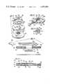
- FIG. 1is an exploded perspective view of a single terminal electrode, including the cover member;
- FIG. 2is an assembled view of the electrode of FIG. 1, with a lead wire connector attached to the electrode assemblage;
- FIG. 3is a plan view of the semi-flexible, plastic-like terminal bearing sheet, with the adhesive layer applied thereto;
- FIG. 4is an exploded sectional view of the electrode of FIG. 3;
- FIG. 5is a sectional view taken along the line 5--5 of FIG. 3;
- FIG. 6is a partial sectional view of one form of connector arrangement to be employed with the electrode asemblage of FIGS. 1 and 2 and the electrode tab segment engaged therewith;
- FIG. 7is a longitudinal sectional view of the connector of FIG. 6 with the tab portion of the electrode disengaged;
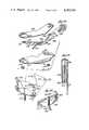
- FIG. 8is a partial sectional view of an alternate form of connector to that as shown in FIG. 6;
- FIG. 9is a longitudinal, partial sectional view of the connector form of FIG. 8, with the tab segment of the electrode disengaged;
- FIG. 10is an exploded perspective of an alternate form of electrode assemblage constructed in accordance with the invention.
- FIG. 11is an exploded sectional view of the electrode as illustrated in FIG. 10;
- FIG. 12is a sectional view of the electrode embodiment in FIG. 10 adhered to the skin of a patient;
- FIG. 13is a schematic, diagrammatic view illustrating the respective steps of a method of constructing the electrode assemblage of FIGS. 1-5;
- FIG. 14is a partial schematic view illustrating several of the steps in the method of assembly as illustrated in FIG. 13;
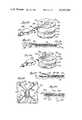
- FIG. 15is a plan view of a multi-terminal electrode, constructed in accordance with the present invention, with an upper foam layer removed from the left hand portion of the assemblage, as viewed;
- FIG. 16is a view of the adhesively coated surface of the electrode of FIG. 15, illustrating the reverse side of said electrode and the application of a deactivating compound to certain portions of said adhesively coated surface;
- FIG. 17is a partial sectional view of the connector portion of the electrode of FIG. 15, taken along the lines 17--17 of said FIG. 15;
- FIG. 18is a partial sectional view through one of the terminal portions and the gel pad of the electrode assemblage of FIG. 15 taken along the line 18--18;
- FIG. 19is a partial, exploded view of the electrode construction as illustrated in FIG. 15;
- FIG. 20is a partial plan view of an extension portion on the semi-flexible plastic sheet at which a terminal portion of the conductive ink pattern is shown;
- FIG. 21is a perspective view of the manner in which the electrode assemblage of FIG. 15 is prepared for packaging;
- FIG. 22is a perspective view illustrating the electrode assemblage in the pre-packaged construction
- FIG. 23is a sectional view taken along the line 23--23 of FIG. 22;
- FIG. 24is an exploded perspective view of still another type or form of electrode design in accordance with the invention.
- FIG. 25is a sectional view along the line 25--25 of FIG. 24;
- FIG. 26is a perspective view similar to FIG. 24, and illustrating an alternate form of connection of the electrode to a lead wire;
- FIG. 27is a sectional view taken through a completed electrode of FIG. 26, generally along the line 26--26;
- FIG. 28is a plan view of a multi-terminal electrode constructed in accordance with the design of FIG. 24, and having pre-attached lead wires;
- FIG. 29is a sectional view taken along the line 29--29 of FIG. 28, and illustrating the crimp-type connection for the lead wires.
- FIGS. 1-9The first embodiment is encompassed by FIGS. 1-9, and relates to a single terminal electrode assemblage designated generally 30 which is employed with a lead wire and connector assembly 32 and utilizes the relatively thick, foam type support arrangement or layer.
- FIGS. 10-12illustrate an alternate form of a single terminal design 80 which is adapted for use with the assembly 32 (not shown in said figures).
- This alternate design 80employs a support arrangement which is comprised of a relatively thick foam ring to provide the desired gel column, and a thinner, more extensive microporous layer, which mircoporous layer includes the adhesive material employed to affix the electrode to the skin of a patient.
- FIGS. 1-9The first embodiment is encompassed by FIGS. 1-9, and relates to a single terminal electrode assemblage designated generally 30 which is employed with a lead wire and connector assembly 32 and utilizes the relatively thick, foam type support arrangement or layer.
- FIGS. 10-12illustrate an alternate form of a single terminal design 80 which is adapted for use with the assembly 32 (not
- FIGS. 13 and 14there is shown rather schematically, a method of assemblage for the electrode construction 30 of FIGS. 1-5.
- a multi-terminal electrode construction in accordance with the present inventionis shown in FIGS. 15-23, and designated generally 120.
- Still a further type of electrode constructionis shown in FIGS. 24-29, wherein the support arrangement is provided by a conductive adhesive layer, thereby enabling elimination of the foam and/or microporous layers as well as the porous matrix.
- FIGS. 24-29wherein the support arrangement is provided by a conductive adhesive layer, thereby enabling elimination of the foam and/or microporous layers as well as the porous matrix.
- the electrode construction 30includes a base or support arrangement 36 in the form of a layer of foam-like plastic material such as polyethylene foam which material is preferably of a non-reticulated or closed cellular construction to prevent absorption of the gel material.
- the base or support layer 36includes a generally central aperture 38 extending completely through the layer 36.
- One surface of the support arrangement provided by the foam layer 36includes a coating 40 of an adhesive material (FIGS. 4 and 5), which adhesive material may be any of a number of commercially available medical grade adhesives presently in use with prior art types of electrodes, and thereby well known in the art.
- a sheet of semi-flexible plastic-like material 42which is secured in overlying relation with respect to the aperture 38 by means of an extremely thin ring-like component or layer 43 having adhesively coated surfaces 45 and 47 on opposite sides thereof; said component being termed hereinafter "a double sided adhesively coated annulus".
- the assemblage of the sheet of plastic-like material 42 to the support layer 36in effect closes one end of the aperture 38 and serves to cooperate therewith to define a well or chamber 38' for a purpose to be discussed.
- the sheet 42is referred to as constructed of a "semi-flexible, plastic-like material" for purposes of description and general definition.
- the semi-flexible, plastic-like sheet 42has terminal means thereon in the form of a conductive ink pattern 44 printed directly on one surface of said sheet. Due to the clear nature of the preferred material for the semi-flexible sheet 42, this pattern is visible from the opposite surface of said sheet.
- the pattern 44 of the disclosed embodiment 30includes a generally circular terminal portion 46 and a conductor portion 48. As can best be seen in FIG. 1, the conductor portion 48 extends from the terminal portion 46 along a tab segment 50 of said sheet 42, which tab segment includes a pair of notches 52 for the purpose to be discussed.
- a porous matrix or gel pad 54Disposed in the wall 38' is a porous matrix or gel pad 54, preferably formed of an open cellular sponge like plastic material.
- electrolytic gelno reference character
- This electrolytic gelcan be any of various commercially available products, as for example sodium chloride in agar.
- the employment of said electrolytic gelmay be dispensed with, without variation in the overall construction.
- the double sided adhesive annulus 43includes an aperture 56 which is smaller in diameter than the aperture 38 in foam layer 36, and upon assembly, surrounds the terminal portion 46 without overlying said terminal portion, FIG. 3.
- a portion 47a of the adhesive coating 47 on said ring 43is exposed interiorly of the aperture 38, as best seen in FIG. 3.
- said matrix 54is adhered to the semi-flexible plastic-like sheet 42 by means of the exposed adhesive portion 47a.
- the cover 34is applied to the adhesively coated surface 40 of the foam layer 36, said cover 34 overlying said surface 40, as well as the gelled matrix 54.
- the cover 34is preferably constructed of a high density polyethylene having a release containing on the surface thereof engaged against the adhesively coated surface 40 of the foam layer 36. As such, when it is desired to utilize the electrode, the cover 34 can be removed easily and the electrode construction applied to the skin of the patient, with the adhesive surface 40 providing the means for affixing and maintaining the electrode in proper position.
- the ink utilizedis applied by conventional printing techniques in an extremely thin layer, 0.001-0.010".
- patterns other than the pattern 44 as specifically illustratedmay be easily employed.
- Ink of the general type contemplatedis comprised of a composition of a conductive metal, carried within a binder. It is preferred that the ink utilized employ silver as the conductive component. Ink of this nature can be obtained from numerous sources, one such source being E. I. DuPont DeNemours and Company. The particular compositions available from this company include silver in a proprietary binder system specifically designed to adhere to a plastic-like material such as "MYLAR" without peeling or cracking during flexure of said material.
- the material used for the plastic-like sheet or substrate 42must be sufficiently rigid to resist any stretching or deformation during normal use or assembly. Should stretching occur, the danger exists that the ink pattern will be fractured, destroying its continuity and the ability of said conductive pattern 44 to function as an electrical terminal arrangement.
- the surface of the terminal portion 46 of said conductive silver ink patternbe chlorided to produce a thin silver chloride coating, which has proven to provide superior performance. This process of chloriding can be accomplished in any one of several known manners, such as electrodeposition or by reaction with chlorine gas.
- An additional feature of the inventionis the construction of the sheet 42 with its tab portion 50, and the location of the adhesively coated annulus 43 thereon, as best seen in FIG. 3.
- the sheet 42is fabricated and the conductive ink pattern 44 is printed thereon prior to application of the adhesive annulus 43.
- the adhesive annulus 43includes an aperture 56, such that upon its application to a surface of the semi-flexible sheet 42, it will encompass the terminal portion 46 of the conductive ink pattern 44, but preferably does not cover or overlie said terminal portion 46.
- the adhesively coated annulusextends only to the general periphery of the main segment of the sheet 42, and does not extend along the tab segment 50, thus overlying only partially the conductor portion 48.
- the annulus 43also serves to seal the gel matrix chamber 38' and prevent migration or leakage of the gel along the tab segment 50.
- the free or unsecured nature of the tab segment 50enables the electrode to be connected to ECG apparatus by means of a lead wire arrangement 32 having an electrical connector 60.
- the tab segment 50is engaged with or received within the electrical connector 60 and a connection is made with the conductor portion 48 on said tab segment 50. Details of two preferred or anticipated designs for connectors 60 are illustrated in FIGS. 6-9 and will be discussed more fully hereinafter. While these specific designs are believed to be novel per se, it is also believed that the general concept utilizing a free tab segment and a printed ink conductor segment thereon to achieve electrical connection with the lead wire arrangement 32 is a novel concept.
- the connector 60includes a housing 62 having an open end 63 leading to the interior thereof, wherein there is mounted a spring-type clip terminal 64 having upper and lower arms 65 and 66, respectively.
- a lead wire 68passes inwardly of the housing with the housing being crimped to engage said lead wire at 69, said wire 68 being connected to the terminal 64.
- the projections 70are sized and spaced apart such that upon disposition of the tab segment 50 within the housing, the projections 70 will be received within the notches 52 of said tab segment.
- the tab segment 50is received between the spring-like arms 65 and 66 with the upper spring arm 65 forcing the tab segment downwardly to maintain the tab segment engaged over the projections 70. Accordingly, if any tension is applied to the lead wire 68, the engagement of the projections 70 in the notches 52 will serve to resist inadvertent disconnection, and also function to achieve a degree of strain relief, isolating any stress from the area of the electrode terminal portion 46. It can be appreciated further, the metal terminal 64 is designed to engage the printed ink conductor portion 48 on the tab segment 50, thereby effecting an electrical connection. Further, since said metal terminal 64 includes a pair of opposed arms 65 and 66, inverting of the connector 60 upon assembly would not preclude attainment of a proper electrical connection.
- FIGS. 8 and 9illustrate a modified type of connector 60' for use with a tab segment 50 having an aperture 72 formed thereon.
- the connector housing 62'has a projection or post 74 formed thereon, and sized for disposition in said aperture 72. Accordingly, in the assembled or engaged position, as shown in FIG. 8, the spring terminal 64' will engage the printed ink conductor portion 48 to effect the desired electrical connection, and also maintain the tab segment 50 engaged over the post 74.
- FIGS. 10-12A modified form of electrode construction in accordance with the present invention is illustrated in FIGS. 10-12, and designated generally 80.
- the electrode embodiment 80differs from the electrode construction 30 in that the support arrangement includes a relatively thick ring 82 which may be made of a foam material or a rigid plastic, and a section of microporous tape material 84 having an adhesive coating 86 on one surface thereof for adhering the electrode to the skin of a patient.
- the ring 82includes a central aperture 83, while the section of microporous tape 84 has an aperture 85 of a somewhat smaller dimension, for a purpose to be discussed more fully hereinafter.
- microporous tape layerprevents dermatalogical problems as it allows air to reach the patient's skin surface.
- Suitable types of medical grade of microporous tapeare available and well known in the art, one being sold under the trade name "MICROPORE” by the 3M Company, and another by Johnson & Johnson under the trademark "DERMICIL”.
- the remaining construction of the electrode 80is somewhat similar to that of the electrode 30 discussed above, in that the terminal arrangement is provided by a semi-flexible plastic-like sheet 42 of identical construction to that previously detailed, said sheet including a tab portion 50, a pattern 44 printed thereon with the conductive ink and defining a terminal portion 46 and a conductor portion 48.
- a double-sided adhesive annulus 43is used to affix the semi-flexible sheet 42 to the upper surface of the ring 82, with the tab 50 remaining free of any connection thereto.
- the lower surface of the ring 82as mentioned previously, includes an adhesive layer 86, which affixes the ring 82 to the upper surface of the micro-porous disc 84.
- the application of the semi-flexible plastic-like sheet 42 to the ring 82serves to define a well 83' in which a porous matrix 54 is disposed.
- the double-sided adhesive annulus 43has a central aperture somewhat smaller than the aperture 83 of the ring, such that a portion of the adhesive will be exposed with the porous matrix 54 secured thereto.
- a cover member 34is provided, having an upper surface 34' upon which there is provided a release liner coating which enables the cover 34 to be removed easily immediately prior to application of the electrode to the skin of a patient.
- the assembled electrode construction 80is shown mounted to the skin 90 of a patient. It can be seen that the relatively thick ring 82 serves to provide a substantial well 83' for the gel pad 54, which also defines the height of the gel column. Further, it should be noted that the aperture 85 in the microporous support arrangement component 84 is of slightly smaller dimension than the gel matrix 54, so as to overlap slightly said matrix in the assembled condition. This overlapping design serves to further retain the gel matrix 54 in position, and prevent migration of the gel along the interface with the patient's skin 90.
- FIGS. 13 and 14wherein a preferred method of manufacture of the electrode construction 30 is shown, the illustration therein depicting the successive steps of said methods in somewhat schematic fashion.
- an elongate strip 100 of foam material 36 in roll formis provided, with said strip 100 having a first release liner 102 covering the adhesive surfaces 40 thereon.
- the strip material 100is oriented for feeding to a first station I with the release liner 102 facing upwardly.
- the apertures 38are formed in the strip 100 by a die or punch 104 at spaced successive locations along the strip.
- the double-sided adhesively coated annulus or ring 43is applied to the sheet of semi-flexible plastic-like material 42, to attain a preassembled component as was illustrated and discussed with respect to FIG. 3.
- the printed ink conductor pattern 44is applied to a section of plastic-like sheet material by a conventional printing process (not shown) and the sheet material die cut or otherwise formed to the desired shape for the sheet 42.
- the preassembled terminal bearing sheet 42 and adhesive annulus 43are affixed to the undersurface of the strip 100 at station III.
- the resulting assemblyis illustrated in the left hand portion of said FIG. 14, as viewed, which illustrates the lower surface of the strip 100 at station III.
- the semi-flexible clear sheet 42is positioned such that the terminal portion 46 of the conductive pattern 44 is aligned with the aperture 38.
- the strip 100has been rotated 180°, such that the upper surface carrying the first release liner 102 is the facing surface.
- a portion 47a of the adhesive annulus 43extends inwardly of the aperture 38 and is disposed in surrounding relationship to the terminal portion 46. This is the condition of the partially assembled electrode construction, as it is presented to station IV.
- a precut porous matrix 54is supplied and disposed within the aperture 38, this results in the matrix adhering to the adhesive portion of 47a. This step is also illustrated in the central portion of FIG. 14.
- the strip 100next passes to the station V, wherein a quantity of electrolytic gel is injected into said matrix, which gel impregnates the matrix 54 and fills the well 38'.
- a dispenser 106will meter out a pre-determined quantity of the gel to prevent over filling of the gel chamber.
- the strip 100then passes to station VI, at which the apertured, first release liner 102 is removed and discarded as waste. As can be seen, the apertured release liner 102 is coiled for easy disposition, as illustrated 108.
- the strip 100 with the partially assembled electrode thereonnext passes to the station VII, at which a second release liner 34 is applied.
- the second release liner 34is preferably a high density polyethylene sheet with a release liner coating 34' thereon, which material ultimately forms the cover for the pregelled electrode 30.
- the second release liner material 34is in roll form 110, and is applied to the strip 100 by a roller 112.
- the basic construction for the electrode 30is complete.
- a die cutter or punch 114severs the completed electrode construction 30 from the strip 100.
- the remaining portion of the strip 100thus becomes waste and can be easily discarded, as the adhesively coated surfaces thereon remains covered by the waste portion of the release liner 34.
- FIGS. 15-23there is illustrated a multi-terminal electrode, designated generally 120, and constructed in accordance with the present invention.
- Multi-terminal electrode constructions of this natureare often referred to in the art as "back pads", in that they are affixed to the patient's back to provide monitoring during chest or abdominal surgery and during recovery thereafter, wherein it would be impractical to utilize chest mounted electrodes.
- the multi-terminal electrode illustratedis of the "back pad” type, it is to be kept in mind that other types of multi-terminal electrodes such as used in muscle stimulation, electromyographic monitoring or pain therapy may also be constructed in accordance with this invention; as such with respect to multi-terminal designs, the embodiment of FIG. 15 to be discussed is merely illustrative of one preferred type, and the invention is not limited thereto.
- the multi-terminal electrode construction 120contemplates employment of a preconnected lead wire arrangement 122, including a plurality of separate lead wires 123.
- a preconnected lead wire arrangement 122including a plurality of separate lead wires 123.
- the electrode 120 as shown in FIG. 15has a sheet-like component or layer removed from the left-hand portion as viewed for purposes of illustration.
- the electrode 122is comprised of a support arrangement provided by a pair of similarly shaped sections of relatively thick foam material 124.
- foam material 124includes a pair of spaced apertures 126 formed therein.
- a singular section or sheet of semi-flexible, plastic-like material 128is provided, said sheet being mounted to each of the foam sections 124 and in effect interconnecting said sections 124 by bridging the space or joint therebetween.
- the semi-flexible sheet 128is preferably constructed of a plastic-like material of the same type as discussed with respect to electrodes 30 and 80, that is the term being "semi-flexible” being used to designate a type of material, such as "MYLAR", which will flex slightly, but will not stretch or permanently deform during normal use, assembly or storage.
- Said semi-flexible plastic-like sheet 128which will be discussed in greater detail hereinafter, is initially affixed to the foam sections 124 by a partial adhesive coating on the upper surfaces of the foam sections 124 in the areas 130, as indicated.
- a second relatively thin foam layer or sheet 132is employed which has an adhesive coating on the under surface thereof.
- said sheet 132Upon assembly of said second sheet 132, as illustrated in the right hand portion of FIG. 15, said sheet 132 overlies the semi-flexible plastic-like sheet 128 and is secured to both said sheet 128 and the upper surface of the foam layer 124 by said adhesive coating. It should be noted that while it is preferred that the layer or sheet 132 be of a foam or cellular material, other suitable materials may be employed.
- the sheet 128will be discussed primarily with the left hand portion of FIG. 15 and FIG. 19, it being understood that the right hand portion of said sheet is essentially identical, being a mirror image of that as illustrated. Further, with regard to FIG. 19, which is an exploded view of the electrode construction 120, the left hand portion of said sheet 128 can be viewed in somewhat greater detail.
- the sheet 128includes a plurality of arm sections or extensions 136 eminating from a base or central section 150, each of which terminates in generally circular portion 138. Each of the respective circular portions 138 includes an aperture 140 formed therein, as is best illustrated in FIG. 20.
- a plurality of individual terminal means corresponding in number to the apertures 126 in the sheet 124are provided on the semi-flexible sheet 128.
- the terminal means in the preferred form of the inventionare provided by four individual patterns 144, printed on the underside of the semi-flexible sheet 128 with a conductive ink of the same general type and in the same manner as discussed previously. Each pattern 144 includes a terminal portion 146 and an elongate conductor portion 148. As best shown in FIG.
- the terminal portion 146 of the illustrated embodimentis of ring-like configuration, encircling the aperture 140, with the conductor portion 148 extending along the arm or extension 136.
- the respective conductor portions 148 on each half of the sheet 136extend in opposite directions, and terminate adjacent to each other on the base or central segment 150 of said sheet.
- the lead wire arrangement 122is affixed to the base segment 150 and electrical contact with the conductor portions 148 is attained in a manner which will be discussed more fully hereinafter with respect to FIG. 17.
- Completing the basic electrode construction 120are a plurality of porous matrix members 154 which are engaged in the apertures 126, as best shown in FIG. 18.
- the circular end portion 138 on the respective extensions 136are of a diameter slightly less than that of the openings 126. Accordingly, when the semi-flexible plastic-like sheet 128 is mounted in position as shown in FIG. 15, the circular end segments 138 overlie the apertures 126 only partially.
- a suitable crimp-type terminal connector 162is included on the ends of the individual lead wires 123, the crimp-type terminal being engaged through the upper surface of the semi-flexible plastic-like sheet 120 at location 160, and bent over to effect firm electrical contact with the conductor portion 148 on the under surface of said sheet.
- the relatively thin foam like sheet 132is engaged over the terminal connections 162, and is adhered in firm engagement to the plastic-like sheet about the area of said terminal connection 162, such that the engagement of said sheet with the terminal connection and its associated lead wire 123 serve to provide a measure of strained relief. As such any tension applied to the lead wires 123 will be taken up, at least partially, by the engagement of the flexible sheet 132 with the lead wire 123.
- the under surface of the electrode 120is shown with said electrode in the fully open condition.
- the under surface of the respective support layers or sheets 124is coated with a conventional medical grade adhesive for attachment of the electrode to the skin of the patient. Since the extent of the adhesive on the under surface is rather large, and further since it is not always desirable nor necessary to have the entire surface area of the electrode in adhesive contact with a patient's skin, a portion of adhesive is deactivated to avoid dermatological problems which may occur after extended periods of use of the electrode or back pad 120.
- a medical grade silicone coatingas designated generally 164, is applied to the central area of each of support arrangement 124, as indicated. This coating in effect deactivates the adhesive in said central area, with the adhesive on the remaining portion, the areas surrounding the apertures 126 and gel pads 154, remain active and capable of effecting attachment of the electrode.
- the support arrangement for the preferred designutilizes a pair of separate, similarly shaped sheet sections 124, maintained in assembly by their joint connection to the plastic like sheet 128.
- This arrangementis for a specific purpose which will be discussed; however, it should be kept in mind that the present invention also envisions use of but a single support arrangement wherein the respective halves are provided by a single layer or sheet of foam material.
- the purpose for use of the arrangement wherein the semi-flexible plastic-like sheet 128 interconnects the respective layers 124is to attain flexibility. More specifically, it can be appreciated that these back pads are rather extensive.
- the central portion 150 of the plastic-like sheet 128provides a hinge which permits the respective halves of the electrode to flex and adjust to the contour of the patient's back. Also, as will be apparent in conjunction with the discussion to follow with regard to FIGS. 21-23, this flexibility facilitates packaging of the electrode 120.
- the semi-flexible plastic-like sheet 128provides a hinge between the respective foam sections 124 of the support arrangement.
- This hinge area, the central segment 150 of the sheet 128,does not include portions of the conductive pattern 144 providing the terminal means. Accordingly, the respective foam layers 124 may be folded over upon themselves, as is indicated in FIG. 21, without undue flexing of the pattern 144.
- a sheet of release liner material 168is disposed intermediate the respective halves of the electrode, said sheet 168 having a release coating on both sides thereof.
- the respective halves or sections 124 of the electrodeare releasably secured against said sheet 168 in overlapped relation, as is best illustrated in FIGS. 22 and 23, with the lead wire arrangement 122 coiled as illustrated.
- the lead wire arrangement 122coiled as illustrated.
- FIGS. 24-29a still further modified version of the present invention is illustrated.
- FIGS. 24-27there is shown two forms of a single terminal electrode construction, designated 170 and 170' respectively.
- FIGS. 28 and 29there is shown a multi-terminal electrode construction using the general concept as to be discussed with respect to the single terminal electrodes 170 and 170'.
- the electrode 170differs from the electrode 30, previously discussed, primarily in that the foam layer 36 and the gelled matrix 54 have been replaced by a specially constructed conductive adhesive layer 171. More specifically, the electrode 170 of FIG. 24 is illustrated in exploded fashion with the assembled arrangement being shown in FIG. 25, affixed to a patient.
- the electrode 170is comprised of a sheet of semi-flexible plastic-like material 172 upon which is printed a conductive pattern 174.
- the pattern 174preferably is formed with a silver ink, or some other type of conductive ink printed directly on the sheet material as discussed previously, and said pattern 144 includes a terminal portion 176, and a conductor portion 178.
- the semi-flexible plastic-like sheet 172also includes the tab segment 180 adapted to be received within a connector 182 affixed to the end of a lead wire 184 in a manner similar to that as discussed with respect to the electrode of FIGS. 1-5. It should be noted that the conductor portion 178 extends along the length of the tab 180, which in turn extends from the periphery of the main segment of the electrode, which conductor portion 178 will be associated in electrical contact with a metal terminal housed within the connector 182.
- the layer of conductive adhesiveis affixed to the major or main segment 173 of the semi-flexible plastic-like sheet 172, but does not extend along the tab 180, whereby said tab remains free for engagement within a connector 182.
- a cover member 190, having a release liner coated surface 191is provided, which is releasably attached to the under surface of the adhesive layer 171, and can be peeled off or removed for mounting of the electrode to the skin 90 of a patient, as is shown in FIG. 25.
- the gel pad or matrix and foam support layer used with the electrodes discussed previouslyare not required. As such, the conductive adhesive layer 171 is not apertured, as was the adhesive annulus 43 discussed previously, and overlies the terminal portion 176.
- the adhesive layer 171may be provided by any one of several known electrically conductive adhesives.
- One such conductive adhesiveis produced by Johnson & Johnson Company under the trade name "BIO-HESIVE", and is disclosed in U.S. Pat. No. 4,066,078, which in turn references a pending U.S. application Ser. No. 509,207, filed Sept. 25, 1974 and entitled "Hydrophilic Random Interpolymer Compositions and Method for Making Same".
- Other conductive adhesives and methods for rendering adhesive materials conductiveare known in the art; as for example in U.S. Pat. Nos. 4,008,721; 3,998,215; 3,993,049; and 3,911,906.
- the adhesive layer 171 of the present inventionis preferably constructed of a hydrophilic adhesive composition manufactured by Tyndale-Plain-Hunter, Ltd., which material may be rendered conductive by any one of the above noted methods, or other methods known in the art.
- This hydrophilic materialis disclosed fully in U.S. Pat. Nos. 3,822,238; 4,156,066; and 4,156,067.
- the adhesive layer 171is of a double sided nature so that it has one surface secured to the semi-flexible plastic-like sheet 172 and an opposed surface for attachment to the skin of a patient.
- FIGS. 26 and 27A second or modified version of the electrode 170 is illustrated in FIGS. 26 and 27, said modified design being designated 170'.
- the electrode 170'includes a semi-flexible plastic-like sheet 172' with terminal means formed thereon preferably in the form of a printed ink conductive pattern 174' having a terminal portion 176' and a conductor portion 178'.
- the embodiment of FIGS. 26 and 27utilizes a tab 180' in the form of a cut-out depending from the main segment 173' of said sheet. The tab segment extends upwardly from said main segment 173' of the sheet 172' for attachment to a connector 182', as shown.
- the electrode 170'also utilizes the conductive adhesive layer 171', as discussed previously.
- the tab 180is coated with a medical grade of silicone or the like, during manufacture. Accordingly, upon application of the conductive adhesive layer 171', said tab 180' remains free of adhesion thereto, and can be lifted up out of the plane of the main segment 173' of a flexible sheet 172' for attachment to the conductor. Therefore, except for the manner of forming the tab 180', the electrode 170' is essentially identical to that as discussed with regard to FIGS. 24 and 25.
- the electrode 190is of the type having a lead wire assembly 193 pre-attached thereto.
- the electrode 190includes a single sheet of semi-flexible plastic-like sheet material 194 having separate individual conductive patterns, 195 printed thereon.
- Each pattern 195includes a terminal portion 196, and a conductor portion 198.
- the conductor portions 198 on each half of the semi-flexible plastic-like sheetextend in opposite directions toward each other, and terminate proximate a central segment of the sheet.
- a crimp-type terminal 197 connector carried on the end of the each lead wire of the assembly 193is engaged through the upper surface of the semi-flexible plastic-like sheet 194 and disposed in electrical contact with the conductor portion 198, of the conductive pattern 195 on the under surfaces of said semi-flexible plastic-like sheet 194.
- FIG. 29is a sectional view showing the electrode 192 engaged to the skin 90 of a patient.
- the electrode 192includes a layer of conductive adhesive 199; FIG. 29 on the under surface of sheet 194.
- a junction of dissimilar metalssuch as the copper which may be used for the terminal connection 197 and the silver or silver chloride coating on the conductor portion 198 in association with the conductive adhesive 199, as there exists the danger of electrolytic corrosion. Therefore, the joint or connection of the terminal 197 with the conductor portion 198 is hermatically sealed by placement of a quantity of epoxy or wax, or some other substance, designated generally 200, over the point of connection on the under side of the sheet 194.
- the conductive adhesive layer 199is then applied in overlying relation to the undersurface of the electrode, preferably over the entire electrode. If desired, said adhesive may be subject to zoned application, in whatever pattern desired, provided the terminal portions 196 of the conductive pattern 195 is covered.
Landscapes
- Health & Medical Sciences (AREA)
- Life Sciences & Earth Sciences (AREA)
- Biomedical Technology (AREA)
- Heart & Thoracic Surgery (AREA)
- Dispersion Chemistry (AREA)
- Biophysics (AREA)
- Pathology (AREA)
- Engineering & Computer Science (AREA)
- Chemical & Material Sciences (AREA)
- Physics & Mathematics (AREA)
- Medical Informatics (AREA)
- Molecular Biology (AREA)
- Surgery (AREA)
- Animal Behavior & Ethology (AREA)
- General Health & Medical Sciences (AREA)
- Public Health (AREA)
- Veterinary Medicine (AREA)
- Electrotherapy Devices (AREA)
Abstract
Description
Claims (6)
Priority Applications (1)
| Application Number | Priority Date | Filing Date | Title |
|---|---|---|---|
| US06/310,119US4393584A (en) | 1979-12-06 | 1981-10-09 | Method of manufacture of electrode construction |
Applications Claiming Priority (2)
| Application Number | Priority Date | Filing Date | Title |
|---|---|---|---|
| US06/100,904US4365634A (en) | 1979-12-06 | 1979-12-06 | Medical electrode construction |
| US06/310,119US4393584A (en) | 1979-12-06 | 1981-10-09 | Method of manufacture of electrode construction |
Related Parent Applications (1)
| Application Number | Title | Priority Date | Filing Date |
|---|---|---|---|
| US06/100,904DivisionUS4365634A (en) | 1979-12-06 | 1979-12-06 | Medical electrode construction |
Publications (1)
| Publication Number | Publication Date |
|---|---|
| US4393584Atrue US4393584A (en) | 1983-07-19 |
Family
ID=26797675
Family Applications (1)
| Application Number | Title | Priority Date | Filing Date |
|---|---|---|---|
| US06/310,119Expired - LifetimeUS4393584A (en) | 1979-12-06 | 1981-10-09 | Method of manufacture of electrode construction |
Country Status (1)
| Country | Link |
|---|---|
| US (1) | US4393584A (en) |
Cited By (63)
| Publication number | Priority date | Publication date | Assignee | Title |
|---|---|---|---|---|
| GB2159717A (en)* | 1984-06-08 | 1985-12-11 | Mossledge Limited | Medical electrode |
| US4559950A (en)* | 1983-11-25 | 1985-12-24 | Graphic Controls Corporation | Disposable biomedical and diagnostic electrode |
| US4606118A (en)* | 1985-02-27 | 1986-08-19 | Medtronic, Inc. | Method of making a drug dispensing body |
| EP0182576A3 (en)* | 1984-11-19 | 1987-01-21 | Harold L. Pike | Multipolar medical electrode |
| US4640289A (en)* | 1983-11-14 | 1987-02-03 | Minnesota Mining And Manufacturing Company | Biomedical electrode |
| US4700997A (en)* | 1986-11-14 | 1987-10-20 | Minnesota Mining And Manufacturing Company | Electrical connector |
| US4727881A (en)* | 1983-11-14 | 1988-03-01 | Minnesota Mining And Manufacturing Company | Biomedical electrode |
| EP0275628A1 (en)* | 1986-12-24 | 1988-07-27 | Nitto Denko Corporation | Conductive electrode having a connection portion |
| EP0284943A1 (en)* | 1987-03-30 | 1988-10-05 | Fukuda Denshi Co., Ltd. | Multi-electrode type electrocardiographic electrode structure |
| US4795516A (en)* | 1986-05-21 | 1989-01-03 | Minnesota Mining And Manufacturing Company | Method of continuous production of a biomedical electrode |
| US4798642A (en)* | 1983-11-14 | 1989-01-17 | Minnesota Mining And Manufacturing Company | Method of making a biomedical electrode |
| EP0194823A3 (en)* | 1985-03-12 | 1989-03-01 | BAXTER INTERNATIONAL INC. (a Delaware corporation) | Medical electrode |
| US4822445A (en)* | 1986-11-21 | 1989-04-18 | Fuji Photo Film Co., Ltd. | Apparatus for processing double face adhesive tape |
| US4842558A (en)* | 1988-10-14 | 1989-06-27 | Minnesota Mining And Manufacturing Company | Electrical connector |
| EP0180735B1 (en)* | 1984-11-06 | 1990-12-12 | Drägerwerk Aktiengesellschaft | Electrode array adapted to a measuring transducer |
| US4989607A (en)* | 1989-03-30 | 1991-02-05 | Preston Keusch | Highly conductive non-stringy adhesive hydrophilic gels and medical electrode assemblies manufactured therefrom |
| WO1991005509A1 (en)* | 1989-10-11 | 1991-05-02 | Eric Thomas Mcadams | Biosignal electrode |
| GB2251798A (en)* | 1989-10-11 | 1992-07-22 | Eric Thomas Mcadams | Biosignal electrode |
| US5143071A (en)* | 1989-03-30 | 1992-09-01 | Nepera, Inc. | Non-stringy adhesive hydrophilic gels |
| US5191886A (en)* | 1991-04-18 | 1993-03-09 | Physio-Control Corporation | Multiple electrode strip |
| US5311658A (en)* | 1992-04-06 | 1994-05-17 | Fukuda Denshi Co., Ltd. | Apparatus for producing living body leading electrode |
| US5341806A (en)* | 1991-04-18 | 1994-08-30 | Physio-Control Corporation | Multiple electrode strip |
| US5540033A (en)* | 1994-01-10 | 1996-07-30 | Cambrex Hydrogels | Integrated Manufacturing process for hydrogels |
| US5566672A (en)* | 1994-01-03 | 1996-10-22 | Labeltape Meditect, Inc. | Biomedical electrode |
| EP0782837A1 (en)* | 1990-06-21 | 1997-07-09 | Cardiotronics International, Inc. | Electrodeless EKG sensor sheet |
| WO1997024156A1 (en)* | 1995-12-29 | 1997-07-10 | Minnesota Mining And Manufacturing Company | Self-packaging bioelectrodes |
| US5713128A (en)* | 1996-02-16 | 1998-02-03 | Valleylab Inc | Electrosurgical pad apparatus and method of manufacture |
| EP0737438A3 (en)* | 1995-04-12 | 1999-03-10 | R.S. Supplies, Inc. | Medical electrode |
| US6546617B1 (en)* | 1999-04-02 | 2003-04-15 | Denso Corporation | Method of peeling off coating of insulated conductive wires |
| US20060224150A1 (en)* | 2005-03-31 | 2006-10-05 | Sherwood Services Ag | Temperature regulating patient return electrode and return electrode monitoring system |
| US7119689B2 (en) | 2003-09-19 | 2006-10-10 | Vesta Medical, Llc | System and method for sorting medical waste for disposal |
| US20070073284A1 (en)* | 2002-09-25 | 2007-03-29 | Sturm Thomas A | Multiple RF return pad contact detection system |
| US20070113964A1 (en)* | 2001-12-10 | 2007-05-24 | Crawford Scott A | Small water-repellant microphone having improved acoustic performance and method of constructing same |
| US20070167942A1 (en)* | 2006-01-18 | 2007-07-19 | Sherwood Services Ag | RF return pad current distribution system |
| US7275645B2 (en) | 2003-09-19 | 2007-10-02 | Vesta Medical, Llc | Handheld medical waste sorting device |
| US7303081B2 (en) | 2003-09-19 | 2007-12-04 | Vesta Medical, Llc | Handheld medical waste sorting method |
| US7311207B2 (en) | 2003-09-19 | 2007-12-25 | Vesta Medical, Llc | System for sorting discarded and spent pharmaceutical items |
| US7318529B2 (en) | 2003-09-19 | 2008-01-15 | Vest Medical, Llc | Method for sorting discarded and spent pharmaceutical items |
| US20080083813A1 (en)* | 2006-10-05 | 2008-04-10 | Michael Zemlok | Method and force-limiting handle mechanism for a surgical instrument |
| US20090036885A1 (en)* | 2007-08-01 | 2009-02-05 | Gregg William N | System and method for return electrode monitoring |
| US7562025B2 (en) | 2003-09-19 | 2009-07-14 | Vesta Medical, Llc | Waste sorting system with query function, and method thereof |
| US7637907B2 (en) | 2006-09-19 | 2009-12-29 | Covidien Ag | System and method for return electrode monitoring |
| US7660724B2 (en) | 2003-09-19 | 2010-02-09 | Vesta Medical, Llc | Waste sorting system utilizing removable liners |
| US7722412B2 (en) | 2001-06-01 | 2010-05-25 | Covidien Ag | Return pad cable connector |
| US7736359B2 (en) | 2006-01-12 | 2010-06-15 | Covidien Ag | RF return pad current detection system |
| EP2229881A1 (en)* | 2009-03-19 | 2010-09-22 | Covidien AG | Biomedical electrode |
| US7927329B2 (en) | 2006-09-28 | 2011-04-19 | Covidien Ag | Temperature sensing return electrode pad |
| US7970722B1 (en) | 1999-11-08 | 2011-06-28 | Aloft Media, Llc | System, method and computer program product for a collaborative decision platform |
| US8021360B2 (en) | 2007-04-03 | 2011-09-20 | Tyco Healthcare Group Lp | System and method for providing even heat distribution and cooling return pads |
| US8062291B2 (en) | 2006-09-28 | 2011-11-22 | Covidien Ag | Smart return electrode pad |
| US8080007B2 (en) | 2007-05-07 | 2011-12-20 | Tyco Healthcare Group Lp | Capacitive electrosurgical return pad with contact quality monitoring |
| US8195328B2 (en) | 2003-09-19 | 2012-06-05 | Vesta Medical, Llc | Combination disposal and dispensing apparatus and method |
| US8231614B2 (en) | 2007-05-11 | 2012-07-31 | Tyco Healthcare Group Lp | Temperature monitoring return electrode |
| US8323675B2 (en) | 2004-04-20 | 2012-12-04 | Genzyme Corporation | Soft tissue prosthesis for repairing a defect of an abdominal wall or a pelvic cavity wall |
| US8388612B2 (en) | 2007-05-11 | 2013-03-05 | Covidien Lp | Temperature monitoring return electrode |
| US20130180523A1 (en)* | 2010-09-03 | 2013-07-18 | Qinetiq Limited | Respiratory protection equipment |
| US8641210B2 (en) | 2011-11-30 | 2014-02-04 | Izi Medical Products | Retro-reflective marker including colored mounting portion |
| US8661573B2 (en) | 2012-02-29 | 2014-03-04 | Izi Medical Products | Protective cover for medical device having adhesive mechanism |
| US8662347B2 (en) | 2010-09-29 | 2014-03-04 | Covidien Lp | Medical electrode dispensers |
| US8801703B2 (en) | 2007-08-01 | 2014-08-12 | Covidien Lp | System and method for return electrode monitoring |
| US8962062B2 (en) | 2012-01-10 | 2015-02-24 | Covidien Lp | Methods of manufacturing end effectors for energy-based surgical instruments |
| WO2021208823A1 (en)* | 2020-04-13 | 2021-10-21 | 山东华滋自动化技术股份有限公司 | Fastening coating device |
| WO2022229099A1 (en)* | 2021-04-27 | 2022-11-03 | Ambu A/S | Medical electrode |
Citations (24)
| Publication number | Priority date | Publication date | Assignee | Title |
|---|---|---|---|---|
| US3380445A (en)* | 1965-09-24 | 1968-04-30 | Int Rectifier Corp | Electrical pickup structure for electrocardiographs and the like |
| US3599629A (en)* | 1968-08-28 | 1971-08-17 | Lexington Instr | Oxidized surface biopotential skin electrode |
| US3720209A (en)* | 1968-03-11 | 1973-03-13 | Medical Plastics Inc | Plate electrode |
| US3805769A (en)* | 1971-08-27 | 1974-04-23 | R Sessions | Disposable electrode |
| US3828766A (en)* | 1972-08-14 | 1974-08-13 | Jet Medical Prod Inc | Disposable medical electrode |
| US3911906A (en)* | 1974-04-24 | 1975-10-14 | Survival Technology | Dry applied and operably dry electrode device |
| GB1441622A (en) | 1972-07-24 | 1976-07-07 | Medical Plastics Ind | Bioelectric pickup electrodes |
| US3972329A (en)* | 1974-11-25 | 1976-08-03 | Kaufman John George | Body electrode for electro-medical use |
| US3989035A (en)* | 1975-08-04 | 1976-11-02 | Stemmen Laboratory, Inc. | Disposable medical electrode |
| US3993049A (en)* | 1974-12-26 | 1976-11-23 | Kater John A R | Electrodes and materials therefor |
| US3998215A (en)* | 1968-12-18 | 1976-12-21 | Minnesota Mining And Manufacturing Company | Bio-medical electrode conductive gel pads |
| US4008721A (en)* | 1975-04-14 | 1977-02-22 | Medtronic, Inc. | Tape electrode for transmitting electrical signals through the skin |
| US4034854A (en)* | 1976-07-16 | 1977-07-12 | M I Systems, Inc. | Electrode package |
| US4050453A (en)* | 1976-02-03 | 1977-09-27 | Concept, Inc. | Radiotransparent electrode |
| US4051842A (en)* | 1975-09-15 | 1977-10-04 | International Medical Corporation | Electrode and interfacing pad for electrical physiological systems |
| US4066078A (en)* | 1976-02-05 | 1978-01-03 | Johnson & Johnson | Disposable electrode |
| US4082087A (en)* | 1977-02-07 | 1978-04-04 | Isis Medical Instruments | Body contact electrode structure for deriving electrical signals due to physiological activity |
| US4114263A (en)* | 1977-03-14 | 1978-09-19 | Roman Szpur | Method of manufacturing medical electrodes |
| US4117846A (en)* | 1976-05-07 | 1978-10-03 | Consolidated Medical Equipment | Skin conducting electrode and electrode assembly |
| US4125110A (en)* | 1975-11-25 | 1978-11-14 | Hymes Alan C | Monitoring and stimulation electrode |
| US4126126A (en)* | 1976-07-27 | 1978-11-21 | C. R. Bard, Inc. | Non-metallic pregelled electrode |
| US4141366A (en)* | 1977-11-18 | 1979-02-27 | Medtronic, Inc. | Lead connector for tape electrode |
| US4166465A (en)* | 1977-10-17 | 1979-09-04 | Neomed Incorporated | Electrosurgical dispersive electrode |
| US4257424A (en)* | 1979-04-30 | 1981-03-24 | Ndm Corporation | X-ray transparent medical electrode |
- 1981
- 1981-10-09USUS06/310,119patent/US4393584A/ennot_activeExpired - Lifetime
Patent Citations (25)
| Publication number | Priority date | Publication date | Assignee | Title |
|---|---|---|---|---|
| US3380445A (en)* | 1965-09-24 | 1968-04-30 | Int Rectifier Corp | Electrical pickup structure for electrocardiographs and the like |
| US3720209A (en)* | 1968-03-11 | 1973-03-13 | Medical Plastics Inc | Plate electrode |
| US3599629A (en)* | 1968-08-28 | 1971-08-17 | Lexington Instr | Oxidized surface biopotential skin electrode |
| US3998215A (en)* | 1968-12-18 | 1976-12-21 | Minnesota Mining And Manufacturing Company | Bio-medical electrode conductive gel pads |
| US3805769A (en)* | 1971-08-27 | 1974-04-23 | R Sessions | Disposable electrode |
| GB1441622A (en) | 1972-07-24 | 1976-07-07 | Medical Plastics Ind | Bioelectric pickup electrodes |
| US3828766A (en)* | 1972-08-14 | 1974-08-13 | Jet Medical Prod Inc | Disposable medical electrode |
| US3911906A (en)* | 1974-04-24 | 1975-10-14 | Survival Technology | Dry applied and operably dry electrode device |
| US3972329A (en)* | 1974-11-25 | 1976-08-03 | Kaufman John George | Body electrode for electro-medical use |
| US3993049A (en)* | 1974-12-26 | 1976-11-23 | Kater John A R | Electrodes and materials therefor |
| US4008721A (en)* | 1975-04-14 | 1977-02-22 | Medtronic, Inc. | Tape electrode for transmitting electrical signals through the skin |
| US3989035A (en)* | 1975-08-04 | 1976-11-02 | Stemmen Laboratory, Inc. | Disposable medical electrode |
| US4051842A (en)* | 1975-09-15 | 1977-10-04 | International Medical Corporation | Electrode and interfacing pad for electrical physiological systems |
| US4125110A (en)* | 1975-11-25 | 1978-11-14 | Hymes Alan C | Monitoring and stimulation electrode |
| US4050453A (en)* | 1976-02-03 | 1977-09-27 | Concept, Inc. | Radiotransparent electrode |
| US4066078A (en)* | 1976-02-05 | 1978-01-03 | Johnson & Johnson | Disposable electrode |
| US4117846A (en)* | 1976-05-07 | 1978-10-03 | Consolidated Medical Equipment | Skin conducting electrode and electrode assembly |
| US4034854A (en)* | 1976-07-16 | 1977-07-12 | M I Systems, Inc. | Electrode package |
| US4126126A (en)* | 1976-07-27 | 1978-11-21 | C. R. Bard, Inc. | Non-metallic pregelled electrode |
| US4082087A (en)* | 1977-02-07 | 1978-04-04 | Isis Medical Instruments | Body contact electrode structure for deriving electrical signals due to physiological activity |
| US4114263A (en)* | 1977-03-14 | 1978-09-19 | Roman Szpur | Method of manufacturing medical electrodes |
| US4166465A (en)* | 1977-10-17 | 1979-09-04 | Neomed Incorporated | Electrosurgical dispersive electrode |
| US4166465B1 (en)* | 1977-10-17 | 1985-07-09 | ||
| US4141366A (en)* | 1977-11-18 | 1979-02-27 | Medtronic, Inc. | Lead connector for tape electrode |
| US4257424A (en)* | 1979-04-30 | 1981-03-24 | Ndm Corporation | X-ray transparent medical electrode |
Cited By (125)
| Publication number | Priority date | Publication date | Assignee | Title |
|---|---|---|---|---|
| US4798642A (en)* | 1983-11-14 | 1989-01-17 | Minnesota Mining And Manufacturing Company | Method of making a biomedical electrode |
| US4727881A (en)* | 1983-11-14 | 1988-03-01 | Minnesota Mining And Manufacturing Company | Biomedical electrode |
| US4640289A (en)* | 1983-11-14 | 1987-02-03 | Minnesota Mining And Manufacturing Company | Biomedical electrode |
| US4559950A (en)* | 1983-11-25 | 1985-12-24 | Graphic Controls Corporation | Disposable biomedical and diagnostic electrode |
| WO1986000008A1 (en)* | 1984-06-08 | 1986-01-03 | Sciotronic Limited | Medical electrode |
| GB2159717A (en)* | 1984-06-08 | 1985-12-11 | Mossledge Limited | Medical electrode |
| US4721111A (en)* | 1984-06-08 | 1988-01-26 | Sciotronic Limited | Medical electrode and method of making the electrode |
| EP0180735B1 (en)* | 1984-11-06 | 1990-12-12 | Drägerwerk Aktiengesellschaft | Electrode array adapted to a measuring transducer |
| EP0182576A3 (en)* | 1984-11-19 | 1987-01-21 | Harold L. Pike | Multipolar medical electrode |
| US4606118A (en)* | 1985-02-27 | 1986-08-19 | Medtronic, Inc. | Method of making a drug dispensing body |
| EP0194823A3 (en)* | 1985-03-12 | 1989-03-01 | BAXTER INTERNATIONAL INC. (a Delaware corporation) | Medical electrode |
| US4795516A (en)* | 1986-05-21 | 1989-01-03 | Minnesota Mining And Manufacturing Company | Method of continuous production of a biomedical electrode |
| US4700997A (en)* | 1986-11-14 | 1987-10-20 | Minnesota Mining And Manufacturing Company | Electrical connector |
| US4822445A (en)* | 1986-11-21 | 1989-04-18 | Fuji Photo Film Co., Ltd. | Apparatus for processing double face adhesive tape |
| EP0275628A1 (en)* | 1986-12-24 | 1988-07-27 | Nitto Denko Corporation | Conductive electrode having a connection portion |
| US4922911A (en)* | 1986-12-24 | 1990-05-08 | Nitto Denko Corporation | Electrode |
| EP0284943A1 (en)* | 1987-03-30 | 1988-10-05 | Fukuda Denshi Co., Ltd. | Multi-electrode type electrocardiographic electrode structure |
| DE3920677A1 (en)* | 1988-10-14 | 1990-04-19 | Minnesota Mining & Mfg | ELECTRIC CONNECTOR |
| US4842558A (en)* | 1988-10-14 | 1989-06-27 | Minnesota Mining And Manufacturing Company | Electrical connector |
| DE3920677C2 (en)* | 1988-10-14 | 1999-03-11 | Minnesota Mining & Mfg | Electrical connector |
| US5143071A (en)* | 1989-03-30 | 1992-09-01 | Nepera, Inc. | Non-stringy adhesive hydrophilic gels |
| US5354790A (en)* | 1989-03-30 | 1994-10-11 | Nepera, Inc. | Methods for the preparation of non-stringy adhesive hydrophilic gels |
| US4989607A (en)* | 1989-03-30 | 1991-02-05 | Preston Keusch | Highly conductive non-stringy adhesive hydrophilic gels and medical electrode assemblies manufactured therefrom |
| US5337748A (en)* | 1989-10-11 | 1994-08-16 | Mcadams Eric T | Biosignal electrode |
| GB2251798B (en)* | 1989-10-11 | 1993-10-06 | Eric Thomas Mcadams | Biosignal electrode |
| DE4091800T1 (en)* | 1989-10-11 | 1993-11-18 | Eric Thomas Mcadams | Biosignal electrode |
| GB2251798A (en)* | 1989-10-11 | 1992-07-22 | Eric Thomas Mcadams | Biosignal electrode |
| DE4091800C2 (en)* | 1989-10-11 | 2000-09-14 | Eric Thomas Mcadams | Biosignal electrode |
| WO1991005509A1 (en)* | 1989-10-11 | 1991-05-02 | Eric Thomas Mcadams | Biosignal electrode |
| EP0782837A1 (en)* | 1990-06-21 | 1997-07-09 | Cardiotronics International, Inc. | Electrodeless EKG sensor sheet |
| US5341806A (en)* | 1991-04-18 | 1994-08-30 | Physio-Control Corporation | Multiple electrode strip |
| US5191886A (en)* | 1991-04-18 | 1993-03-09 | Physio-Control Corporation | Multiple electrode strip |
| US5311658A (en)* | 1992-04-06 | 1994-05-17 | Fukuda Denshi Co., Ltd. | Apparatus for producing living body leading electrode |
| US5566672A (en)* | 1994-01-03 | 1996-10-22 | Labeltape Meditect, Inc. | Biomedical electrode |
| US5540033A (en)* | 1994-01-10 | 1996-07-30 | Cambrex Hydrogels | Integrated Manufacturing process for hydrogels |
| EP0737438A3 (en)* | 1995-04-12 | 1999-03-10 | R.S. Supplies, Inc. | Medical electrode |
| WO1997024156A1 (en)* | 1995-12-29 | 1997-07-10 | Minnesota Mining And Manufacturing Company | Self-packaging bioelectrodes |
| US5827184A (en)* | 1995-12-29 | 1998-10-27 | Minnesota Mining And Manufacturing Company | Self-packaging bioelectrodes |
| US5713128A (en)* | 1996-02-16 | 1998-02-03 | Valleylab Inc | Electrosurgical pad apparatus and method of manufacture |
| US6546617B1 (en)* | 1999-04-02 | 2003-04-15 | Denso Corporation | Method of peeling off coating of insulated conductive wires |
| US8160988B1 (en) | 1999-11-08 | 2012-04-17 | Aloft Media, Llc | System, method and computer program product for a collaborative decision platform |
| US8005777B1 (en) | 1999-11-08 | 2011-08-23 | Aloft Media, Llc | System, method and computer program product for a collaborative decision platform |
| US7970722B1 (en) | 1999-11-08 | 2011-06-28 | Aloft Media, Llc | System, method and computer program product for a collaborative decision platform |
| US7722412B2 (en) | 2001-06-01 | 2010-05-25 | Covidien Ag | Return pad cable connector |
| US20070113964A1 (en)* | 2001-12-10 | 2007-05-24 | Crawford Scott A | Small water-repellant microphone having improved acoustic performance and method of constructing same |
| US7938825B2 (en) | 2002-09-25 | 2011-05-10 | Covidien Ag | Multiple RF return pad contact detection system |
| US20070073284A1 (en)* | 2002-09-25 | 2007-03-29 | Sturm Thomas A | Multiple RF return pad contact detection system |
| US7533028B2 (en) | 2003-09-19 | 2009-05-12 | Vesta Medical, Llc | Waste sorting method for rendering drugs non-recoverable |
| US7617113B2 (en) | 2003-09-19 | 2009-11-10 | Vesta Medical, Llc | Medical waste sorting method |
| US7296688B2 (en) | 2003-09-19 | 2007-11-20 | Vesta Medical, Llc | Apparatus for facilitating medical waste disposal |
| US7303080B2 (en) | 2003-09-19 | 2007-12-04 | Vesta Medical, Llc | Waste sensor for a disposable container |
| US7303082B2 (en) | 2003-09-19 | 2007-12-04 | Vesta Medical, Llc | Medical waste sorting system with container identification |
| US7303081B2 (en) | 2003-09-19 | 2007-12-04 | Vesta Medical, Llc | Handheld medical waste sorting method |
| US7311207B2 (en) | 2003-09-19 | 2007-12-25 | Vesta Medical, Llc | System for sorting discarded and spent pharmaceutical items |
| US7318529B2 (en) | 2003-09-19 | 2008-01-15 | Vest Medical, Llc | Method for sorting discarded and spent pharmaceutical items |
| US7341147B2 (en) | 2003-09-19 | 2008-03-11 | Vesta Medical, Llc | Disposable container for use in a waste sorting system |
| US8868434B2 (en) | 2003-09-19 | 2014-10-21 | Carefusion 303, Inc. | Waste sorting and disposal method using labels |
| US7383195B2 (en) | 2003-09-19 | 2008-06-03 | Vesta Medical, Llc | Methods of sorting waste |
| US7454358B2 (en) | 2003-09-19 | 2008-11-18 | Vesta Medical, Llc | Waste scanning method |
| US7483837B2 (en) | 2003-09-19 | 2009-01-27 | Vesta Medical, Llc | Waste sensing system |
| US7487100B2 (en) | 2003-09-19 | 2009-02-03 | Vesta Medical, Llc | Method of sorting regulated drug waste |
| US8204620B2 (en) | 2003-09-19 | 2012-06-19 | Vesta Medical, Llc | Method for combined disposal and dispensing of medical items |
| US7533029B2 (en) | 2003-09-19 | 2009-05-12 | Vesta Medical, Llc | Waste sorting system for rendering drugs non-recoverable |
| US8195328B2 (en) | 2003-09-19 | 2012-06-05 | Vesta Medical, Llc | Combination disposal and dispensing apparatus and method |
| US7562025B2 (en) | 2003-09-19 | 2009-07-14 | Vesta Medical, Llc | Waste sorting system with query function, and method thereof |
| US7565299B2 (en) | 2003-09-19 | 2009-07-21 | Vesta Medical, Llc | Waste sorting and tracking system and method |
| US7275645B2 (en) | 2003-09-19 | 2007-10-02 | Vesta Medical, Llc | Handheld medical waste sorting device |
| US7620559B2 (en) | 2003-09-19 | 2009-11-17 | Vesta Medical, Llc | System for facilitating medical waste disposal |
| US8296243B2 (en) | 2003-09-19 | 2012-10-23 | Vesta Medical, Llc | Systems for identifying and categorizing medical waste |
| US7660724B2 (en) | 2003-09-19 | 2010-02-09 | Vesta Medical, Llc | Waste sorting system utilizing removable liners |
| US7664656B2 (en) | 2003-09-19 | 2010-02-16 | Mallett Scott R | Method of sorting waste utilizing removable liners |
| US7138918B2 (en) | 2003-09-19 | 2006-11-21 | Vesta Medical, Llc | System for sorting waste |
| US8355994B2 (en) | 2003-09-19 | 2013-01-15 | Vesta Medical Llc | Sorting system for composite drugs |
| US20100219237A1 (en)* | 2003-09-19 | 2010-09-02 | Vesta Medical, Llc | Electronic systems for identifying and categorizing waste |
| US8595021B2 (en) | 2003-09-19 | 2013-11-26 | Carefusion 303, Inc. | Methods for identifying and categorizing medical waste |
| US8560460B2 (en) | 2003-09-19 | 2013-10-15 | Carefusion 303, Inc. | Automated waste sorting system |
| US7126480B2 (en) | 2003-09-19 | 2006-10-24 | Vesta Medical, Llc | Waste sorting network |
| US7123150B2 (en) | 2003-09-19 | 2006-10-17 | Vesta Medical, Llc | Waste container identification system |
| US7119689B2 (en) | 2003-09-19 | 2006-10-10 | Vesta Medical, Llc | System and method for sorting medical waste for disposal |
| US8460695B2 (en) | 2004-04-20 | 2013-06-11 | Genzyme Corporation | Making a soft tissue prosthesis for repairing a defect of an abdominal wall or a pelvic cavity wall |
| US8323675B2 (en) | 2004-04-20 | 2012-12-04 | Genzyme Corporation | Soft tissue prosthesis for repairing a defect of an abdominal wall or a pelvic cavity wall |
| US20060224150A1 (en)* | 2005-03-31 | 2006-10-05 | Sherwood Services Ag | Temperature regulating patient return electrode and return electrode monitoring system |
| US8821487B2 (en) | 2005-03-31 | 2014-09-02 | Covidien Ag | Temperature regulating patient return electrode and return electrode monitoring system |
| US7736359B2 (en) | 2006-01-12 | 2010-06-15 | Covidien Ag | RF return pad current detection system |
| US20070167942A1 (en)* | 2006-01-18 | 2007-07-19 | Sherwood Services Ag | RF return pad current distribution system |
| US7637907B2 (en) | 2006-09-19 | 2009-12-29 | Covidien Ag | System and method for return electrode monitoring |
| US8216222B2 (en) | 2006-09-28 | 2012-07-10 | Covidien Ag | Temperature sensing return electrode pad |
| US8062291B2 (en) | 2006-09-28 | 2011-11-22 | Covidien Ag | Smart return electrode pad |
| US7927329B2 (en) | 2006-09-28 | 2011-04-19 | Covidien Ag | Temperature sensing return electrode pad |
| US9636128B2 (en) | 2006-10-05 | 2017-05-02 | Covidien Lp | Method and force-limiting handle mechanism for a surgical instrument |
| US8708210B2 (en) | 2006-10-05 | 2014-04-29 | Covidien Lp | Method and force-limiting handle mechanism for a surgical instrument |
| US20080083813A1 (en)* | 2006-10-05 | 2008-04-10 | Michael Zemlok | Method and force-limiting handle mechanism for a surgical instrument |
| US8021360B2 (en) | 2007-04-03 | 2011-09-20 | Tyco Healthcare Group Lp | System and method for providing even heat distribution and cooling return pads |
| US8235980B2 (en) | 2007-05-07 | 2012-08-07 | Tyco Healthcare Group Lp | Electrosurgical system for measuring contact quality of a return pad |
| US8080007B2 (en) | 2007-05-07 | 2011-12-20 | Tyco Healthcare Group Lp | Capacitive electrosurgical return pad with contact quality monitoring |
| US8231614B2 (en) | 2007-05-11 | 2012-07-31 | Tyco Healthcare Group Lp | Temperature monitoring return electrode |
| US8388612B2 (en) | 2007-05-11 | 2013-03-05 | Covidien Lp | Temperature monitoring return electrode |
| US8690867B2 (en) | 2007-05-11 | 2014-04-08 | Covidien Lp | Temperature monitoring return electrode |
| US8382749B2 (en) | 2007-05-11 | 2013-02-26 | Covidien Lp | Temperature monitoring return electrode |
| US8430873B2 (en) | 2007-08-01 | 2013-04-30 | Covidien Lp | System and method for return electrode monitoring |
| US9539051B2 (en) | 2007-08-01 | 2017-01-10 | Covidien Lp | System and method for return electrode monitoring |
| US20090036885A1 (en)* | 2007-08-01 | 2009-02-05 | Gregg William N | System and method for return electrode monitoring |
| US8801703B2 (en) | 2007-08-01 | 2014-08-12 | Covidien Lp | System and method for return electrode monitoring |
| US8100898B2 (en) | 2007-08-01 | 2012-01-24 | Tyco Healthcare Group Lp | System and method for return electrode monitoring |
| EP2229881A1 (en)* | 2009-03-19 | 2010-09-22 | Covidien AG | Biomedical electrode |
| US20130180523A1 (en)* | 2010-09-03 | 2013-07-18 | Qinetiq Limited | Respiratory protection equipment |
| US9724546B2 (en)* | 2010-09-03 | 2017-08-08 | Qinetiq Limited | Respiratory protection equipment |
| US8662347B2 (en) | 2010-09-29 | 2014-03-04 | Covidien Lp | Medical electrode dispensers |
| US9216851B2 (en) | 2010-09-29 | 2015-12-22 | Covidien Lp | Medical electrode dispensers |
| US8651274B2 (en) | 2011-11-30 | 2014-02-18 | Izi Medical Products | Packaging for retro-reflective markers |
| US8641210B2 (en) | 2011-11-30 | 2014-02-04 | Izi Medical Products | Retro-reflective marker including colored mounting portion |
| US8662684B2 (en) | 2011-11-30 | 2014-03-04 | Izi Medical Products | Radiopaque core |
| US8672490B2 (en) | 2011-11-30 | 2014-03-18 | Izi Medical Products | High reflectivity retro-reflective marker |
| US9964649B2 (en) | 2011-11-30 | 2018-05-08 | Izi Medical Products | Packaging for retro-reflective markers |
| US8668343B2 (en) | 2011-11-30 | 2014-03-11 | Izi Medical Products | Reflective marker with alignment feature |
| US8668344B2 (en) | 2011-11-30 | 2014-03-11 | Izi Medical Products | Marker sphere including edged opening to aid in molding |
| US9085401B2 (en) | 2011-11-30 | 2015-07-21 | Izi Medical Products | Packaging for retro-reflective markers |
| US8668342B2 (en) | 2011-11-30 | 2014-03-11 | Izi Medical Products | Material thickness control over retro-reflective marker |
| US8646921B2 (en) | 2011-11-30 | 2014-02-11 | Izi Medical Products | Reflective marker being radio-opaque for MRI |
| US8668345B2 (en) | 2011-11-30 | 2014-03-11 | Izi Medical Products | Retro-reflective marker with snap on threaded post |
| US8962062B2 (en) | 2012-01-10 | 2015-02-24 | Covidien Lp | Methods of manufacturing end effectors for energy-based surgical instruments |
| US9763727B2 (en) | 2012-01-10 | 2017-09-19 | Covidien Lp | Methods of manufacturing end effectors for energy-based surgical instruments |
| US8661573B2 (en) | 2012-02-29 | 2014-03-04 | Izi Medical Products | Protective cover for medical device having adhesive mechanism |
| WO2021208823A1 (en)* | 2020-04-13 | 2021-10-21 | 山东华滋自动化技术股份有限公司 | Fastening coating device |
| WO2022229099A1 (en)* | 2021-04-27 | 2022-11-03 | Ambu A/S | Medical electrode |
Similar Documents
| Publication | Publication Date | Title |
|---|---|---|
| US4393584A (en) | Method of manufacture of electrode construction | |
| US4522211A (en) | Medical electrode construction | |
| US4365634A (en) | Medical electrode construction | |
| US6023631A (en) | Biomedical electrode having a disposable electrode and a reusable leadwire adapter that interfaces with a standard leadwire connector | |
| US4635642A (en) | Medical electrode with reusable conductor | |
| US4643193A (en) | ECG electrode with sensing element having a conductive coating in a pattern thereon | |
| US4852571A (en) | Disposable biopotential electrode | |
| US4827939A (en) | Medical electrode with reusable conductor and method of manufacture | |
| EP1986547B1 (en) | Biomedical surface electrode | |
| US4635641A (en) | Multi-element electrode | |
| US4838273A (en) | Medical electrode | |
| US4674511A (en) | Medical electrode | |
| US4727881A (en) | Biomedical electrode | |
| US5465715A (en) | Positive locking biomedical electrode and connector system | |
| US5372125A (en) | Positive locking biomedical electrode and connector system | |
| CA1301852C (en) | Medical electrode with reusable conductor | |
| US4580339A (en) | Method for fabricating a disposable electrode for transcutaneous nerve stimulator | |
| US5195523A (en) | Medical electrode assembly | |
| US4768514A (en) | Medical electrode | |
| US4699679A (en) | Method of manufacturing medical electrode pads | |
| US4798642A (en) | Method of making a biomedical electrode | |
| US4114263A (en) | Method of manufacturing medical electrodes | |
| US5566672A (en) | Biomedical electrode | |
| JPH0463689B2 (en) | ||
| US4721111A (en) | Medical electrode and method of making the electrode |
Legal Events
| Date | Code | Title | Description |
|---|---|---|---|
| STCF | Information on status: patent grant | Free format text:PATENTED CASE | |
| FEPP | Fee payment procedure | Free format text:PAYOR NUMBER ASSIGNED (ORIGINAL EVENT CODE: ASPN); ENTITY STATUS OF PATENT OWNER: SMALL ENTITY | |
| MAFP | Maintenance fee payment | Free format text:PAYMENT OF MAINTENANCE FEE, 4TH YEAR, PL 96-517 (ORIGINAL EVENT CODE: M170); ENTITY STATUS OF PATENT OWNER: SMALL ENTITY Year of fee payment:4 | |
| MAFP | Maintenance fee payment | Free format text:PAYMENT OF MAINTENANCE FEE, 8TH YEAR, PL 96-517 (ORIGINAL EVENT CODE: M171); ENTITY STATUS OF PATENT OWNER: SMALL ENTITY Year of fee payment:8 | |
| AS | Assignment | Owner name:SENTRY MEDICAL PRODUCTS, INC. A CORP. OF MI Free format text:ASSIGNMENT OF ASSIGNORS INTEREST.;ASSIGNOR:C.R. BARD,, A CORP. OF DE;REEL/FRAME:005811/0705 Effective date:19910731 | |
| MAFP | Maintenance fee payment | Free format text:PAYMENT OF MAINTENANCE FEE, 12TH YR, SMALL ENTITY (ORIGINAL EVENT CODE: M285); ENTITY STATUS OF PATENT OWNER: SMALL ENTITY Year of fee payment:12 | |
| FEPP | Fee payment procedure | Free format text:PAT HOLDER CLAIMS SMALL ENTITY STATUS - SMALL BUSINESS (ORIGINAL EVENT CODE: SM02); ENTITY STATUS OF PATENT OWNER: SMALL ENTITY |