US4391104A - Cascade heat pump for heating water and for cooling or heating a comfort zone - Google Patents
Cascade heat pump for heating water and for cooling or heating a comfort zoneDownload PDFInfo
- Publication number
- US4391104A US4391104AUS06/339,540US33954082AUS4391104AUS 4391104 AUS4391104 AUS 4391104AUS 33954082 AUS33954082 AUS 33954082AUS 4391104 AUS4391104 AUS 4391104A
- Authority
- US
- United States
- Prior art keywords
- refrigerant fluid
- fluid
- heat
- refrigerant
- water
- Prior art date
- Legal status (The legal status is an assumption and is not a legal conclusion. Google has not performed a legal analysis and makes no representation as to the accuracy of the status listed.)
- Expired - Fee Related
Links
- 238000010438heat treatmentMethods0.000titleclaimsabstractdescription29
- 239000008236heating waterSubstances0.000titleclaimsabstractdescription20
- 238000001816coolingMethods0.000titleclaimsabstractdescription18
- 239000012530fluidSubstances0.000claimsabstractdescription140
- 239000003507refrigerantSubstances0.000claimsabstractdescription111
- XLYOFNOQVPJJNP-UHFFFAOYSA-NwaterSubstancesOXLYOFNOQVPJJNP-UHFFFAOYSA-N0.000claimsabstractdescription50
- 239000003570airSubstances0.000claimsabstractdescription49
- 239000012080ambient airSubstances0.000claimsabstractdescription22
- 238000000034methodMethods0.000claimsabstractdescription8
- VOPWNXZWBYDODV-UHFFFAOYSA-NChlorodifluoromethaneChemical compoundFC(F)ClVOPWNXZWBYDODV-UHFFFAOYSA-N0.000claimsdescription10
- 230000000694effectsEffects0.000claimsdescription9
- RWRIWBAIICGTTQ-UHFFFAOYSA-NdifluoromethaneChemical compoundFCFRWRIWBAIICGTTQ-UHFFFAOYSA-N0.000claimsdescription8
- RJCQBQGAPKAMLL-UHFFFAOYSA-NbromotrifluoromethaneChemical compoundFC(F)(F)BrRJCQBQGAPKAMLL-UHFFFAOYSA-N0.000claimsdescription7
- PXBRQCKWGAHEHS-UHFFFAOYSA-NdichlorodifluoromethaneChemical compoundFC(F)(Cl)ClPXBRQCKWGAHEHS-UHFFFAOYSA-N0.000claimsdescription6
- 230000003750conditioning effectEffects0.000claimsdescription4
- 239000000463materialSubstances0.000claimsdescription3
- 230000008016vaporizationEffects0.000claims3
- 230000005484gravityEffects0.000claims2
- 230000000153supplemental effectEffects0.000abstractdescription4
- 230000005494condensationEffects0.000abstractdescription2
- 238000009833condensationMethods0.000abstractdescription2
- 230000006835compressionEffects0.000abstract1
- 238000007906compressionMethods0.000abstract1
- 235000019404dichlorodifluoromethaneNutrition0.000description4
- 239000007788liquidSubstances0.000description3
- 238000012986modificationMethods0.000description3
- 230000004048modificationEffects0.000description3
- RFCAUADVODFSLZ-UHFFFAOYSA-N1-Chloro-1,1,2,2,2-pentafluoroethaneChemical compoundFC(F)(F)C(F)(F)ClRFCAUADVODFSLZ-UHFFFAOYSA-N0.000description2
- 239000004340ChloropentafluoroethaneSubstances0.000description2
- 235000019406chloropentafluoroethaneNutrition0.000description2
- 239000002803fossil fuelSubstances0.000description2
- 239000004338DichlorodifluoromethaneSubstances0.000description1
- 235000012206bottled waterNutrition0.000description1
- SGVQWMHGPNLWSW-UHFFFAOYSA-Nchloro(difluoro)methane;1-chloro-1,1,2,2,2-pentafluoroethaneChemical compoundFC(F)Cl.FC(F)(F)C(F)(F)ClSGVQWMHGPNLWSW-UHFFFAOYSA-N0.000description1
- 238000006073displacement reactionMethods0.000description1
- 239000003651drinking waterSubstances0.000description1
- 230000009977dual effectEffects0.000description1
- 239000003673groundwaterSubstances0.000description1
- 238000004519manufacturing processMethods0.000description1
- 239000000203mixtureSubstances0.000description1
- 238000005406washingMethods0.000description1
- 239000002699waste materialSubstances0.000description1
Images

Classifications
- F—MECHANICAL ENGINEERING; LIGHTING; HEATING; WEAPONS; BLASTING
- F25—REFRIGERATION OR COOLING; COMBINED HEATING AND REFRIGERATION SYSTEMS; HEAT PUMP SYSTEMS; MANUFACTURE OR STORAGE OF ICE; LIQUEFACTION SOLIDIFICATION OF GASES
- F25B—REFRIGERATION MACHINES, PLANTS OR SYSTEMS; COMBINED HEATING AND REFRIGERATION SYSTEMS; HEAT PUMP SYSTEMS
- F25B30/00—Heat pumps
- F25B30/02—Heat pumps of the compression type
- F—MECHANICAL ENGINEERING; LIGHTING; HEATING; WEAPONS; BLASTING
- F24—HEATING; RANGES; VENTILATING
- F24D—DOMESTIC- OR SPACE-HEATING SYSTEMS, e.g. CENTRAL HEATING SYSTEMS; DOMESTIC HOT-WATER SUPPLY SYSTEMS; ELEMENTS OR COMPONENTS THEREFOR
- F24D17/00—Domestic hot-water supply systems
- F24D17/02—Domestic hot-water supply systems using heat pumps
- F—MECHANICAL ENGINEERING; LIGHTING; HEATING; WEAPONS; BLASTING
- F24—HEATING; RANGES; VENTILATING
- F24D—DOMESTIC- OR SPACE-HEATING SYSTEMS, e.g. CENTRAL HEATING SYSTEMS; DOMESTIC HOT-WATER SUPPLY SYSTEMS; ELEMENTS OR COMPONENTS THEREFOR
- F24D5/00—Hot-air central heating systems; Exhaust gas central heating systems
- F24D5/12—Hot-air central heating systems; Exhaust gas central heating systems using heat pumps
- F—MECHANICAL ENGINEERING; LIGHTING; HEATING; WEAPONS; BLASTING
- F25—REFRIGERATION OR COOLING; COMBINED HEATING AND REFRIGERATION SYSTEMS; HEAT PUMP SYSTEMS; MANUFACTURE OR STORAGE OF ICE; LIQUEFACTION SOLIDIFICATION OF GASES
- F25B—REFRIGERATION MACHINES, PLANTS OR SYSTEMS; COMBINED HEATING AND REFRIGERATION SYSTEMS; HEAT PUMP SYSTEMS
- F25B7/00—Compression machines, plants or systems, with cascade operation, i.e. with two or more circuits, the heat from the condenser of one circuit being absorbed by the evaporator of the next circuit
- Y—GENERAL TAGGING OF NEW TECHNOLOGICAL DEVELOPMENTS; GENERAL TAGGING OF CROSS-SECTIONAL TECHNOLOGIES SPANNING OVER SEVERAL SECTIONS OF THE IPC; TECHNICAL SUBJECTS COVERED BY FORMER USPC CROSS-REFERENCE ART COLLECTIONS [XRACs] AND DIGESTS
- Y02—TECHNOLOGIES OR APPLICATIONS FOR MITIGATION OR ADAPTATION AGAINST CLIMATE CHANGE
- Y02A—TECHNOLOGIES FOR ADAPTATION TO CLIMATE CHANGE
- Y02A40/00—Adaptation technologies in agriculture, forestry, livestock or agroalimentary production
- Y02A40/90—Adaptation technologies in agriculture, forestry, livestock or agroalimentary production in food processing or handling, e.g. food conservation
- Y02A40/963—Off-grid food refrigeration
- Y—GENERAL TAGGING OF NEW TECHNOLOGICAL DEVELOPMENTS; GENERAL TAGGING OF CROSS-SECTIONAL TECHNOLOGIES SPANNING OVER SEVERAL SECTIONS OF THE IPC; TECHNICAL SUBJECTS COVERED BY FORMER USPC CROSS-REFERENCE ART COLLECTIONS [XRACs] AND DIGESTS
- Y02—TECHNOLOGIES OR APPLICATIONS FOR MITIGATION OR ADAPTATION AGAINST CLIMATE CHANGE
- Y02B—CLIMATE CHANGE MITIGATION TECHNOLOGIES RELATED TO BUILDINGS, e.g. HOUSING, HOUSE APPLIANCES OR RELATED END-USER APPLICATIONS
- Y02B30/00—Energy efficient heating, ventilation or air conditioning [HVAC]
- Y02B30/13—Hot air central heating systems using heat pumps
Definitions
- This inventiongenerally pertains to a heat pump water heating system, and specifically, a system using two refrigerant fluids, selectively operable in cascade fashion to heat water and in non-cascade fashion to temperature condition air supplied to a comfort zone.
- a heat pump water heater systempotentially has a much lower operating cost than a system using electric resistance heating or one in which high priced fossil fuel is burned. Since a heat pump can extract heat energy from a water source or form outdoor ambient air, it may use as little as 1/3 the electrical energy required by electrical resistance heating. However, the efficiency of a typical heat pump system for heating either water or air drops substantially as the temperature of the heat source falls below the optimum range for which the system is designed. For example, a conventional single stage heat pump system using refrigerant fluid R-22 has an efficiency less than that of electric resistance heating, if the source temperature falls below approximately 20° F.
- refrigerants other than R-22may be used in a heat pump water heater system to extract energy from a heat source of much lower temperature, such systems do not produce very hot water, nor operate efficiently at higher source temperatures.
- a heat pumpFor applications in which a heat pump must extract heat from a source of variable temperature, it is common practice to design the system for relatively higher source temperatures and to provide backup or auxiliary heat in the form of electric resistance elements or fossil fuel burners, for use when the source temperature drops below an economic balance point.
- U.S. Pat. No. 3,984,050A system capable of extracting heat from relatively low temperature ambient air (-10° C.) to produce hot water (up to 80° C.) is disclosed in U.S. Pat. No. 3,984,050.
- This systemincludes two compressors which are cascade coupled, with the evaporator of one serving to condense refrigerant fluid from the other. Water heated in the system is supplied both to radiators disposed to heat a plurality of comfort zones, and to a potable water heater.
- An economical water heating systemis particularly important in commercial applications such as hospitals and restaurants which often require significant quantities of hot water for use in laundry or washing facilities.
- a heat pump water heating systemis a logical choice for such applications, however, the system should be capable of operating over a wide range of source temperature. Since the initial cost of such a system is significant compared to other types of water heaters, it should also provide supplemental comfort zone temperature conditioning, further reducing its pay-back period.
- a still further objectis to provide common means for heating or cooling air supplied to a comfort zone and for transferring heat between a first and a second refrigerant fluid in a cascade heat pump water heater system.
- the subject inventionis a heat pump system and a method for selectively heating water by extracting heat from relatively cold outdoor ambient air (or other source) while operating in cascade fashion, and for heating or cooling air supplied to a comfort zone while operating in non-cascade fashion.
- This systemis selectively operable in three modes: (1) heating water while cooling air supplied to the comfort zone; (2) heating water using heat extracted from relatively cold outdoor ambient air; and (3) heating air supplied to the comfort zone using heat extracted from the outdoor ambient air.
- modes 1 and 3the system operates in non-cascade fashion.
- the heat pump systemincludes a first and a second refrigerant loop.
- the firstcomprises a first compressor, a refrigerant-to-water heat exchanger, first expansion means, and a tri-fluid heat exchanger.
- Compressed first refrigerant fluidis condensed in the refrigerant-to-water heat exchanger, thereby heating water during operation of the system in the first and second modes.
- the first expansion meansreduce the pressure of the condensed first refrigerant fluid so that it may be vaporized in the tri-fluid heat exchanger by heat transfer with the air supplied to the comfort zone during operation in the first mode, or with a second refrigerant fluid during operation of the system in the second mode.
- a second refrigerant fluid loopcomprises a second compressor, second expansion means, and an outdoor heat exchanger.
- the second compressoris energized in the second and third modes and is connected to the tri-fluid heat exchanger wherein the compessed second refrigerant fluid is condensed.
- the condensing second refrigerant fluidthus heats air supplied to the comfort zone when only the second compressor is energized during operation in the third mode.
- Condensed second refrigerant fluidis expanded in the second expansion means and vaporized in the outdoor heat exchanger by heat transfer with outdoor ambient air. The system is thus able to efficiently transfer heat extracted from relatively cold outdoor air to heat water by operating the first and second refrigerant loops in cascade fashion, or to heat or cool air supplied to the comfort zone.
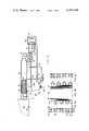
- FIG. 1is a schematic representation of the subject heat pump system, showing both first and second refrigerant fluid loops, which are operable in cascade fashion.
- FIG. 2shows the portion of the system operable in a first mode to heat water and cool air supplied to a comfort zone.
- FIG. 3shows the portion of the system, operable in a third mode to heat air supplied to the comfort zone.
- FIGS. 4A, 4B, and 4Cillustrate a preferred embodiment of the tri-fluid (double circuited fin and tube) heat exchanger.
- a first and a second refrigerant fluid loopare shown connected in cascade fashion.
- a first compressor 10is operative to discharge a first refrigerant fluid through first discharge port 11 into a conduit 12 connected to a refrigerant-to-water heat exchanger 13.
- the compressed first refrigerant fluidis condensed as it flows through a condenser coil 14, disposed within heat exchanger 13, thereby heating water which enters through inlet 15. Heated water is withdrawn through hot water line 16, as required for use in the facility in which the heat pump system is installed.
- the condensed first refrigerant fluidleaves heat exchanger 13 as a liquid through conduit 19 which is connected to an expansion valve 20.
- Expansion valve 20throttles the flow of condensed first refrigerant fluid, allowing it to expand as it flows into a conduit 21, so that it is vaporized as it flows through an evaporator coil 23 in tri-fluid heat exchanger 22.
- Vaporized first refrigerant fluidtravels through a conduit 28 back to a first suction port 29 on the first compressor 10.
- Tri-fluid heat exchanger 22is disposed within an air delivery duct 24, in heat exchange relationship with air supplied to a comfort zone 25 during operation of the system in mode 1 (Ref. FIG. 2).
- a centrifugal blower 26provides the airflow through duct 24, drawing in air either from a return air plenum (not shown) or fresh air from outside the building, or supplying a mixture of fresh and return air.
- a compressed second refrigerant fluid supplied through a conduit 30passes through a condenser coil 31, which is also disposed in tri-fluid heat exchanger 22, in heat transfer relationship with evaporator coil 23.
- the second refrigerant fluidis thus condensed and the first refrigerant fluid is vaporized.
- Condensed second refrigerant fluidthereafter passes through a conduit 33 to a liquid suction line subcooler 34 wherein it is cooled at constant pressure, and out through conduit 35.
- a second expansion valve 36throttles the liquid second refrigerant fluid passing through conduit 35, and allows it to expand as it enters a conduit 37.
- the expanding second refrigerant fluidis vaporized by heat transfer with air passing through an outdoor ambient air heat exchanger 38.
- Airflow through the outdoor ambient air heat exchanger 38is provided by a fan 39; in mode 2, airflow through heat exchanger 22 is preferably not provided.
- Vaporized second refrigerant fluidreturns to the subcooler 34 through a conduit 41, is superheated by heat from the condensed second refrigerant fluid, and then returns through a conduit 42 to a suction port 43 on the second compressor 32.
- FIG. 3only the portion of the heat pump system comprising the second refrigerant fluid loop is shown.
- This portion of the circuitis active during operation of the system in mode 3, in which air supplied to comfort zone 25 through duct 24 is heated by condensing second refrigerant fluid in the tri-fluid heat exchanger 22.
- the first compressor 10is de-energized, and the first refrigerant fluid loop is inactive.
- air passing through tri-fluid heat exchanger 22is heated by energy given up due to the condensation of the second refrigerant fluid passing through condenser coils 31. Operation of the second refrigerant fluid loop is otherwise the same in mode 3 as in mode 2.
- Control 18is provided with inputs from a water temperature sensor 17 disposed within refrigerant-to-water heat exchanger 13, and a comfort zone temperature sensor 27. Sensors 17 and 27 are connected to control 18 by leads 17a and 27a, respectively. Control leads 10a, 26a, and 32a likewise connect the control 18 with the first compressor 10, the centrifugal fan 26, and the second compressor 32, respectively. Control 18 is operative to energize first compressor 10 and centrifugal fan 26 in the first mode, if water temperature sensor 17 and comfort zone temperature sensor 27 indicate a concurrent demand for hot water and cooling in the comfort zone.
- comfort zone 25Since it is intended that the subject heat pump system primarily provide hot water and only supplemental heating and cooling in comfort zone 25, control 18 does not effect the first mode of operation to cool the comfort zone 25 unless there is also a demand for heating water in the refrigerant-to-water heat exchanger 13. Therefore, it is expected that comfort zone 25 would have other primary means for temperature conditioning, and not depend solely upon the water heating heat pump system for this purpose.
- comfort zone 25should not require a supply of cooled air during periods of the year when the outdoor ambient temperature is relatively low. It is also during such periods of low outdoor ambient air temperature that a conventional single stage heat pump system is incapable of meeting a demand for heating water or heating a comfort zone using energy extracted from the relatively cold air. Under these circumstances, control 18 is operative to effect operation of the heat pump system in either modes 2 or 3. Control 18 effects mode 2 in response to a demand for water heating determined by sensor 17 when there is not a concurrent demand for cooling as determined by comfort zone temperature sensor 27. It should be clear, that control 18 will effect mode 1 instead of mode 2 if there is a demand for cooling in comfort zone 25 regardless of the outdoor ambient air temperature.
- control 18may effect mode 3, energizing second compressor 32 and centrifugal blower 26 to heat air supplied to comfort zone 25, in response to a demand for heat in the comfort zone.
- mode 3energizing second compressor 32 and centrifugal blower 26 to heat air supplied to comfort zone 25, in response to a demand for heat in the comfort zone.
- control 18terminates mode 3 and effects mode 2.
- mode 2control 18 energizes first and second compressors 10 and 32, but normally does not energize blower 26.
- first and second refrigerant fluidsfor use in the heat pump system. These include the range of outdoor ambient air temperatures from which the system is expected to extract energy for heating air and water, and the maximum temperature to which the water is to be heated. Although other refrigerant fluids might be used, in the preferred embodiment, it is expected that the first refrigerant fluid would be selected from the group consisting of refrigerant 12 and refrigerant 22 (Dichlorodifluoromethane R-12, and Chlorodifluoromethane R-22), and that the second refrigerant fluid used in the second or low temperature loop would be selected from the group consisting of refrigerant 13B1, refrigerant 32, refrigerant 502, and refrigerant 504 (Bromotrifluoromethane R-13B1; Methylene Fluoride R-32; an azeotrope of R-22 and Chloropentafluoroethane R-502; and an azeotrope of Methylene Fluoride and
- the group of refrigerants from which the second refrigerant fluid is selectedshould have a relatively high gas density for operation at relatively low ambient temperatures, thus permitting the use of a relatively small displacement second compressor 32.
- the second refrigerant fluidshould have a vapor pressure at temperatures corresponding to high outdoor ambient which is sufficiently low so that specially designed high pressure components are not required.
- R-13B1, R-32, R-502, and R-504all meet these requirements.
- a tube and fin heat exchanger circuited in a manner suitable for use as the tri-fluid heat exchanger 22having common fin material 47 extending between first refrigerant fluid evaporator coils 23 and second refrigerant fluid condenser coils 31.
- the common fin material 47not only provides heat transfer between coils 23 and 31 but also defines air passages through heat exchanger 22 through which air supplied to comfort zone 25 may pass in heat transfer relationship with the first or second refrigerant fluid.
- coils 23 and 31alternate across the face of heat exchangers 22, with ends of each coil separately connected by means of a plurality of U-bends, at each side. Airflow passes through heat exchanger 22 in a direction normal to the surface exposed in FIG. 4B, that surface being oriented transverse to the longitudinal axis of duct 24.
- the cross-sectional area required for tri-fluid heat exchanger 22may exceed that available in duct 24.
- An enlarged ductmay be provided for mounting heat exchanger 22, or a dual circuited heat exchanger of smaller cross-sectional area, having more than two rows of tubes may be used.
- ambient airserves as a source of energy for heating water, or air supplied to comfort zone 25; yet other sources of heat energy might also be used, including ground water from lakes, ponds, or wells, or waste energy available from industrial processes. Minor modifications may also be made to the system, as for example, capillary tubes may be used in place of expansion valves 20 and 36. While the subject invention has been described with respect to the preferred embodiment, it is to be understood that these and further modifications thereto would be apparent to those skilled in the art, which modifications lie within the scope of the present invention as defined in the claims which follow.
Landscapes
- Engineering & Computer Science (AREA)
- Physics & Mathematics (AREA)
- Mechanical Engineering (AREA)
- Thermal Sciences (AREA)
- General Engineering & Computer Science (AREA)
- Chemical & Material Sciences (AREA)
- Combustion & Propulsion (AREA)
- Other Air-Conditioning Systems (AREA)
- Compression-Type Refrigeration Machines With Reversible Cycles (AREA)
Abstract
Description
Claims (15)
Priority Applications (4)
| Application Number | Priority Date | Filing Date | Title |
|---|---|---|---|
| US06/339,540US4391104A (en) | 1982-01-15 | 1982-01-15 | Cascade heat pump for heating water and for cooling or heating a comfort zone |
| CA000417758ACA1175251A (en) | 1982-01-15 | 1982-12-15 | Cascade heat pump for heating water and for cooling or heating a comfort zone |
| DE3301506ADE3301506A1 (en) | 1982-01-15 | 1983-01-14 | HEAT PUMP |
| FR8300544AFR2520095B1 (en) | 1982-01-15 | 1983-01-14 | HEAT PUMP SYSTEM AND METHOD FOR SELECTIVELY HEATING WATER AND HEATING OR COOLING AIR |
Applications Claiming Priority (1)
| Application Number | Priority Date | Filing Date | Title |
|---|---|---|---|
| US06/339,540US4391104A (en) | 1982-01-15 | 1982-01-15 | Cascade heat pump for heating water and for cooling or heating a comfort zone |
Publications (1)
| Publication Number | Publication Date |
|---|---|
| US4391104Atrue US4391104A (en) | 1983-07-05 |
Family
ID=23329502
Family Applications (1)
| Application Number | Title | Priority Date | Filing Date |
|---|---|---|---|
| US06/339,540Expired - Fee RelatedUS4391104A (en) | 1982-01-15 | 1982-01-15 | Cascade heat pump for heating water and for cooling or heating a comfort zone |
Country Status (4)
| Country | Link |
|---|---|
| US (1) | US4391104A (en) |
| CA (1) | CA1175251A (en) |
| DE (1) | DE3301506A1 (en) |
| FR (1) | FR2520095B1 (en) |
Cited By (45)
| Publication number | Priority date | Publication date | Assignee | Title |
|---|---|---|---|---|
| US4507938A (en)* | 1982-09-10 | 1985-04-02 | Mitsubishi Denki Kabushiki Kaisha | System for air-conditioning and hot water supplying |
| US4783223A (en)* | 1985-04-04 | 1988-11-08 | Holstein & Kappert Gmbh | Method of and an arrangement for reducing heat consumption of bottle cleaning machines |
| EP0431760A3 (en)* | 1989-11-24 | 1992-02-26 | Union Kogyo Kabushiki Kaisha | A method for air conditioning and supplying hot/cold water |
| US5305614A (en)* | 1991-10-30 | 1994-04-26 | Lennox Industries Inc. | Ancillary heat pump apparatus for producing domestic hot water |
| US5351502A (en)* | 1991-10-30 | 1994-10-04 | Lennox Industries, Inc. | Combination ancillary heat pump for producing domestic hot h20 with multimodal dehumidification apparatus |
| US5984198A (en)* | 1997-06-09 | 1999-11-16 | Lennox Manufacturing Inc. | Heat pump apparatus for heating liquid |
| US5992160A (en)* | 1998-05-11 | 1999-11-30 | Carrier Corporation | Make-up air energy recovery ventilator |
| US6006541A (en)* | 1993-06-07 | 1999-12-28 | Taylor; Christopher | Refrigeration efficiency improvement by reducing the difference between temperatures of heat rejection and heat absorption |
| US6516623B1 (en)* | 2002-05-07 | 2003-02-11 | Modine Manufacturing Company | Vehicular heat pump system and module therefor |
| WO2003073020A1 (en)* | 2002-02-26 | 2003-09-04 | Kolar Jaroslav | Method for operating a heat pump, and heat pump for carrying out this method |
| EP1072453A3 (en)* | 1999-07-26 | 2003-09-10 | Denso Corporation | Refrigeration-cycle device |
| US6669102B1 (en)* | 2002-12-05 | 2003-12-30 | Lg Electronics Inc. | Method for operating air conditioner in warming mode |
| US20040031858A1 (en)* | 2001-07-16 | 2004-02-19 | International Thermal Investments Ltd. | Potable water heater and method of using same |
| EP1394482A3 (en)* | 2002-08-30 | 2005-05-25 | KKW Kulmbacher Klimageräte-Werk GmbH | Heat pump system |
| US20060277940A1 (en)* | 2005-06-09 | 2006-12-14 | Lg Electronic Inc. | Air conditioner |
| US20070144201A1 (en)* | 2005-12-28 | 2007-06-28 | Sanden Corporation | Air conditioning systems for vehicles |
| US20070251248A1 (en)* | 2005-06-09 | 2007-11-01 | Lg Electronics Inc | Air conditioner |
| US20070271936A1 (en)* | 2003-11-28 | 2007-11-29 | Shinichi Wakamoto | Refrigerator and Air Conditioner |
| US20090107656A1 (en)* | 2007-10-31 | 2009-04-30 | Thermodynamique Solutions Inc. | Heat exchanger |
| US20090211282A1 (en)* | 2004-07-01 | 2009-08-27 | Daikin Industries, Ltd. | Hot water supply system |
| US20100038441A1 (en)* | 2006-08-31 | 2010-02-18 | Troels Pedersen | Energy system with a heat pump |
| US20100043483A1 (en)* | 2006-07-26 | 2010-02-25 | Jacobi Robert W | Thermal storage unit for air conditioning applications |
| US20100077788A1 (en)* | 2008-09-26 | 2010-04-01 | Nyle Special Products, Llc | Cascading air-source heat pump |
| US20100083691A1 (en)* | 2008-10-08 | 2010-04-08 | Venturedyne, Ltd. | Refrigeration capacity banking for thermal cycling |
| GB2475693A (en)* | 2009-11-26 | 2011-06-01 | Smith S Environmental Products Ltd | A heat pump cabinet especially for use with small domestic houses or apartments |
| US20120090559A1 (en)* | 2010-09-30 | 2012-04-19 | Song Yan | Economically-operated, dual-energy hot water supply system and method of operating the same |
| GB2486646A (en)* | 2010-12-20 | 2012-06-27 | Sublogic Mfg Ltd | Method and Apparatus for Cascade Refrigeration and for Central Heating Hot Water Supply |
| US20120180511A1 (en)* | 2009-07-08 | 2012-07-19 | Colipu A/S | Energy System With A Heat Pump |
| US20120192582A1 (en)* | 2010-12-30 | 2012-08-02 | Woo Hyoungsuk | Heat pump interoperating hot water feeding apparatus |
| WO2013006397A3 (en)* | 2011-07-07 | 2013-09-12 | General Electric Company | Hybrid electric water heater with external discharge ducting |
| US20140230479A1 (en)* | 2011-10-28 | 2014-08-21 | Mitsubishi Electric Corporation | Refrigeration and air-conditioning apparatus and humidity control device |
| WO2014160514A3 (en)* | 2013-03-13 | 2015-11-26 | Rheem Manufacturing Company | Apparatus and methods for heating water with refrigerant from air conditioning system |
| US20160097571A1 (en)* | 2013-05-24 | 2016-04-07 | Siemens Aktiengesellschaft | Energy storage system for increasing the flexibility of power plants |
| US9915436B1 (en) | 2015-01-20 | 2018-03-13 | Ralph Feria | Heat source optimization system |
| US9945587B2 (en) | 2014-09-02 | 2018-04-17 | Rheem Manufacturing Company | Apparatus and method for hybrid water heating and air cooling and control thereof |
| WO2019058360A1 (en) | 2017-09-24 | 2019-03-28 | N. A. M. Technology Ltd. | Combined-type cascade refrigerating apparatus |
| US20190242657A1 (en)* | 2018-02-05 | 2019-08-08 | Emerson Climate Technologies, Inc. | Climate-Control System Having Thermal Storage Tank |
| US10458678B2 (en) | 2016-07-06 | 2019-10-29 | Rheem Manufacturing Company | Apparatus and methods for heating water with refrigerant and phase change material |
| US20190346187A1 (en)* | 2018-05-11 | 2019-11-14 | Mitsubishi Electric Us, Inc. | System and method for providing supplemental heat to a refrigerant in an air-conditioner |
| US11067317B2 (en) | 2015-01-20 | 2021-07-20 | Ralph Feria | Heat source optimization system |
| US11149971B2 (en) | 2018-02-23 | 2021-10-19 | Emerson Climate Technologies, Inc. | Climate-control system with thermal storage device |
| US11231205B2 (en) | 2015-12-08 | 2022-01-25 | Trane International Inc. | Using heat recovered from heat source to obtain high temperature hot water |
| US11346583B2 (en)* | 2018-06-27 | 2022-05-31 | Emerson Climate Technologies, Inc. | Climate-control system having vapor-injection compressors |
| US11353227B2 (en)* | 2016-06-16 | 2022-06-07 | Fläktgroup Sweden Ab | Method and device for reducing or eliminating the temperature drop of the supply air temperature during defrosting of an evaporator at an air handling unit |
| US12173909B2 (en) | 2020-07-13 | 2024-12-24 | Rheem Manufacturing Company | Integrated space conditioning and water heating/cooling systems and methods thereto |
Families Citing this family (1)
| Publication number | Priority date | Publication date | Assignee | Title |
|---|---|---|---|---|
| DE102008047753B4 (en) | 2008-09-17 | 2015-10-08 | Konvekta Ag | Refrigeration system with cooling circuits coupled by cascade heat exchanger |
Citations (5)
| Publication number | Priority date | Publication date | Assignee | Title |
|---|---|---|---|---|
| US2204394A (en)* | 1936-03-21 | 1940-06-11 | Gen Electric | Air conditioning system |
| US3301002A (en)* | 1965-04-26 | 1967-01-31 | Carrier Corp | Conditioning apparatus |
| US3984050A (en)* | 1974-04-18 | 1976-10-05 | Projectus Industriprodukter Ab | Heat pump system |
| US4149389A (en)* | 1978-03-06 | 1979-04-17 | The Trane Company | Heat pump system selectively operable in a cascade mode and method of operation |
| US4325226A (en)* | 1981-02-18 | 1982-04-20 | Frick Company | Refrigeration system condenser heat recovery at higher temperature than normal condensing temperature |
Family Cites Families (3)
| Publication number | Priority date | Publication date | Assignee | Title |
|---|---|---|---|---|
| US3392541A (en)* | 1967-02-06 | 1968-07-16 | Larkin Coils Inc | Plural compressor reverse cycle refrigeration or heat pump system |
| DE2705316A1 (en)* | 1977-02-09 | 1978-08-10 | Sundstrand Deutschland Gmbh | HEAT EXCHANGE SYSTEM |
| DE2940079A1 (en)* | 1979-10-03 | 1981-04-16 | Robert Bosch Gmbh, 7000 Stuttgart | Heating plant with two or more heat pumps - has first pump linked to vaporiser of second pump and coolant circuit for output control |
- 1982
- 1982-01-15USUS06/339,540patent/US4391104A/ennot_activeExpired - Fee Related
- 1982-12-15CACA000417758Apatent/CA1175251A/ennot_activeExpired
- 1983
- 1983-01-14DEDE3301506Apatent/DE3301506A1/ennot_activeWithdrawn
- 1983-01-14FRFR8300544Apatent/FR2520095B1/ennot_activeExpired
Patent Citations (5)
| Publication number | Priority date | Publication date | Assignee | Title |
|---|---|---|---|---|
| US2204394A (en)* | 1936-03-21 | 1940-06-11 | Gen Electric | Air conditioning system |
| US3301002A (en)* | 1965-04-26 | 1967-01-31 | Carrier Corp | Conditioning apparatus |
| US3984050A (en)* | 1974-04-18 | 1976-10-05 | Projectus Industriprodukter Ab | Heat pump system |
| US4149389A (en)* | 1978-03-06 | 1979-04-17 | The Trane Company | Heat pump system selectively operable in a cascade mode and method of operation |
| US4325226A (en)* | 1981-02-18 | 1982-04-20 | Frick Company | Refrigeration system condenser heat recovery at higher temperature than normal condensing temperature |
Cited By (71)
| Publication number | Priority date | Publication date | Assignee | Title |
|---|---|---|---|---|
| US4507938A (en)* | 1982-09-10 | 1985-04-02 | Mitsubishi Denki Kabushiki Kaisha | System for air-conditioning and hot water supplying |
| US4783223A (en)* | 1985-04-04 | 1988-11-08 | Holstein & Kappert Gmbh | Method of and an arrangement for reducing heat consumption of bottle cleaning machines |
| EP0431760A3 (en)* | 1989-11-24 | 1992-02-26 | Union Kogyo Kabushiki Kaisha | A method for air conditioning and supplying hot/cold water |
| US5305614A (en)* | 1991-10-30 | 1994-04-26 | Lennox Industries Inc. | Ancillary heat pump apparatus for producing domestic hot water |
| US5351502A (en)* | 1991-10-30 | 1994-10-04 | Lennox Industries, Inc. | Combination ancillary heat pump for producing domestic hot h20 with multimodal dehumidification apparatus |
| US6006541A (en)* | 1993-06-07 | 1999-12-28 | Taylor; Christopher | Refrigeration efficiency improvement by reducing the difference between temperatures of heat rejection and heat absorption |
| US5984198A (en)* | 1997-06-09 | 1999-11-16 | Lennox Manufacturing Inc. | Heat pump apparatus for heating liquid |
| US5992160A (en)* | 1998-05-11 | 1999-11-30 | Carrier Corporation | Make-up air energy recovery ventilator |
| EP1072453A3 (en)* | 1999-07-26 | 2003-09-10 | Denso Corporation | Refrigeration-cycle device |
| US20040031858A1 (en)* | 2001-07-16 | 2004-02-19 | International Thermal Investments Ltd. | Potable water heater and method of using same |
| US7036746B2 (en)* | 2001-07-16 | 2006-05-02 | International Thermal Investments Ltd. | Potable water heater and method of using same |
| WO2003073020A1 (en)* | 2002-02-26 | 2003-09-04 | Kolar Jaroslav | Method for operating a heat pump, and heat pump for carrying out this method |
| US6516623B1 (en)* | 2002-05-07 | 2003-02-11 | Modine Manufacturing Company | Vehicular heat pump system and module therefor |
| EP1394482A3 (en)* | 2002-08-30 | 2005-05-25 | KKW Kulmbacher Klimageräte-Werk GmbH | Heat pump system |
| US6669102B1 (en)* | 2002-12-05 | 2003-12-30 | Lg Electronics Inc. | Method for operating air conditioner in warming mode |
| US20070271936A1 (en)* | 2003-11-28 | 2007-11-29 | Shinichi Wakamoto | Refrigerator and Air Conditioner |
| US7752857B2 (en) | 2003-11-28 | 2010-07-13 | Mitsubishi Denki Kabushiki Kaisha | Refrigerator and air conditioner |
| US7526924B2 (en)* | 2003-11-28 | 2009-05-05 | Mitsubishi Denki Kabushiki Kaisha | Refrigerator and air conditioner |
| US20090158761A1 (en)* | 2003-11-28 | 2009-06-25 | Mitsubishi Denki Kabushiki Kaisha | Refrigerator and air conditioner |
| US20090211282A1 (en)* | 2004-07-01 | 2009-08-27 | Daikin Industries, Ltd. | Hot water supply system |
| US7640763B2 (en)* | 2004-07-01 | 2010-01-05 | Daikin Industries, Ltd. | Hot water supply system |
| US7703296B2 (en)* | 2005-06-09 | 2010-04-27 | Lg Electronics Inc. | Dual cooling mode air conditioner for normal or rapid cooling |
| US20060277940A1 (en)* | 2005-06-09 | 2006-12-14 | Lg Electronic Inc. | Air conditioner |
| US20070251248A1 (en)* | 2005-06-09 | 2007-11-01 | Lg Electronics Inc | Air conditioner |
| US20070144201A1 (en)* | 2005-12-28 | 2007-06-28 | Sanden Corporation | Air conditioning systems for vehicles |
| US20100043483A1 (en)* | 2006-07-26 | 2010-02-25 | Jacobi Robert W | Thermal storage unit for air conditioning applications |
| US7954336B2 (en)* | 2006-07-26 | 2011-06-07 | Jacobi Robert W | Thermal storage unit for air conditioning applications |
| US20100038441A1 (en)* | 2006-08-31 | 2010-02-18 | Troels Pedersen | Energy system with a heat pump |
| US20090107656A1 (en)* | 2007-10-31 | 2009-04-30 | Thermodynamique Solutions Inc. | Heat exchanger |
| US8161765B2 (en) | 2007-10-31 | 2012-04-24 | Thermodynamique Solutions Inc. | Heat exchange system with two single closed loops |
| US20100077788A1 (en)* | 2008-09-26 | 2010-04-01 | Nyle Special Products, Llc | Cascading air-source heat pump |
| US8312734B2 (en) | 2008-09-26 | 2012-11-20 | Lewis Donald C | Cascading air-source heat pump |
| US8166773B2 (en)* | 2008-10-08 | 2012-05-01 | Venturedyne, Ltd. | Refrigeration capacity banking for thermal cycling |
| US20100083691A1 (en)* | 2008-10-08 | 2010-04-08 | Venturedyne, Ltd. | Refrigeration capacity banking for thermal cycling |
| US9016079B2 (en)* | 2009-07-08 | 2015-04-28 | Heatf A/S | Energy system with a heat pump |
| US20120180511A1 (en)* | 2009-07-08 | 2012-07-19 | Colipu A/S | Energy System With A Heat Pump |
| GB2475693A (en)* | 2009-11-26 | 2011-06-01 | Smith S Environmental Products Ltd | A heat pump cabinet especially for use with small domestic houses or apartments |
| US9416980B2 (en)* | 2010-09-30 | 2016-08-16 | A. O. Smith Corporation | Economically-operated, dual-energy hot water supply system and method of operating the same |
| US20120090559A1 (en)* | 2010-09-30 | 2012-04-19 | Song Yan | Economically-operated, dual-energy hot water supply system and method of operating the same |
| GB2486646A (en)* | 2010-12-20 | 2012-06-27 | Sublogic Mfg Ltd | Method and Apparatus for Cascade Refrigeration and for Central Heating Hot Water Supply |
| US20120192582A1 (en)* | 2010-12-30 | 2012-08-02 | Woo Hyoungsuk | Heat pump interoperating hot water feeding apparatus |
| US8950204B2 (en)* | 2010-12-30 | 2015-02-10 | Lg Electronics Inc. | Heat pump interoperating hot water feeding apparatus |
| WO2013006397A3 (en)* | 2011-07-07 | 2013-09-12 | General Electric Company | Hybrid electric water heater with external discharge ducting |
| US9206995B2 (en) | 2011-07-07 | 2015-12-08 | General Electric Company | Hybrid electric water heater with external discharge ducting |
| US20140230479A1 (en)* | 2011-10-28 | 2014-08-21 | Mitsubishi Electric Corporation | Refrigeration and air-conditioning apparatus and humidity control device |
| US9651282B2 (en)* | 2011-10-28 | 2017-05-16 | Mitsubishi Electric Corporation | Refrigeration and air-conditioning apparatus and humidity control device |
| CN108088114B (en)* | 2013-03-13 | 2020-08-21 | 瑞美制造公司 | Apparatus and method for heating water using refrigerant from air conditioning system |
| US12203683B2 (en) | 2013-03-13 | 2025-01-21 | Rheem Manufacturing Company | Apparatus and methods for heating water with refrigerant from air conditioning system |
| US10871307B2 (en) | 2013-03-13 | 2020-12-22 | Rheem Manufacturing Company | Apparatus and methods for heating water with refrigerant from air conditioning system |
| CN105518397B (en)* | 2013-03-13 | 2017-12-26 | 瑞美制造公司 | Apparatus and method for heating water using refrigerant from an air conditioning system |
| US9879881B2 (en) | 2013-03-13 | 2018-01-30 | Rheem Manufacturing Company | Apparatus and methods for heating water with refrigerant from air conditioning system |
| CN105518397A (en)* | 2013-03-13 | 2016-04-20 | 瑞美制造公司 | Apparatus and method for heating water using refrigerant from an air conditioning system |
| US9945582B2 (en) | 2013-03-13 | 2018-04-17 | Rheem Manufacturing Company | Apparatus and methods for pre-heating water with air conditioning unit or heat pump |
| WO2014160514A3 (en)* | 2013-03-13 | 2015-11-26 | Rheem Manufacturing Company | Apparatus and methods for heating water with refrigerant from air conditioning system |
| CN108088114A (en)* | 2013-03-13 | 2018-05-29 | 瑞美制造公司 | Using the apparatus and method of the refrigerant heat water from air handling system |
| US20160097571A1 (en)* | 2013-05-24 | 2016-04-07 | Siemens Aktiengesellschaft | Energy storage system for increasing the flexibility of power plants |
| US10041702B2 (en) | 2014-09-02 | 2018-08-07 | Rheem Manufacturing Company | Apparatus and method for hybrid water heating and air cooling and control thereof |
| US9945587B2 (en) | 2014-09-02 | 2018-04-17 | Rheem Manufacturing Company | Apparatus and method for hybrid water heating and air cooling and control thereof |
| US9915436B1 (en) | 2015-01-20 | 2018-03-13 | Ralph Feria | Heat source optimization system |
| US11067317B2 (en) | 2015-01-20 | 2021-07-20 | Ralph Feria | Heat source optimization system |
| US11231205B2 (en) | 2015-12-08 | 2022-01-25 | Trane International Inc. | Using heat recovered from heat source to obtain high temperature hot water |
| US11353227B2 (en)* | 2016-06-16 | 2022-06-07 | Fläktgroup Sweden Ab | Method and device for reducing or eliminating the temperature drop of the supply air temperature during defrosting of an evaporator at an air handling unit |
| US10458678B2 (en) | 2016-07-06 | 2019-10-29 | Rheem Manufacturing Company | Apparatus and methods for heating water with refrigerant and phase change material |
| WO2019058360A1 (en) | 2017-09-24 | 2019-03-28 | N. A. M. Technology Ltd. | Combined-type cascade refrigerating apparatus |
| US20190242657A1 (en)* | 2018-02-05 | 2019-08-08 | Emerson Climate Technologies, Inc. | Climate-Control System Having Thermal Storage Tank |
| US11585608B2 (en)* | 2018-02-05 | 2023-02-21 | Emerson Climate Technologies, Inc. | Climate-control system having thermal storage tank |
| US11149971B2 (en) | 2018-02-23 | 2021-10-19 | Emerson Climate Technologies, Inc. | Climate-control system with thermal storage device |
| US20190346187A1 (en)* | 2018-05-11 | 2019-11-14 | Mitsubishi Electric Us, Inc. | System and method for providing supplemental heat to a refrigerant in an air-conditioner |
| US10941965B2 (en)* | 2018-05-11 | 2021-03-09 | Mitsubishi Electric Us, Inc. | System and method for providing supplemental heat to a refrigerant in an air-conditioner |
| US11346583B2 (en)* | 2018-06-27 | 2022-05-31 | Emerson Climate Technologies, Inc. | Climate-control system having vapor-injection compressors |
| US12173909B2 (en) | 2020-07-13 | 2024-12-24 | Rheem Manufacturing Company | Integrated space conditioning and water heating/cooling systems and methods thereto |
Also Published As
| Publication number | Publication date |
|---|---|
| FR2520095B1 (en) | 1987-04-24 |
| DE3301506A1 (en) | 1983-07-28 |
| CA1175251A (en) | 1984-10-02 |
| FR2520095A1 (en) | 1983-07-22 |
Similar Documents
| Publication | Publication Date | Title |
|---|---|---|
| US4391104A (en) | Cascade heat pump for heating water and for cooling or heating a comfort zone | |
| US4336692A (en) | Dual source heat pump | |
| US4308042A (en) | Heat pump with freeze-up prevention | |
| CA1068919A (en) | Heat pump system selectively operable in a cascade mode and method of operation | |
| KR0132344B1 (en) | Manual defrosting system using waste heat and manual defrosting method and heat pump | |
| US4633676A (en) | Cooling and heating apparatus | |
| JP2554208B2 (en) | Heat pump water heater | |
| US5689962A (en) | Heat pump systems and methods incorporating subcoolers for conditioning air | |
| US5771700A (en) | Heat pump apparatus and related methods providing enhanced refrigerant flow control | |
| CA1179160A (en) | Control system for duo heat pump | |
| US4688396A (en) | Air-conditioning hot-water supply device | |
| US7210303B2 (en) | Transcritical heat pump water heating system using auxiliary electric heater | |
| KR19990067577A (en) | Heat energy storage air conditioner | |
| CA1189703A (en) | Climatic control system | |
| JPH0333984B2 (en) | ||
| JP2002310519A (en) | Heat pump water heater | |
| US4612782A (en) | Twin reservoir heat transfer circuit | |
| JP2002310497A (en) | Heat pump water heater | |
| JP3475293B2 (en) | Heat pump water heater | |
| CN108224841A (en) | A kind of heat pump system with drip tray ice-melt pipeline | |
| EP1676080A1 (en) | Hot-water production system of heat pump type | |
| KR100419480B1 (en) | Multi heat pump system with advanced heating and cooling performance | |
| JPS6342188B2 (en) | ||
| JPS5918359A (en) | Air-conditioning hot-water supply device | |
| JPH03211374A (en) | Air conditioning/heating water heater and its control method |
Legal Events
| Date | Code | Title | Description |
|---|---|---|---|
| AS | Assignment | Owner name:TRANE COMPANY,THE, LA CROSSE, WIS. A CORP. OF WIS. Free format text:ASSIGNMENT OF ASSIGNORS INTEREST.;ASSIGNOR:WENDSCHLAG, JAMES C.;REEL/FRAME:003965/0618 Effective date:19820113 | |
| AS | Assignment | Owner name:TRANE COMPANY, THE Free format text:MERGER;ASSIGNOR:A-S CAPITAL INC. A CORP OF DE;REEL/FRAME:004334/0523 | |
| AS | Assignment | Owner name:TRANE COMPANY THE Free format text:MERGER;ASSIGNORS:TRANE COMPANY THE, A CORP OF WI (INTO);A-S CAPITAL INC., A CORP OF DE (CHANGED TO);REEL/FRAME:004372/0370 Effective date:19840224 Owner name:AMERICAN STANDARD INC., A CORP OF DE Free format text:MERGER;ASSIGNORS:TRANE COMPANY, THE;A-S SALEM INC., A CORP. OF DE (MERGED INTO);REEL/FRAME:004372/0349 Effective date:19841226 | |
| MAFP | Maintenance fee payment | Free format text:PAYMENT OF MAINTENANCE FEE, 4TH YEAR, PL 96-517 (ORIGINAL EVENT CODE: M170); ENTITY STATUS OF PATENT OWNER: LARGE ENTITY Year of fee payment:4 | |
| AS | Assignment | Owner name:BANKERS TRUST COMPANY Free format text:SECURITY INTEREST;ASSIGNOR:AMERICAN STANDARD INC., A DE. CORP.,;REEL/FRAME:004905/0035 Effective date:19880624 Owner name:BANKERS TRUST COMPANY, 4 ALBANY STREET, 9TH FLOOR, Free format text:SECURITY INTEREST;ASSIGNOR:TRANE AIR CONDITIONING COMPANY, A DE CORP.;REEL/FRAME:004905/0213 Effective date:19880624 Owner name:BANKERS TRUST COMPANY, NEW YORK Free format text:SECURITY INTEREST;ASSIGNOR:TRANE AIR CONDITIONING COMPANY, A DE CORP.;REEL/FRAME:004905/0213 Effective date:19880624 | |
| MAFP | Maintenance fee payment | Free format text:PAYMENT OF MAINTENANCE FEE, 8TH YEAR, PL 96-517 (ORIGINAL EVENT CODE: M171); ENTITY STATUS OF PATENT OWNER: LARGE ENTITY Year of fee payment:8 | |
| AS | Assignment | Owner name:CHEMICAL BANK, AS COLLATERAL AGENT, NEW YORK Free format text:ASSIGNMENT OF SECURITY INTEREST;ASSIGNOR:BANKERS TRUST COMPANY, AS COLLATERAL TRUSTEE;REEL/FRAME:006565/0753 Effective date:19930601 Owner name:CHEMICAL BANK, AS COLLATERAL AGENT, NEW YORK Free format text:ASSIGNMENT OF ASSIGNORS INTEREST;ASSIGNOR:AMERICAN STANDARD INC.;REEL/FRAME:006566/0170 Effective date:19930601 | |
| FEPP | Fee payment procedure | Free format text:MAINTENANCE FEE REMINDER MAILED (ORIGINAL EVENT CODE: REM.); ENTITY STATUS OF PATENT OWNER: LARGE ENTITY | |
| LAPS | Lapse for failure to pay maintenance fees | ||
| FP | Lapsed due to failure to pay maintenance fee | ||
| AS | Assignment | Owner name:AMERICAN STANDARD, INC., NEW JERSEY Free format text:RELEASE OF SECURITY INTEREST (RE-RECORD TO CORRECT DUPLICATES SUBMITTED BY CUSTOMER. THE NEW SCHEDULE CHANGES THE TOTAL NUMBER OF PROPERTY NUMBERS INVOLVED FROM 1133 TO 794. THIS RELEASE OF SECURITY INTEREST WAS PREVIOUSLY RECORDED AT REEL 8869, FRAME 0001.);ASSIGNOR:CHASE MANHATTAN BANK, THE (FORMERLY KNOWN AS CHEMICAL BANK);REEL/FRAME:009123/0300 Effective date:19970801 | |
| AS | Assignment | Owner name:AMERICAN STANDARD, INC., NEW JERSEY Free format text:RELEASE OF SECURITY INTEREST;ASSIGNOR:CHASE MANHATTAN BANK, THE (FORMERLY KNOWN AS CHEMICAL BANK);REEL/FRAME:008869/0001 Effective date:19970801 | |
| STCH | Information on status: patent discontinuation | Free format text:PATENT EXPIRED DUE TO NONPAYMENT OF MAINTENANCE FEES UNDER 37 CFR 1.362 |