US4390956A - Apparatus for correcting measured gas flow - Google Patents
Apparatus for correcting measured gas flowDownload PDFInfo
- Publication number
- US4390956A US4390956AUS06/241,328US24132881AUS4390956AUS 4390956 AUS4390956 AUS 4390956AUS 24132881 AUS24132881 AUS 24132881AUS 4390956 AUS4390956 AUS 4390956A
- Authority
- US
- United States
- Prior art keywords
- volume
- display
- pressure
- switching element
- temperature
- Prior art date
- Legal status (The legal status is an assumption and is not a legal conclusion. Google has not performed a legal analysis and makes no representation as to the accuracy of the status listed.)
- Expired - Fee Related
Links
- 238000004364calculation methodMethods0.000claimsabstractdescription33
- 239000011159matrix materialSubstances0.000claimsabstractdescription19
- 238000012360testing methodMethods0.000claimsdescription26
- 238000012937correctionMethods0.000claimsdescription14
- 230000004044responseEffects0.000claimsdescription10
- 238000006243chemical reactionMethods0.000claimsdescription4
- 230000003213activating effectEffects0.000claims5
- 230000008878couplingEffects0.000claims2
- 238000010168coupling processMethods0.000claims2
- 238000005859coupling reactionMethods0.000claims2
- 230000002401inhibitory effectEffects0.000claims1
- 238000012544monitoring processMethods0.000claims1
- 230000000007visual effectEffects0.000claims1
- 239000000203mixtureSubstances0.000abstractdescription6
- 230000005484gravityEffects0.000abstractdescription2
- 239000007789gasSubstances0.000description33
- 230000000994depressogenic effectEffects0.000description13
- 230000006870functionEffects0.000description7
- 210000001072colonAnatomy0.000description6
- VNWKTOKETHGBQD-UHFFFAOYSA-NmethaneChemical compoundCVNWKTOKETHGBQD-UHFFFAOYSA-N0.000description6
- 230000000881depressing effectEffects0.000description5
- 238000010586diagramMethods0.000description5
- 238000000034methodMethods0.000description3
- 239000003345natural gasSubstances0.000description3
- 238000005259measurementMethods0.000description2
- 102000003712Complement factor BHuman genes0.000description1
- 108090000056Complement factor BProteins0.000description1
- 240000007320Pinus strobusSpecies0.000description1
- XUIMIQQOPSSXEZ-UHFFFAOYSA-NSiliconChemical compound[Si]XUIMIQQOPSSXEZ-UHFFFAOYSA-N0.000description1
- 230000006978adaptationEffects0.000description1
- 230000002457bidirectional effectEffects0.000description1
- 230000006835compressionEffects0.000description1
- 238000007906compressionMethods0.000description1
- 238000001514detection methodMethods0.000description1
- 239000002737fuel gasSubstances0.000description1
- 229930195733hydrocarbonNatural products0.000description1
- 150000002430hydrocarbonsChemical class0.000description1
- 238000005293physical lawMethods0.000description1
- 238000011160researchMethods0.000description1
- 239000000523sampleSubstances0.000description1
- 239000004065semiconductorSubstances0.000description1
- 229910052710siliconInorganic materials0.000description1
- 239000010703siliconSubstances0.000description1
- 239000007787solidSubstances0.000description1
- 229910001220stainless steelInorganic materials0.000description1
- 239000010935stainless steelSubstances0.000description1
Images


Classifications
- G—PHYSICS
- G01—MEASURING; TESTING
- G01F—MEASURING VOLUME, VOLUME FLOW, MASS FLOW OR LIQUID LEVEL; METERING BY VOLUME
- G01F15/00—Details of, or accessories for, apparatus of groups G01F1/00 - G01F13/00 insofar as such details or appliances are not adapted to particular types of such apparatus
- G01F15/07—Integration to give total flow, e.g. using mechanically-operated integrating mechanism
- G01F15/075—Integration to give total flow, e.g. using mechanically-operated integrating mechanism using electrically-operated integrating means
- G01F15/0755—Integration to give total flow, e.g. using mechanically-operated integrating mechanism using electrically-operated integrating means involving digital counting
- G—PHYSICS
- G01—MEASURING; TESTING
- G01F—MEASURING VOLUME, VOLUME FLOW, MASS FLOW OR LIQUID LEVEL; METERING BY VOLUME
- G01F15/00—Details of, or accessories for, apparatus of groups G01F1/00 - G01F13/00 insofar as such details or appliances are not adapted to particular types of such apparatus
- G01F15/02—Compensating or correcting for variations in pressure, density or temperature
- G01F15/04—Compensating or correcting for variations in pressure, density or temperature of gases to be measured
- G01F15/043—Compensating or correcting for variations in pressure, density or temperature of gases to be measured using electrical means
- G01F15/046—Compensating or correcting for variations in pressure, density or temperature of gases to be measured using electrical means involving digital counting
Definitions
- This inventionrelates to gas flow measurements and, more particularly, to the correction of a measured unit volume of gas flowing through a conduit to a base volume at given base conditions of base pressure and base temperature.
- Gasis a compressible item, the volume of which changes as a function of temperature and pressure, in accordance with well known physical laws. Because gas is a compressible commodity, the buyer and seller of this commodity must agree upon the same conditions. Thus, to distribute and sell gas that is exposed to varying conditions of temperature and pressure, calculations must be made to convert the measured gas flow volume V f in terms of cubic feet at varying conditions of temperature T f and pressure P f , to a standard cubic feet volume V b at specified, previously agreed upon base temperature T b and base pressure P b .
- Vis volume
- Wis mass
- Ttemperature
- V fis the measured uncorrected volume
- T bis base temperature in degrees Rankine
- T fis the temperature of the flowing gas in °R
- F pvis the supercompressibility factor which is equal to ##EQU2##
- the difficult part of calculating base volume in accordance with equation (2)is to determine the supercompressibility factor which is a function of the flowing temperature and pressure as well as the specific gravity and the composition of the gas being measured.
- One way of determining the supercompressibility factoris to utilize tables such as those set forth in the "Manual for the Determination of Supercompressibility Factors for Natural Gas", PAR Research Projects NX-19, published by the American Gas Association. However, if it is desired to automate the correction of measured gas flow, it is difficult and expensive to utilize tables. Alternatively, it is possible to utilize a series of equations to calculate the supercompressibility factor.
- 4,173,891discloses such an automated system including a microprocessor for repetitively calculating the supercompressibility factor.
- the method employed by the patented systemincludes a plurality of computing steps for each calculation of the base natural gas flow. During each computing step, an initially approximated value of the supercompressibility factor or the previously calculated value is used to calculate an indication of the base natural gas flow, each computing step being insufficient to recalculate the supercompressibility factor, this calculation taking a plurality of steps. Therefore, the disclosed system has the disadvantage that a relatively large amount of time is required each time the supercompressibility factor is to be calculated. In fact, it requires five input meter pulses for a complete calculation to be performed. Another disadvantage of the system disclosed in this patent is that the calculations are performed utilizing floating point arithmetic, which requires a large amount of memory capacity, increasing the cost of the system hardware.
- the foregoing and additional objectsare attained in accordance with the principles of this invention by providing apparatus for correcting a measured unit volume of gas flowing through a conduit to a base volume at given base conditions of base pressure and base temperature.
- the apparatusincludes temperature and pressure transducers which provide signals corresponding to their measurements of the temperature and pressure, respectively, of the flowing gas.
- a meter connected in the conduitmeasures the uncorrected volume of the flowing gas and provides to the apparatus a volume pulse in response to measuring a unit volume of the gas.
- a set of constants derived from customer supplied data as to base conditions and gas contentare stored in the apparatus on a diode matrix card.
- the stored constants and the measured temperature and pressure valuesare utilized for performing a series of calculations to derive the supercompressibility factor and in turn a corrected volume. All calculations are performed utilizing integer arithmetic, rather than floating point arithmetic, in order to efficiently utilize memory and achieve a cost saving.
- the output of the apparatusis a first counter which indicates the uncorrected volume and a second counter which indicates the corrected volume.
- a test unitwhich may be plugged into the apparatus and is powered thereby. This test unit does not interfere with the operation of the apparatus or the meter.
- the test unitcan be activated to display flowing pressure and temperature, to cancel out of limit indications, to verify system operation and also may be utilized to test the apparatus counter.
- FIG. 1illustrates the mounting of volume corrector apparatus constructed in accordance with the principles of this invention and its relationship to a meter connected in a conduit;
- FIG. 2illustrates a test unit, constructed in accordance with the principles of this invention, which may be plugged into the volume corrector apparatus shown in FIG. 1;
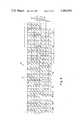
- FIG. 3illustrates a diode matrix board which forms a part of the volume corrector apparatus and is used for storing constants derived from customer supplied data
- FIG. 4is a block diagram of the illustrative volume corrector apparatus and test unit of FIGS. 1, 2 and 3;
- FIG. 5is a flow diagram illustrating the overall system operation of the volume corrector apparatus constructed in accordance with the principles of this invention.
- FIGS. 6 through 11are flow diagrams of subroutines which form a part of the system operation shown in FIG. 5.
- FIG. 1illustrates volume corrector apparatus, designated generally by the reference character 20, mounted on a meter 22 connected in a conduit 24 through which gas flows.
- the meter 22does not form a part of the present invention and may be any type of meter so long as it satisfies the requirement that the corrector 20 needs a low speed input derived from the output register drive shaft of the meter 22.
- the corrector 20may be mounted remotely from the meter 22 and in this case, the input to the corrector 20 will be an electrical switch closure derived from the output register drive shaft of the meter 22, in a manner well known in the art.
- the corrector 20also derives input signals from a temperature transducer 26 and a pressure transducer 28 which extend into the conduit 24.
- the temperature transducer 26is illustratively a model AC2626K temperature transducer manufactured by Analog Devices and is an integrated circuit housed in a stainless steel tubular probe which produces an output current linearly proportional to absolute temperature.
- the pressure transducer 28is illustratively a model ITQH-24 pressure transducer manufactured by Kulite Semiconductor Products and includes a solid state sensing element which is a monolithic integrated circuit Wheatstone bridge directly formed on a silicon diaphragm, and is available in different ranges, depending upon the desired application.
- the output of the pressure transducer 28is a voltage which is related, over the range, to the pressure of the gas flowing through the conduit 24.
- the corrector apparatus 20Since the corrector apparatus 20 is designed for use at remote locations, such as in a desert area, where commercially available power may not be available, the apparatus 20 is designed to be battery operated. Further, a solar battery charger 27 may be provided mounted above the apparatus 20. If the enclosed corrector apparatus 20 were to be exposed to direct sunlight, its interior temperature would rise to an unacceptable level. Therefore, a sunshade 29 is also provided to shield the apparatus 20 from the direct rays of the sun.
- the corrector apparatus 20has as its output two counters.
- a first counter 30is a mechanical counter which displays the uncorrected volume.
- the counter 30is incremented by rotation of the output register drive shaft of the meter 22. If the corrector 20 is not mounted on the meter 22, the uncorrected counter 30 is replaced by the original meter register.
- the second counter 32is the corrected counter and is an electromechanical or electronic counter which displays the corrected volume. It is incremented by signals generated within the corrector 20 in response to inputs from the meter 22 and calculations based upon measured temperature and pressure, in a manner to be described in detail hereinafter.
- the corrector apparatusalso includes a low battery indicator 33.
- FIG. 2illustrates a test unit, denoted generally by the reference numeral 34, which is a portable instrument used in the shop and field to check the operation of the corrector 20.
- the test unit 34includes a cable and connector assembly 36 which plugs into a suitable receptacle, not shown, in the corrector 20. Power for the test unit 34 is obtained from the corrector 20.
- the test unit 34includes a numerical display 38 and a plurality of test buttons 40, 42, 44, 46 and 48.
- the flowing temperaturemay be read directly in °C. or °F. on the display 38 by depressing the button 44.
- the button 46When the button 46 is depressed, the display 38 will display a number which has been determined to be the "signature" of the corrector 20 when it is operating correctly. If the display 38 displayed colons along with numbers when any of the buttons 42, 44 or 46 was depressed, this indicates that some time after the last check was made either the pressure or temperature was out of specified limits. The display of colons will not indicate which parameter was out of limit or if the high or low limit was exceeded. Depressing the button 48 will remove the colons from the display 38 and reset the corrector 20. When the buttons 46 and 48 are depressed simultaneously, the display 38 will display a number indicating the correction multiplier for the presently flowing conditions of pressure and temperature.
- a customerplaces an order for a corrector 20 to be used at a particular location, the customer also specifies certain conditions at that location.
- the customermust specify the type of flowing gas which is to be measured, its composition, the range of pressures at which the gas will flow, and the base temperature and pressure to which the flow volume is to be corrected. These values are utilized to calculate a series of constants which are stored in the corrector 20 for subsequent utilization in making correction calculations.
- C and Scan be expressed as linear equations which are functions of the pressure P f . Then, a form as shown below can be derived:
- K constantsare calculated. These constants K 1 -K 8 are stored within the corrector 20 on a diode matrix card 50 as shown in FIG. 3. Additionally, a constant K 9 which equals 256 (utilized in equations (6) and (7) is stored on the card 50.
- the card 50stores these values in binary coded decimal (BCD) and when voltages are applied to the appropriate leads 52, the leads 54 are selectively energized in a manner well known in the art.
- BCDbinary coded decimal
- the matrix card 50stores the base pressure factor B which equals the atmospheric pressure divided by the base pressure, the maximum gage pressure for which readings are accurate, the range factor R of the pressure transducer 28 which equals the maximum gage pressure divided by the base pressure, the counter multiplier and the base temperature T b .
- These valuesare stored on the diode matrix card 50 by selectively connecting diodes between the leads 52 and the leads 54, as is well known in the art, in a BCD format.
- the diode matrix card 50may be replaced by a programmable ROM.
- Ris the range factor of the pressure transducer 28, which is stored on the diode matrix card 50
- Pis the measured pressure and varies from 0 to 1000 as a linear proportion of the range of the pressure transducer 28
- T bis the base temperature in degrees Rankine, and is stored on the diode matrix card 50
- T fis the flowing temperature in degrees Rankine and equals the temperature measured by the temperature transducer 26 (in degrees Fahrenheit) plue 460
- Bis the base factor and equals the atmospheric pressure divided by the base pressure, this constant being stored on the diode matrix card 50.
- S and Care calculated from equations (6) and (7), utilizing the constants stored on the diode matrix card 50 (depending upon the measured temperature) and the measured pressure. Utilizing the calculated values of S and C, and the measured temperature and pressure, the following equations (12)-(16) are utilized to calculate the supercompressibility factor F pv .
- the foregoing calculationsare performed each time a pulse is received from the meter 22. These calculations are performed utilizing integer arithmetic to avoid the cost of floating point arithmetic. It has been determined that the accuracy of the above calculations is to within ⁇ 0.1% .
- FIG. 4shown therein is an overall block diagram of volume corrector apparatus operating with accordance with the present invention, as described above. All the functions of the volume corrector apparatus shown in FIG. 4 are controlled by a microprocessor 100, illustratively a type 1802 microprocessor manufactured by RCA Corporation.
- the corrector apparatusis battery powered, by battery 102, and in order to reduce quiescent battery drain, the temperature transducer 26 and the pressure transducer 28 are only energized through the power switch 103 when the microprocessor 100 requires inputs therefrom.
- An illustrative arrangement for reducing quiescent battery drainis disclosed in U.S. Pat. No. 4,056,717, and the reader is referred thereto if further details are desired.
- the microprocessor 100Whenever there is a signal at the output of the latch 104, through the control switch 106 to the microprocessor 100, the microprocessor 100 will start its internal program. An output from the latch 104 will occur in response to either a request from the test unit 34 or a meter input switch pulse over the lead 108.
- the meter input switch pulseis generated in response to rotation of the output register drive shaft of the meter 22. Illustratively, that shaft has mounted thereon a small permanent magnet. A switching device located in close proximity to the magnet will provide two pulses over the lead 110 for every complete rotation of the output register drive shaft. Each rotation of the output register drive shaft will also mechanically increment the uncorrected counter 30, in a manner well known in the art.
- the pulses over the lead 110pass through a Schmitt trigger circuit 112 which functions as a squaring and debounce circuit, and then passes to the divide-by-two or divide-by-twenty circuit 114, so that only every other or every twentieth pulse will trigger the one shot circuit 116 to set the latch 104.
- the reason that a divide-by-twenty operation would be requiredis that if a large capacity meter with a ten foot drive is utilized, it is desirable to reduce the number of input pulses to the corrector apparatus in order to conserve the batteries.
- the latch 104is also set by depression of any of the buttons 42, 44 or 46 when the test unit 34 is connected to the corrector 20.
- the microprocessor 100is controlled by a fixed program contained in the ROM 120.
- the RAM 122is used for the temporary storage of variables and calculations. Whenever there is a signal at the output of the latch 104, the microprocessor 100 will start its program. An input meter pulse always has top priority and is always serviced regardless of information being requested by the test unit 34.
- the data bus 124is a bidirectional signal highway from the ROM 120, the RAM 122, the output port 130 and the input port 123, to the microprocessor 100.
- the port select circuit 126receives an output from the microprocessor 100 and directs signals to the input port 128 or the output port 130.
- the data from the temperature transducer 26, the pressure transducer 28 and the diode matrix 50is made available to the microprocessor 100 via the analog-to-digital converter 132.
- the output port 130directs data to the test unit display 38, the corrected counter 32, and strobes the analog-to-digital converter 132 to convert the information on pressure and temperature, as will be described.
- the pressure transducer 28, through the instrument amplifier 134, or the temperature transducer 26,are coupled to the analog-to-digital converter 132 through the multiplexer 136.
- the multiplexer 136outputs either temperature or pressure analog information to the analog-to-digital converter 132 which begins conversion upon receiving a start conversion signal from output port 130.
- the output from the analog-to-digital converter 132is in sequential BCD, as controlled by the strobing from the output port 130 upon receiving a conversion complete signal from converter 132.
- the "signature" of the corrector apparatusis the correction factor obtained by using 50.5% of the full scale value of maximum gage pressure, a temperature of 505° R., and all the values supplied by the customer and converted into the constants on the diode matrix card 50.
- This signatureis calculated and displayed on the display 38 when the test unit 34 is connected to the corrector 20 and the button 46 is depressed. If either the button 42 or the button 44 is depressed, this will cause the microprocessor 100 to be held in either the pressure or temperature mode and display on the display 38 updated information as to the pressure and temperature for as long as either of the buttons 42 or 44 is depressed, unless a meter input pulse occurs.
- the limit detect and hold circuit 140will be set which will cause the display 38 to display colons. If the cancel limit button 48 is depressed, this will reset the limit detect and hold circuit 140, cancelling the display of colons. However, should the over range condition still exist, the limit detect and hold circuit 140 will be reset immediately upon release of the cancel limit button 48 and the display of colons will return. Depressing buttons 46 and 48 simultaneously simulates a meter input pulse. The correction factor is displayed on the test unit display 38 but an output to the corrected counter 32 is inhibited.
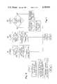
- FIG. 5is a flow diagram illustrating the overall operation of the system described above. This operation is controlled by the microprocessor 100 operating in accordance with a program stored in ROM 120. As shown in FIG. 5, when power is first applied to the corrector apparatus, an initialization routine is performed. The microprocessor 100 then goes into its WSTART (warm start) state where it awaits a signal from the control switch 106 that the latch 104 has been set. When such a signal is recognized the battery condition is checked. If the battery condition is okay then the program continues. If the battery condition is low then the program returns to WSTART and no calculations are performed. As described above, the first priority is an input meter pulse.
- WSTARTwarm start
- the microprocessor 100In the event that the latch 104 was set in response to an input meter pulse, the microprocessor 100 must then collect all the data it requires for a correction calculation. This data is from the temperature transducer 26, the pressure transducer 28 and the constants stored on the diode matrix card 50. This data, which is in Binary Coded Decimal form, is converted to hexadecimal form for calculation purposes. This data is stored in the RAM 122.
- the correction calculationsare next performed.
- the PTCALC subroutine shown in FIG. 6is performed.
- blocks 202, 204 and 206calculate X 1 utilizing equation (8).
- Blocks 208 and 210calculate X 3 utilizing equation (10).
- Blocks 212, 214 and 216calculate X 2 utilizing equation (9).
- blocks 218 and 220calculate X 4 utilizing equation (11).
- the results of this calculationare then stored for later use, as shown by block 222.
- the programthen returns to the main program where the next step is to do the supercompressibility calculation utilizing the FPVCLC subroutine shown in FIG. 7.
- this subroutineit is first determined whether the measured temperature is less than or greater than a given value so that the proper value of i is utilized for equations (6) and (7).
- the CPGAGE subroutine as shown in FIG. 8is utilized to calculate the gage pressure.
- the TYPCLC subroutineis utilized to calculate S, according to equation (6), as shown in FIG. 9.
- Cis calculated utilizing equation (7).
- C 1is calculated utilizing equation (12).
- C 2 and C 3are calculated utilizing equations (13) and (14).
- Utilizing equation (15), C 4is calculated as shown in block 228.
- the COUNT subroutine(FIG. 10) is called to update the corrected counter 32.
- the corrected volume which was calculatedis added to a remainder value from a previous calculation. This sum is then divided by the counter multiplier which results in an integral number of counts plus a new remainder, both of which are stored in the RAM 122. The integral number of counts is then utilized to increment the corrected counter 32. Control is then returned to the main program which remains in the WSTART state awaiting another input pulse from the control switch 106.
- FIG. 11illustrates the subroutines for responding to depression of the buttons 42, 44 and 46.
- the TPRESS subroutineis performed. First, the appropriate data is retrieved from the pressure transducer 28 and the diode matrix card 50 and converted to hexadecimal. The pressure data is then examined to see if it is within the appropriate limits. If so, the CPGAGE subroutine (FIG. 8) is called to calculate the gage pressure. The calculated gage pressure in hexadecimal is then converted to binary coded decimal and displayed on the display 38 of the test unit 34. This is used for calibration and check purposes. The program then returns to the WSTART state.
- the TTEMP subroutine(FIG. 11) is performed. First, the temperature data from the temperature transducer 26 is obtained, converted to hexadecimal, and checked to see whether it is within prescribed limits. Next, the temperature is converted to degrees Fahrenheit and then converted to Binary Coded Decimal, in which form it is displayed on the display 38. This is used for calibration and check purposes. The program then returns to the WSTART state.
- the programcauses the TTEST subroutine (FIG. 11) to be performed.
- datais retrieved from the diode matrix card 50 and in place of temperature and pressure readings, the fixed constant 0505 is placed on data bus 124 via input port 123.
- the calculations set forth in the calculation block of FIG. 5are performed. This should result in a particular "signature" for the volume corrector apparatus. This signature is converted to Binary Coded Decimal and displayed on the display 38. The program then returns to the WSTART state.
- the programcauses the TTEST subroutine (FIG. 11) to be executed.
- detection of simultaneous button pushescauses the program to read the pressure 28 and temperature 26 transducers instead of presenting the fixed number 0505 to the input port 123, and the resulting calculation proceeds according to the calculation block of FIG. 5.
Landscapes
- Physics & Mathematics (AREA)
- Fluid Mechanics (AREA)
- General Physics & Mathematics (AREA)
- Measuring Volume Flow (AREA)
- Details Of Flowmeters (AREA)
- Indication And Recording Devices For Special Purposes And Tariff Metering Devices (AREA)
Abstract
Description
PV=WRTZ (1)
F.sub.pv -1=(P.sub.f /QT.sub.f). (3)
Q=S+CT.sub.f. (5)
S=K.sub.i+1 +K.sub.i (P.sub.f /256) (6)
C=K.sub.i+3 +K.sub.i+2 (P.sub.f /256) (7)
X.sub.1 =RP/1000 (8)
X.sub.2 =1000T.sub.b /T.sub.f (9)
X.sub.3 =X.sub.1 +B (10)
X.sub.4 =X.sub.2 X.sub.3 /1000 (11)
C.sub.1 =CT.sub.f /1000 (12)
C.sub.2 =C.sub.1 +S (13)
C.sub.3 =T.sub.f C.sub.2 /10 (14)
C.sub.4 =10000P.sub.g /C.sub.3 (15)
F.sub.pv =10000+C.sub.4 (16)
F.sub.z =(F.sub.pv).sup.2 /10000 (17)
V.sub.c =X.sub.4 F.sub.z /10000. (18)
V'.sub.c =V.sub.c /M. (19)
Claims (17)
Priority Applications (8)
| Application Number | Priority Date | Filing Date | Title |
|---|---|---|---|
| US06/241,328US4390956A (en) | 1981-03-06 | 1981-03-06 | Apparatus for correcting measured gas flow |
| CA000394508ACA1169561A (en) | 1981-03-06 | 1982-01-20 | Apparatus for correcting measured gas flow |
| GB8202015AGB2094521B (en) | 1981-03-06 | 1982-01-25 | Apparatus for correcting measured gas flow |
| DE19823203781DE3203781A1 (en) | 1981-03-06 | 1982-02-04 | DEVICE FOR CORRECTING A MEASURED UNIT VOLUME OF A GAS TO A BASE VOLUME |
| FR8203017AFR2501365B1 (en) | 1981-03-06 | 1982-02-24 | DEVICE FOR CORRECTING A VOLUME OF MEASURED GAS |
| JP57032972AJPS57158521A (en) | 1981-03-06 | 1982-03-02 | Apparatus for correcting gas flow measured |
| DK98682ADK98682A (en) | 1981-03-06 | 1982-03-05 | DEVICE FOR CORRECTION OF A MEASURED GAS FLOW |
| AU81146/82AAU549340B2 (en) | 1981-03-06 | 1982-03-05 | Temp/press compensation of measured gas flow |
Applications Claiming Priority (1)
| Application Number | Priority Date | Filing Date | Title |
|---|---|---|---|
| US06/241,328US4390956A (en) | 1981-03-06 | 1981-03-06 | Apparatus for correcting measured gas flow |
Publications (1)
| Publication Number | Publication Date |
|---|---|
| US4390956Atrue US4390956A (en) | 1983-06-28 |
Family
ID=22910260
Family Applications (1)
| Application Number | Title | Priority Date | Filing Date |
|---|---|---|---|
| US06/241,328Expired - Fee RelatedUS4390956A (en) | 1981-03-06 | 1981-03-06 | Apparatus for correcting measured gas flow |
Country Status (8)
| Country | Link |
|---|---|
| US (1) | US4390956A (en) |
| JP (1) | JPS57158521A (en) |
| AU (1) | AU549340B2 (en) |
| CA (1) | CA1169561A (en) |
| DE (1) | DE3203781A1 (en) |
| DK (1) | DK98682A (en) |
| FR (1) | FR2501365B1 (en) |
| GB (1) | GB2094521B (en) |
Cited By (31)
| Publication number | Priority date | Publication date | Assignee | Title |
|---|---|---|---|---|
| US4531193A (en)* | 1981-07-30 | 1985-07-23 | Fuji Electric Company, Ltd. | Measurement apparatus |
| US4581708A (en)* | 1982-02-19 | 1986-04-08 | Laboratory Equipment Corp. | Motor vehicle performance monitoring system |
| US4584868A (en)* | 1985-05-16 | 1986-04-29 | American Meter Company | Apparatus for determining the supercompressibility factor of a flowing gas |
| US4593357A (en)* | 1982-02-19 | 1986-06-03 | Laboratory Equipment Corp. | Motor vehicle performance monitoring system |
| US4621228A (en)* | 1984-05-21 | 1986-11-04 | Kett Electric Laboratory | Electric moisture meter |
| US4663977A (en)* | 1986-01-03 | 1987-05-12 | Badger Meter, Inc. | Sonic measurement of gas flow |
| US4734873A (en)* | 1984-02-02 | 1988-03-29 | Honeywell Inc. | Method of digital process variable transmitter calibration and a process variable transmitter system utilizing the same |
| US4799169A (en)* | 1987-05-26 | 1989-01-17 | Mark Industries, Inc. | Gas well flow instrumentation |
| US4829449A (en)* | 1986-02-05 | 1989-05-09 | Rockwell International Corporation | Method and apparatus for measuring and providing corrected gas flow |
| US4881183A (en)* | 1988-03-25 | 1989-11-14 | Sun Electric Corporation | Method and apparatus for emission testing |
| US4910519A (en)* | 1987-10-01 | 1990-03-20 | Romet Limited | Electronic volume correctors |
| EP0368454A1 (en)* | 1988-11-07 | 1990-05-16 | International Control Automation Finance S.A. | Controlling fibre optic vortex shedding flowmeters |
| EP0393859A1 (en)* | 1989-04-11 | 1990-10-24 | Halliburton Company | Turbine gas flow meter |
| US4969365A (en)* | 1987-04-24 | 1990-11-13 | Ljungmans Industrier Ab | Method and apparatus for measuring the volume of a flowing liquid |
| US5050094A (en)* | 1988-01-26 | 1991-09-17 | Akitoshi Kitano | Compensating method and device for instrumental error in rotary displacement flowmeter |
| DE4230208A1 (en)* | 1991-09-09 | 1993-03-11 | Vaillant Joh Gmbh & Co | Controlling output temp. of electrically heated through-flow water heater - deriving required heating power from through-flow channel input and output temperatures, instantaneous heating power, throughput, and defined output temp. |
| US5247467A (en)* | 1989-08-16 | 1993-09-21 | Hewlett-Packard Company | Multiple variable compensation for transducers |
| US5251149A (en)* | 1991-08-02 | 1993-10-05 | Great Plains Industries, Inc. | Electronic nutating disc flow meter |
| US5343758A (en)* | 1991-12-30 | 1994-09-06 | Gaz De France | Method and apparatus for measuring gas flow |
| DE4312837C1 (en)* | 1993-04-20 | 1994-10-06 | Lancier Masch Peter | Apparatus for flow measurement in compressed air installations and flow measuring device for this |
| US5435180A (en)* | 1992-10-07 | 1995-07-25 | Hitachi, Ltd. | Method and system for measuring air flow rate |
| US5553493A (en)* | 1994-03-02 | 1996-09-10 | Graco Inc. | High resolution flowmeter with wear detection |
| US5656784A (en)* | 1997-01-03 | 1997-08-12 | Eagle Research Corp. | Fluid density variation compensation for fluid flow volume measurement |
| ES2170652A1 (en)* | 2000-04-07 | 2002-08-01 | Siemens Sa | GAS VOLUME CORRECTOR SYSTEM. |
| EP1050747A3 (en)* | 1999-05-04 | 2002-09-18 | Elster GmbH | Device for determining a volume of a gas stream |
| WO2002044661A3 (en)* | 2000-11-29 | 2003-03-13 | Micro Motion Inc | Remote coriolis flowmeter sizing and ordering system |
| WO2007068242A1 (en)* | 2005-12-16 | 2007-06-21 | Flonidan Dc A/S | Method for volumetric measuring of gas and diaphragm gas meter |
| US20130317761A1 (en)* | 2011-01-06 | 2013-11-28 | Walter Mehnert | Method and apparatus for determining the mass of a fluid flowing through a flow rate meter in a consumption time interval |
| US8930157B2 (en) | 2012-02-21 | 2015-01-06 | Dresser, Inc. | Temperature compensated digital pressure transducer |
| US11187566B2 (en) | 2017-10-20 | 2021-11-30 | Honeywell International Inc. | Safety incident detection and reporting through a connected EVC (electronic volume corrector) |
| RU210797U1 (en)* | 2021-09-12 | 2022-05-05 | Елена Владимировна Кудрявцева | Electronic gas volume corrector |
Families Citing this family (12)
| Publication number | Priority date | Publication date | Assignee | Title |
|---|---|---|---|---|
| US4553433A (en)* | 1983-05-13 | 1985-11-19 | The Singer Company | Rotary meter with integral instrument housing |
| JPS6024420A (en)* | 1983-07-20 | 1985-02-07 | Tokyo Tatsuno Co Ltd | Flow-rate measuring device |
| CA1223464A (en)* | 1983-11-21 | 1987-06-30 | Robert E. Hall | Digital flow meter for dispensing fluids |
| GB2197957B (en)* | 1986-11-22 | 1990-10-17 | Motorola Ltd | Sensor systems |
| US4831866A (en)* | 1987-11-09 | 1989-05-23 | Tokheim Corporation | Automatic meter proving and calibration system |
| JPH02287120A (en)* | 1989-04-27 | 1990-11-27 | Mitsubishi Heavy Ind Ltd | Dyestuff type flow measuring device |
| AU630263B2 (en)* | 1989-12-22 | 1992-10-22 | Gas Cylinder Services Pty Ltd | Liquefied gas metering |
| US5323657A (en)* | 1991-11-04 | 1994-06-28 | Badger Meter, Inc. | Volumetric flow corrector and method |
| DE4339771C2 (en)* | 1993-11-23 | 1996-09-12 | Hiss Eckart | Electronic evaluation device |
| HUP9701034A3 (en)* | 1997-06-11 | 1999-10-28 | Foevarosi Gazmuevek Rt | Method and ptz corrector for correcting of measured volume of flowing gas |
| EP2107351A1 (en)* | 2008-04-02 | 2009-10-07 | Actaris SAS | Remote meter reading device |
| DE102014018099A1 (en)* | 2014-12-06 | 2016-06-09 | Hydac Accessories Gmbh | Method for determining a quantity of gas and device for carrying out this method |
Citations (9)
| Publication number | Priority date | Publication date | Assignee | Title |
|---|---|---|---|---|
| US3701280A (en)* | 1970-03-18 | 1972-10-31 | Daniel Ind Inc | Method and apparatus for determining the supercompressibility factor of natural gas |
| US3729995A (en)* | 1971-08-26 | 1973-05-01 | Fischer & Porter Co | Pressure and temperature compensation system for flowmeter |
| US3752393A (en)* | 1971-08-02 | 1973-08-14 | Teledyne Ind | Digital flow calculator |
| US3755806A (en)* | 1972-05-24 | 1973-08-28 | Bowmar Ali Inc | Calculator display circuit |
| US4056717A (en)* | 1976-10-27 | 1977-11-01 | The Singer Company | Temperature correction systems for a fluid flow meter |
| US4149254A (en)* | 1975-06-25 | 1979-04-10 | American Chain & Cable Co., Inc. | Method and apparatus for flow metering |
| US4173891A (en)* | 1978-01-12 | 1979-11-13 | Rockwell International Corporation | Method and apparatus for measuring gas flow |
| US4238825A (en)* | 1978-10-02 | 1980-12-09 | Dresser Industries, Inc. | Equivalent standard volume correction systems for gas meters |
| US4253156A (en)* | 1979-06-22 | 1981-02-24 | The United States Of America As Represented By The Administrator Of The National Aeronautics And Space Administration | Automatic flowmeter calibration system |
Family Cites Families (1)
| Publication number | Priority date | Publication date | Assignee | Title |
|---|---|---|---|---|
| FR1467112A (en)* | 1965-12-08 | 1967-01-27 | Thomson Houston Comp Francaise | Improvements to methods and devices for determining the density of a gas |
- 1981
- 1981-03-06USUS06/241,328patent/US4390956A/ennot_activeExpired - Fee Related
- 1982
- 1982-01-20CACA000394508Apatent/CA1169561A/ennot_activeExpired
- 1982-01-25GBGB8202015Apatent/GB2094521B/ennot_activeExpired
- 1982-02-04DEDE19823203781patent/DE3203781A1/ennot_activeCeased
- 1982-02-24FRFR8203017Apatent/FR2501365B1/ennot_activeExpired
- 1982-03-02JPJP57032972Apatent/JPS57158521A/enactivePending
- 1982-03-05AUAU81146/82Apatent/AU549340B2/ennot_activeCeased
- 1982-03-05DKDK98682Apatent/DK98682A/ennot_activeApplication Discontinuation
Patent Citations (9)
| Publication number | Priority date | Publication date | Assignee | Title |
|---|---|---|---|---|
| US3701280A (en)* | 1970-03-18 | 1972-10-31 | Daniel Ind Inc | Method and apparatus for determining the supercompressibility factor of natural gas |
| US3752393A (en)* | 1971-08-02 | 1973-08-14 | Teledyne Ind | Digital flow calculator |
| US3729995A (en)* | 1971-08-26 | 1973-05-01 | Fischer & Porter Co | Pressure and temperature compensation system for flowmeter |
| US3755806A (en)* | 1972-05-24 | 1973-08-28 | Bowmar Ali Inc | Calculator display circuit |
| US4149254A (en)* | 1975-06-25 | 1979-04-10 | American Chain & Cable Co., Inc. | Method and apparatus for flow metering |
| US4056717A (en)* | 1976-10-27 | 1977-11-01 | The Singer Company | Temperature correction systems for a fluid flow meter |
| US4173891A (en)* | 1978-01-12 | 1979-11-13 | Rockwell International Corporation | Method and apparatus for measuring gas flow |
| US4238825A (en)* | 1978-10-02 | 1980-12-09 | Dresser Industries, Inc. | Equivalent standard volume correction systems for gas meters |
| US4253156A (en)* | 1979-06-22 | 1981-02-24 | The United States Of America As Represented By The Administrator Of The National Aeronautics And Space Administration | Automatic flowmeter calibration system |
Cited By (39)
| Publication number | Priority date | Publication date | Assignee | Title |
|---|---|---|---|---|
| US4531193A (en)* | 1981-07-30 | 1985-07-23 | Fuji Electric Company, Ltd. | Measurement apparatus |
| US4581708A (en)* | 1982-02-19 | 1986-04-08 | Laboratory Equipment Corp. | Motor vehicle performance monitoring system |
| US4593357A (en)* | 1982-02-19 | 1986-06-03 | Laboratory Equipment Corp. | Motor vehicle performance monitoring system |
| US4734873A (en)* | 1984-02-02 | 1988-03-29 | Honeywell Inc. | Method of digital process variable transmitter calibration and a process variable transmitter system utilizing the same |
| US4621228A (en)* | 1984-05-21 | 1986-11-04 | Kett Electric Laboratory | Electric moisture meter |
| US4584868A (en)* | 1985-05-16 | 1986-04-29 | American Meter Company | Apparatus for determining the supercompressibility factor of a flowing gas |
| EP0208046A1 (en)* | 1985-05-16 | 1987-01-14 | American Meter Company | Apparatus for determining the supercompressibility factor of a flowing gas |
| US4663977A (en)* | 1986-01-03 | 1987-05-12 | Badger Meter, Inc. | Sonic measurement of gas flow |
| AU617461B2 (en)* | 1986-02-05 | 1991-11-28 | M&Fc Holding Company, Inc. | A measuring and calculating system for providing corrected gas flow |
| US4829449A (en)* | 1986-02-05 | 1989-05-09 | Rockwell International Corporation | Method and apparatus for measuring and providing corrected gas flow |
| US4969365A (en)* | 1987-04-24 | 1990-11-13 | Ljungmans Industrier Ab | Method and apparatus for measuring the volume of a flowing liquid |
| US4799169A (en)* | 1987-05-26 | 1989-01-17 | Mark Industries, Inc. | Gas well flow instrumentation |
| US4910519A (en)* | 1987-10-01 | 1990-03-20 | Romet Limited | Electronic volume correctors |
| US5050094A (en)* | 1988-01-26 | 1991-09-17 | Akitoshi Kitano | Compensating method and device for instrumental error in rotary displacement flowmeter |
| US4881183A (en)* | 1988-03-25 | 1989-11-14 | Sun Electric Corporation | Method and apparatus for emission testing |
| US4958070A (en)* | 1988-11-07 | 1990-09-18 | The Babcock & Wilcox Company | Digital electronics for controlling a fiber optic shedding flowmeter |
| EP0368454A1 (en)* | 1988-11-07 | 1990-05-16 | International Control Automation Finance S.A. | Controlling fibre optic vortex shedding flowmeters |
| US5046369A (en)* | 1989-04-11 | 1991-09-10 | Halliburton Company | Compensated turbine flowmeter |
| EP0393859A1 (en)* | 1989-04-11 | 1990-10-24 | Halliburton Company | Turbine gas flow meter |
| US5247467A (en)* | 1989-08-16 | 1993-09-21 | Hewlett-Packard Company | Multiple variable compensation for transducers |
| US5251149A (en)* | 1991-08-02 | 1993-10-05 | Great Plains Industries, Inc. | Electronic nutating disc flow meter |
| DE4230208C2 (en)* | 1991-09-09 | 2000-10-05 | Vaillant Joh Gmbh & Co | Method for controlling the outlet temperature of a water heater and device for controlling this outlet temperature |
| DE4230208A1 (en)* | 1991-09-09 | 1993-03-11 | Vaillant Joh Gmbh & Co | Controlling output temp. of electrically heated through-flow water heater - deriving required heating power from through-flow channel input and output temperatures, instantaneous heating power, throughput, and defined output temp. |
| US5343758A (en)* | 1991-12-30 | 1994-09-06 | Gaz De France | Method and apparatus for measuring gas flow |
| US5435180A (en)* | 1992-10-07 | 1995-07-25 | Hitachi, Ltd. | Method and system for measuring air flow rate |
| DE4312837C1 (en)* | 1993-04-20 | 1994-10-06 | Lancier Masch Peter | Apparatus for flow measurement in compressed air installations and flow measuring device for this |
| US5586045A (en)* | 1994-03-02 | 1996-12-17 | Graco Inc. | Method of calibrating a high resolution flowmeter and measuring volume flow |
| US5553493A (en)* | 1994-03-02 | 1996-09-10 | Graco Inc. | High resolution flowmeter with wear detection |
| US5656784A (en)* | 1997-01-03 | 1997-08-12 | Eagle Research Corp. | Fluid density variation compensation for fluid flow volume measurement |
| EP1050747A3 (en)* | 1999-05-04 | 2002-09-18 | Elster GmbH | Device for determining a volume of a gas stream |
| ES2170652A1 (en)* | 2000-04-07 | 2002-08-01 | Siemens Sa | GAS VOLUME CORRECTOR SYSTEM. |
| US6606570B2 (en) | 2000-11-29 | 2003-08-12 | Micro Motion, Inc. | Remote coriolis flowmeter sizing and ordering system |
| WO2002044661A3 (en)* | 2000-11-29 | 2003-03-13 | Micro Motion Inc | Remote coriolis flowmeter sizing and ordering system |
| WO2007068242A1 (en)* | 2005-12-16 | 2007-06-21 | Flonidan Dc A/S | Method for volumetric measuring of gas and diaphragm gas meter |
| US20130317761A1 (en)* | 2011-01-06 | 2013-11-28 | Walter Mehnert | Method and apparatus for determining the mass of a fluid flowing through a flow rate meter in a consumption time interval |
| US20180128662A1 (en)* | 2011-01-06 | 2018-05-10 | Avago Technologies General Ip (Singapore) Pte. Ltd. | Method and apparatus for determining the mass of a fluid flowing through a flow rate meter in a consumption time interval |
| US8930157B2 (en) | 2012-02-21 | 2015-01-06 | Dresser, Inc. | Temperature compensated digital pressure transducer |
| US11187566B2 (en) | 2017-10-20 | 2021-11-30 | Honeywell International Inc. | Safety incident detection and reporting through a connected EVC (electronic volume corrector) |
| RU210797U1 (en)* | 2021-09-12 | 2022-05-05 | Елена Владимировна Кудрявцева | Electronic gas volume corrector |
Also Published As
| Publication number | Publication date |
|---|---|
| GB2094521A (en) | 1982-09-15 |
| CA1169561A (en) | 1984-06-19 |
| AU549340B2 (en) | 1986-01-23 |
| DE3203781A1 (en) | 1982-10-28 |
| JPS57158521A (en) | 1982-09-30 |
| AU8114682A (en) | 1984-06-21 |
| FR2501365A1 (en) | 1982-09-10 |
| DK98682A (en) | 1982-09-07 |
| GB2094521B (en) | 1985-02-06 |
| FR2501365B1 (en) | 1986-02-14 |
Similar Documents
| Publication | Publication Date | Title |
|---|---|---|
| US4390956A (en) | Apparatus for correcting measured gas flow | |
| US4238825A (en) | Equivalent standard volume correction systems for gas meters | |
| US4829449A (en) | Method and apparatus for measuring and providing corrected gas flow | |
| US4165633A (en) | System for measuring moisture content | |
| US4526028A (en) | Process and device for indicating and evaluating environmental parameters | |
| EP0132374B1 (en) | Device for measuring liquid flow volume with temperature compensating | |
| US4654813A (en) | Electronic square root error indicator | |
| US4173891A (en) | Method and apparatus for measuring gas flow | |
| US4456963A (en) | Apparatus and method for measuring and displaying performance characteristics of reciprocating piston machines | |
| US5400637A (en) | System and method of checking calibration of breath alcohol measuring instrument with barometric pressure compensation | |
| US5156055A (en) | Ascent rate meter for SCUBA divers | |
| US4217651A (en) | Electrical measurements | |
| US4292671A (en) | Digital altimeter computer | |
| GB2192992A (en) | Force measuring device | |
| JPS55142244A (en) | Inspecting device for moisture meter for grain | |
| US4547859A (en) | Methods for scaling and calibrating predetermined signals | |
| GB2125996A (en) | Measuring calculator | |
| SU1157477A1 (en) | Digital meter of harmonic factor | |
| JPS62188914A (en) | Automatic tare subtracting instrument | |
| JP2588391B2 (en) | Initial calibration method of gain in digital indicator | |
| CA1301332C (en) | Method and apparatus for measuring and providing corrected gas flow | |
| US4094190A (en) | Compression measuring apparatus | |
| SU1177687A1 (en) | Digital thermometer for remote temperature measurement | |
| SU1476243A1 (en) | Leak detector | |
| US5305642A (en) | Portable high precision pressure transducer system |
Legal Events
| Date | Code | Title | Description |
|---|---|---|---|
| AS | Assignment | Owner name:SINGER COMPANY THE, EIGHT STAMFORD FORUM, STAMFORD Free format text:ASSIGNMENT OF ASSIGNORS INTEREST.;ASSIGNORS:CORNFORTH MALCOLM W.;JACOBSEN ROBERT S.;REEL/FRAME:003855/0915 Effective date:19810302 | |
| AS | Assignment | Owner name:AMERICA METER COMPANY, 13500 PHILMONT AVENUE, PHIL Free format text:ASSIGNMENT OF ASSIGNORS INTEREST.;ASSIGNOR:SINGER COMPANY THE, A CORP. OF NEW JERSEY;REEL/FRAME:004500/0006 Effective date:19860110 | |
| MAFP | Maintenance fee payment | Free format text:PAYMENT OF MAINTENANCE FEE, 4TH YEAR, PL 96-517 (ORIGINAL EVENT CODE: M170); ENTITY STATUS OF PATENT OWNER: LARGE ENTITY Year of fee payment:4 | |
| FEPP | Fee payment procedure | Free format text:PAYOR NUMBER ASSIGNED (ORIGINAL EVENT CODE: ASPN); ENTITY STATUS OF PATENT OWNER: LARGE ENTITY | |
| MAFP | Maintenance fee payment | Free format text:PAYMENT OF MAINTENANCE FEE, 8TH YEAR, PL 96-517 (ORIGINAL EVENT CODE: M171); ENTITY STATUS OF PATENT OWNER: LARGE ENTITY Year of fee payment:8 | |
| FEPP | Fee payment procedure | Free format text:PAYOR NUMBER ASSIGNED (ORIGINAL EVENT CODE: ASPN); ENTITY STATUS OF PATENT OWNER: LARGE ENTITY Free format text:PAYER NUMBER DE-ASSIGNED (ORIGINAL EVENT CODE: RMPN); ENTITY STATUS OF PATENT OWNER: LARGE ENTITY | |
| FEPP | Fee payment procedure | Free format text:MAINTENANCE FEE REMINDER MAILED (ORIGINAL EVENT CODE: REM.); ENTITY STATUS OF PATENT OWNER: LARGE ENTITY | |
| LAPS | Lapse for failure to pay maintenance fees | ||
| FP | Lapsed due to failure to pay maintenance fee | Effective date:19950628 | |
| STCH | Information on status: patent discontinuation | Free format text:PATENT EXPIRED DUE TO NONPAYMENT OF MAINTENANCE FEES UNDER 37 CFR 1.362 |