US4390355A - Wall-flow monolith filter - Google Patents
Wall-flow monolith filterDownload PDFInfo
- Publication number
- US4390355A US4390355AUS06/345,005US34500582AUS4390355AUS 4390355 AUS4390355 AUS 4390355AUS 34500582 AUS34500582 AUS 34500582AUS 4390355 AUS4390355 AUS 4390355A
- Authority
- US
- United States
- Prior art keywords
- inlet
- passages
- filter
- outlet
- outlet end
- Prior art date
- Legal status (The legal status is an assumption and is not a legal conclusion. Google has not performed a legal analysis and makes no representation as to the accuracy of the status listed.)
- Expired - Lifetime
Links
Images
Classifications
- B—PERFORMING OPERATIONS; TRANSPORTING
- B01—PHYSICAL OR CHEMICAL PROCESSES OR APPARATUS IN GENERAL
- B01D—SEPARATION
- B01D39/00—Filtering material for liquid or gaseous fluids
- B01D39/14—Other self-supporting filtering material ; Other filtering material
- B01D39/20—Other self-supporting filtering material ; Other filtering material of inorganic material, e.g. asbestos paper, metallic filtering material of non-woven wires
- B01D39/2068—Other inorganic materials, e.g. ceramics
- B01D39/2072—Other inorganic materials, e.g. ceramics the material being particulate or granular
- B01D39/2075—Other inorganic materials, e.g. ceramics the material being particulate or granular sintered or bonded by inorganic agents
- B—PERFORMING OPERATIONS; TRANSPORTING
- B01—PHYSICAL OR CHEMICAL PROCESSES OR APPARATUS IN GENERAL
- B01D—SEPARATION
- B01D46/00—Filters or filtering processes specially modified for separating dispersed particles from gases or vapours
- B01D46/24—Particle separators, e.g. dust precipitators, using rigid hollow filter bodies
- B01D46/2403—Particle separators, e.g. dust precipitators, using rigid hollow filter bodies characterised by the physical shape or structure of the filtering element
- B01D46/2418—Honeycomb filters
- B01D46/2451—Honeycomb filters characterized by the geometrical structure, shape, pattern or configuration or parameters related to the geometry of the structure
- B01D46/247—Honeycomb filters characterized by the geometrical structure, shape, pattern or configuration or parameters related to the geometry of the structure of the cells
- B—PERFORMING OPERATIONS; TRANSPORTING
- B01—PHYSICAL OR CHEMICAL PROCESSES OR APPARATUS IN GENERAL
- B01D—SEPARATION
- B01D46/00—Filters or filtering processes specially modified for separating dispersed particles from gases or vapours
- B01D46/24—Particle separators, e.g. dust precipitators, using rigid hollow filter bodies
- B01D46/2403—Particle separators, e.g. dust precipitators, using rigid hollow filter bodies characterised by the physical shape or structure of the filtering element
- B01D46/2418—Honeycomb filters
- B01D46/2451—Honeycomb filters characterized by the geometrical structure, shape, pattern or configuration or parameters related to the geometry of the structure
- B01D46/2474—Honeycomb filters characterized by the geometrical structure, shape, pattern or configuration or parameters related to the geometry of the structure of the walls along the length of the honeycomb
- B—PERFORMING OPERATIONS; TRANSPORTING
- B01—PHYSICAL OR CHEMICAL PROCESSES OR APPARATUS IN GENERAL
- B01D—SEPARATION
- B01D46/00—Filters or filtering processes specially modified for separating dispersed particles from gases or vapours
- B01D46/24—Particle separators, e.g. dust precipitators, using rigid hollow filter bodies
- B01D46/2403—Particle separators, e.g. dust precipitators, using rigid hollow filter bodies characterised by the physical shape or structure of the filtering element
- B01D46/2418—Honeycomb filters
- B01D46/2451—Honeycomb filters characterized by the geometrical structure, shape, pattern or configuration or parameters related to the geometry of the structure
- B01D46/2476—Monolithic structures
- B—PERFORMING OPERATIONS; TRANSPORTING
- B01—PHYSICAL OR CHEMICAL PROCESSES OR APPARATUS IN GENERAL
- B01D—SEPARATION
- B01D46/00—Filters or filtering processes specially modified for separating dispersed particles from gases or vapours
- B01D46/24—Particle separators, e.g. dust precipitators, using rigid hollow filter bodies
- B01D46/2403—Particle separators, e.g. dust precipitators, using rigid hollow filter bodies characterised by the physical shape or structure of the filtering element
- B01D46/2418—Honeycomb filters
- B01D46/2451—Honeycomb filters characterized by the geometrical structure, shape, pattern or configuration or parameters related to the geometry of the structure
- B01D46/2482—Thickness, height, width, length or diameter
- B—PERFORMING OPERATIONS; TRANSPORTING
- B01—PHYSICAL OR CHEMICAL PROCESSES OR APPARATUS IN GENERAL
- B01D—SEPARATION
- B01D46/00—Filters or filtering processes specially modified for separating dispersed particles from gases or vapours
- B01D46/24—Particle separators, e.g. dust precipitators, using rigid hollow filter bodies
- B01D46/2403—Particle separators, e.g. dust precipitators, using rigid hollow filter bodies characterised by the physical shape or structure of the filtering element
- B01D46/2418—Honeycomb filters
- B01D46/2451—Honeycomb filters characterized by the geometrical structure, shape, pattern or configuration or parameters related to the geometry of the structure
- B01D46/2484—Cell density, area or aspect ratio
- C—CHEMISTRY; METALLURGY
- C04—CEMENTS; CONCRETE; ARTIFICIAL STONE; CERAMICS; REFRACTORIES
- C04B—LIME, MAGNESIA; SLAG; CEMENTS; COMPOSITIONS THEREOF, e.g. MORTARS, CONCRETE OR LIKE BUILDING MATERIALS; ARTIFICIAL STONE; CERAMICS; REFRACTORIES; TREATMENT OF NATURAL STONE
- C04B38/00—Porous mortars, concrete, artificial stone or ceramic ware; Preparation thereof
- C04B38/0006—Honeycomb structures
- F—MECHANICAL ENGINEERING; LIGHTING; HEATING; WEAPONS; BLASTING
- F01—MACHINES OR ENGINES IN GENERAL; ENGINE PLANTS IN GENERAL; STEAM ENGINES
- F01N—GAS-FLOW SILENCERS OR EXHAUST APPARATUS FOR MACHINES OR ENGINES IN GENERAL; GAS-FLOW SILENCERS OR EXHAUST APPARATUS FOR INTERNAL-COMBUSTION ENGINES
- F01N3/00—Exhaust or silencing apparatus having means for purifying, rendering innocuous, or otherwise treating exhaust
- F01N3/02—Exhaust or silencing apparatus having means for purifying, rendering innocuous, or otherwise treating exhaust for cooling, or for removing solid constituents of, exhaust
- F01N3/021—Exhaust or silencing apparatus having means for purifying, rendering innocuous, or otherwise treating exhaust for cooling, or for removing solid constituents of, exhaust by means of filters
- F01N3/022—Exhaust or silencing apparatus having means for purifying, rendering innocuous, or otherwise treating exhaust for cooling, or for removing solid constituents of, exhaust by means of filters characterised by specially adapted filtering structure, e.g. honeycomb, mesh or fibrous
- F01N3/0222—Exhaust or silencing apparatus having means for purifying, rendering innocuous, or otherwise treating exhaust for cooling, or for removing solid constituents of, exhaust by means of filters characterised by specially adapted filtering structure, e.g. honeycomb, mesh or fibrous the structure being monolithic, e.g. honeycombs
- B—PERFORMING OPERATIONS; TRANSPORTING
- B01—PHYSICAL OR CHEMICAL PROCESSES OR APPARATUS IN GENERAL
- B01D—SEPARATION
- B01D2275/00—Filter media structures for filters specially adapted for separating dispersed particles from gases or vapours
- B01D2275/30—Porosity of filtering material
- F—MECHANICAL ENGINEERING; LIGHTING; HEATING; WEAPONS; BLASTING
- F01—MACHINES OR ENGINES IN GENERAL; ENGINE PLANTS IN GENERAL; STEAM ENGINES
- F01N—GAS-FLOW SILENCERS OR EXHAUST APPARATUS FOR MACHINES OR ENGINES IN GENERAL; GAS-FLOW SILENCERS OR EXHAUST APPARATUS FOR INTERNAL-COMBUSTION ENGINES
- F01N2330/00—Structure of catalyst support or particle filter
- F01N2330/06—Ceramic, e.g. monoliths
- F—MECHANICAL ENGINEERING; LIGHTING; HEATING; WEAPONS; BLASTING
- F02—COMBUSTION ENGINES; HOT-GAS OR COMBUSTION-PRODUCT ENGINE PLANTS
- F02B—INTERNAL-COMBUSTION PISTON ENGINES; COMBUSTION ENGINES IN GENERAL
- F02B3/00—Engines characterised by air compression and subsequent fuel addition
- F02B3/06—Engines characterised by air compression and subsequent fuel addition with compression ignition
- Y—GENERAL TAGGING OF NEW TECHNOLOGICAL DEVELOPMENTS; GENERAL TAGGING OF CROSS-SECTIONAL TECHNOLOGIES SPANNING OVER SEVERAL SECTIONS OF THE IPC; TECHNICAL SUBJECTS COVERED BY FORMER USPC CROSS-REFERENCE ART COLLECTIONS [XRACs] AND DIGESTS
- Y02—TECHNOLOGIES OR APPLICATIONS FOR MITIGATION OR ADAPTATION AGAINST CLIMATE CHANGE
- Y02T—CLIMATE CHANGE MITIGATION TECHNOLOGIES RELATED TO TRANSPORTATION
- Y02T10/00—Road transport of goods or passengers
- Y02T10/10—Internal combustion engine [ICE] based vehicles
- Y02T10/12—Improving ICE efficiencies
- Y—GENERAL TAGGING OF NEW TECHNOLOGICAL DEVELOPMENTS; GENERAL TAGGING OF CROSS-SECTIONAL TECHNOLOGIES SPANNING OVER SEVERAL SECTIONS OF THE IPC; TECHNICAL SUBJECTS COVERED BY FORMER USPC CROSS-REFERENCE ART COLLECTIONS [XRACs] AND DIGESTS
- Y10—TECHNICAL SUBJECTS COVERED BY FORMER USPC
- Y10S—TECHNICAL SUBJECTS COVERED BY FORMER USPC CROSS-REFERENCE ART COLLECTIONS [XRACs] AND DIGESTS
- Y10S55/00—Gas separation
- Y10S55/30—Exhaust treatment
Definitions
- This inventionrelates to exhaust particulate filters for use in the exhaust systems of diesel engines and the like and, in particular, to a ceramic wall-flow monolithic filter and to a method of making the same.
- One method for accomplishing thisis to provide a suitable particulate trap in the exhaust system of a diesel engine, the trap having at least one filter positioned therein which is capable of efficiently trapping the particulates from the exhaust gases and also being adapted to be regenerated as by the in-place incineration of the trapped particulates.
- Such a ceramic wall-flow monolith particulate filterincludes an outer wall interconnected by a large number of interlaced thin porous internal walls which define a honeycomb structure to provide parallel channels running the length thereof. Alternate cell channel openings on the monolith face are blocked and, at the opposite end the alternate channel openings are blocked in a similar manner but displaced by one cell whereby to define inlet channels and outlet channels.
- the exhaust gascannot flow directly through a given inlet channel but is forced to flow through the separating porous walls into an adjacent outlet channel.
- the exhaust gasis thus filtered as it flows through the porous walls between adjacent channels.
- the ceramic walls thereofare fabricated by extrusion and then fired. After firing, the alternate channel openings are plugged in a suitable manner to provide the structure described hereinabove having a plurality of inlet channels and a plurality of outlet channels arranged in checkerboard fashion.
- this type of filter deviceis situated in the engine exhaust system and removes particulates from the exhaust gases by trapping of the particulates on the walls of the inlet passages or channels separating them from the outlet channels.
- packaging considerations for the use of such a filter in a vehicle applicationrestrict the size of such a filter device thus limiting its particulate storage capacity. Therefore, as used in a vehicle emission system, the accumulated soot must periodically be oxidized, as by incineration, to effect regeneration of the filter device.
- the present inventionrelates to an improved cellular, ceramic monolith diesel particulate filter and, to a method of making the same, the filter having inlet channels therein of increasing wall thickness and decreasing flow area with X/L wherein: X is the distance from the inlet face of an inlet channel; and, L is the total length of an inlet channel.
- Another object of this inventionis to provide a method for making a monolith diesel particulate filter wherein an otherwise conventional filter trap, having uniform constant-area inlet and outlet channels, is positioned whereby a stream consisting of ceramic powder dispersed in a carrier fluid is passed through the filter via the inlet channels to the outlet channels, the ceramic powder accumulating along the inlet channel walls according to the axial distribution of the transverse velocity of the carrier fluid to thereby increase the wall thickness and decrease the inlet channel area with increasing distance from the inlet face of the inlet channels, removing the thus coated filter from the stream after a predetermined time and then firing the filter so as to fuse the ceramic powder as deposited whereby to produce a filter element with more uniform particulate trapping characteristics.
- FIG. 1is a pictorial view of a partial vehicle chassis including a diesel engine with an exhaust system equipped with a pair of exhaust particulate traps;
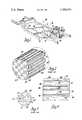
- FIG. 2is a sectional pictorial view showing the construction of a conventional monolithic ceramic filter used in the particulate traps in the structure of FIG. 1;
- FIG. 3is a pictorial view of a portion of the inlet face of the filter of FIG. 2;
- FIG. 4is a pictorial sectional view of a portion of a filter of the type shown in FIGS. 2 and 3 but with the inlet channel thereof a configuration and which is formed in accordance with the subject invention.
- FIG. 1generally indicates a vehicle chassis, portions of which have been omitted from the drawing for clarity.
- the chassis 10includes a vehicle frame 11 on which is mounted a V-type diesel engine 12.
- Engine 12includes a pair of cylinder banks each mounting an exhaust manifold 14 connected in an engine exhaust system, the right hand manifold being the only one visible in the figure.
- Each exhaust manifoldconnects through a suitable exhaust pipe 15 with an exhaust emission control system which includes an exhaust particulate trap 16 suitably supported in the vehicle frame by means not shown and adapted to collect particulates in the exhaust gases delivered to the traps from the cylinders of the respective cylinder banks.
- the outlets of the traps 16are connected through a wye pipe 18 with a muffler 19, which in turn connects through a tailpipe 20 with the rear of the vehicle for passing the exhaust gases to atmosphere.
- Each of the particulate traps 16includes a housing which may be of any form of construction and configuration suitable for the purpose.
- an incineration cleanable ceramic filter elementwhich may be of the type disclosed in the above-identified U.S. Pat. No. 4,276,071 and which may have any of a number of possible configurations such as, for example, that of the element illustrated in FIG. 2 and generally indicated by numeral 22.
- the emission control systemalso includes suitable heater means, such as electrical heater means or fuel burner means, not shown, to supply necessary heat to effect incineration of particulates previously trapped by the filters to effect regeneration thereof.
- Filter element 22 shown in FIG. 2is in the form of a ceramic monolith having a surrounding cylindrical outer wall 23 internally interconnected by a large number of interlaced thin porous internal walls 24.
- the interlaced wallsdefine internally thereof two groups of parallel passages or channels including respectively inlet channels 26 and outlet channels 27, each extending to opposite ends of the element 22.
- the inlet channels 26are open at the inlet end 28 of the element and are closed at the outlet end 30 of the element, while the outlet channels 27 are closed at the element inlet end 28 and open at the outlet end 30.
- the channelsare of square cross-section as best seen in FIG. 3, although, as disclosed in the above-identified U.S. Pat. No. 4,276,071, numerous other configurations could be utilized.
- the inlet and outlet channelsare arranged in vertical and horizontal rows (as viewed in cross-section), as shown in FIG. 3, with the inlet channels 26 alternating with exhaust channels 27 in a checkerboard pattern.
- each interior wall portion of the elementlies between an inlet channel and an outlet channel at every point of its surface except where it engages another wall, as it does at the corners of the channels. So, except for the corner engagement, the inlet channels 26 are spaced from one another by intervening outlet channels 27 and vice versa.
- the construction of the ceramic monolithis such that the interior walls 24 are porous so as to permit passage of exhaust gases through the walls from the inlet to the outlet channels.
- the porosity of the wallsis sized appropriately to filter out a substantial portion of the particulates present in diesel exhaust gases.
- testshave indicated that efficient filtration is provided by a ceramic wall structure having an average porosity of about 10 percent, a mean pore size of from about 2 to 15 microns in a range or pore sizes of from about 0.5 microns to about 70 microns. This has been accomplished in a monolith structure having square passages measuring on the average about 0.06 inches on a side with a wall thickness of about 0.015 inches between passages.
- the axial distribution of particulates along a given inlet channel 26is controlled by the gas flow within the monolith filter.
- a constant-area triangular sector of an inlet channel 26communicates with an identical sector of an adjacent outlet channel 27, the flow through only one wall 24 being illustrated in this Figure.
- the gas flow through this type known filter structureis thus completely defined by the solution for parallel-flow through a uniformly-porous wall with constant-area inlet and outlet channels as described, for example, in the publication by A. L. London, G. Klopfer and S.
- Xis the distance from the inlet face of an inlet channel
- Lis the total length of an inlet channel.
- a monolith filterin accordance with the invention, is provided with inlet channels each having decreasing flow-area with X/L, constant-area outlet channels and, with the porous walls therebetween of increasing wall thickness with X/L, the increasing thickness being effected on the inlet channel side of the porous walls.
- a carrier fluidsuch as clean water
- the ceramic powder 40 carried by the carrier fluidwill be filtered out from the carrier fluid by the porous walls and this ceramic powder will accumulate along the inlet channel walls according to the axial distribution of transverse velocity.
- This deposition of ceramic powder 40will be effective to both increase the wall thickness and to decrease the inlet channel area with increasing X/L.
- the ceramic powder 40is schematically shown on two opposed wall 24 sides only in the inlet channels 26 in FIG. 4.
- the ceramic powder 40 as deposited by being trapped on the inlet channel surface of the porous walls 24changes the configuration of the walls so that each of the wall surfaces defining an inlet channel is inclined toward the nominal axis of the channel, that is, inclined upward from the inlet end 28 to the outlet end 30 toward this axis.
- the monolith filter with the ceramic powder deposited on the walls of the inlet channelsis removed from the stream and then it is fired to fix the ceramic powder to the inlet channel walls.
- the ceramic powder as thus trapped by the porous walls and then fired in placebecome, in effect, an integral part of such porous walls 24.
- FIG. 4shows the approximate effect of this deposition process of ceramic powder on inlet channel area and wall thickness for a particular embodiment.
- the unit 1represents a given cross-sectional area at the inlet end of the inlet channel with the actual cross-sectional area ideally decreasing by the fraction units shown as the fraction of the total distance from the inlet end increases.
- the reduction in the inlet channel areais less than the ideal shown in the second column, but this variation between actual and ideal cross-sectional areas is compensated for by an actual increase in wall thickness so that the resulting inlet channel configuration and wall thickness will provide for a relatively uniform axial particulate trapping distribution when the filter of the invention is used on a diesel engine emission control system.
- a ceramic wall-flow monolith filter 22such as shown in FIG. 2 would be supported in a suitable housing similar to that of the particulate traps 16 shown in FIG. 1, with the stream of the ceramic powder and carrier fluid supplied to it by a suitable supply conduit, not shown, which may be a conduit similar to the exhaust pipe 15 suitably connected to a trap.
- the outlet of the trap housingwould be connected by a similar conduit to a suitable reservois, not shown, for containing the carrier fluid at atmospheric pressure, via, preferably, a conventional, commercially available filter system, not shown, of the type suitable for removing any small dust particles that may remain in the carrier fluid after its passage through the filter.
- the amount of ceramic powder 40 which is added to a particular monolith filter 22 in order to substantially homogenize the flow through the walls 24 to obtain substantially uniform particulate trappingcan be predetermined, for example, experimentally by fabricating and testing the particulate filters with different quantities of ceramic powder added in the manner described hereinabove. After the required amount of ceramic powder 40 for a particular basic filter structure has been determined, the ceramic powder 40 addition can be controlled either by adding this quantity of ceramic powder to a carrier fluid and flowing this stream until all of the powder has been added and delivered to the monolith filter or by controlling the time during which a uniform aqueous ceramic powder dispersion is flowed through the monolith filter.
- the ceramic powder 40is preferably composed of the same material as that used in the fabrication of the monolithic structure of the filter 22 and is preferably of the type disclosed in U.S. Pat. No. 3,954,672 entitled Cordierite Refractory Compositions and Method of Forming Same issued May 4, 1976 to Arthur V. Somers, Morris Berg and Archie A. Shukle, the disclosure of which is incorporated herein by reference thereto. Accordingly, the ceramic powder can be fired in the same manner as disclosed in this patent.
Landscapes
- Chemical & Material Sciences (AREA)
- Physics & Mathematics (AREA)
- Geometry (AREA)
- Engineering & Computer Science (AREA)
- Chemical Kinetics & Catalysis (AREA)
- Ceramic Engineering (AREA)
- Inorganic Chemistry (AREA)
- Life Sciences & Earth Sciences (AREA)
- Geology (AREA)
- Materials Engineering (AREA)
- Structural Engineering (AREA)
- Organic Chemistry (AREA)
- Combustion & Propulsion (AREA)
- Mechanical Engineering (AREA)
- General Engineering & Computer Science (AREA)
- Filtering Materials (AREA)
- Processes For Solid Components From Exhaust (AREA)
- Filtering Of Dispersed Particles In Gases (AREA)
Abstract
Description
TABLE ______________________________________ Approximate Inlet Channel Modifications Achievable with Deposition All Quantities Normalized on the Value at Entrance to Inlet Channel After Deposition and Firing of Ceramic Powder "Ideal" Incremental Transverse Area for Uniform Wall Channel X/L Velocity Transverse Velocity Thickness Area ______________________________________ 0 1.00 1.00 0.39 1.00 1/4 1.33 0.74 0.52 0.79 1/2 1.58 0.47 0.61 0.63 3/4 2.00 0.22 0.78 0.37 1 2.58 0 1.00 0 ______________________________________
Claims (2)
Priority Applications (2)
| Application Number | Priority Date | Filing Date | Title |
|---|---|---|---|
| US06/345,005US4390355A (en) | 1982-02-02 | 1982-02-02 | Wall-flow monolith filter |
| US06/455,926US4423090A (en) | 1982-02-02 | 1983-01-06 | Method of making wall-flow monolith filter |
Applications Claiming Priority (1)
| Application Number | Priority Date | Filing Date | Title |
|---|---|---|---|
| US06/345,005US4390355A (en) | 1982-02-02 | 1982-02-02 | Wall-flow monolith filter |
Related Child Applications (1)
| Application Number | Title | Priority Date | Filing Date |
|---|---|---|---|
| US06/455,926DivisionUS4423090A (en) | 1982-02-02 | 1983-01-06 | Method of making wall-flow monolith filter |
Publications (1)
| Publication Number | Publication Date |
|---|---|
| US4390355Atrue US4390355A (en) | 1983-06-28 |
Family
ID=23353069
Family Applications (1)
| Application Number | Title | Priority Date | Filing Date |
|---|---|---|---|
| US06/345,005Expired - LifetimeUS4390355A (en) | 1982-02-02 | 1982-02-02 | Wall-flow monolith filter |
Country Status (1)
| Country | Link |
|---|---|
| US (1) | US4390355A (en) |
Cited By (57)
| Publication number | Priority date | Publication date | Assignee | Title |
|---|---|---|---|---|
| US4512786A (en)* | 1982-04-21 | 1985-04-23 | Mazda Motor Corporation | Exhaust gas purifying device |
| WO1985002785A1 (en)* | 1983-12-27 | 1985-07-04 | Ford Motor Company Limited | Regenerative filter trap system with apparatus for diverting the exhaust gas flow |
| US4652286A (en)* | 1982-02-16 | 1987-03-24 | Matsushita Electric Industrial Co., Ltd. | Exhaust gas filter |
| EP0234218A1 (en)* | 1986-02-19 | 1987-09-02 | FEV Forschungsgesellschaft für Energietechnik und Verbrennungsmotoren mbH | Regeneration system for exhaust gas particle filter systems |
| US4695301A (en)* | 1985-02-11 | 1987-09-22 | Nippondenso Co., Ltd. | Porous ceramic monoliths |
| US4718926A (en)* | 1985-03-08 | 1988-01-12 | Matsushita Electric Industrial Co., Ltd. | Exhaust gas filter for diesel engine |
| US4732593A (en)* | 1985-06-24 | 1988-03-22 | Nippondenso Co., Ltd. | Sintered ceramic filter structure having body compressively stressed by sintered ceramic material having different sintering shrinkage ratio |
| US4759918A (en)* | 1987-04-16 | 1988-07-26 | Allied-Signal Inc. | Process for the reduction of the ignition temperature of diesel soot |
| EP0277012A1 (en)* | 1987-01-28 | 1988-08-03 | Ngk Insulators, Ltd. | Ceramic honeycomb filter for purifying exhaust gases |
| EP0330161A3 (en)* | 1988-02-26 | 1990-09-26 | Daimler-Benz Aktiengesellschaft | Method for the fabrication of a filter for soot particles |
| US4976760A (en)* | 1987-12-02 | 1990-12-11 | Cercona, Inc. | Porous ceramic article for use as a filter for removing particulates from diesel exhaust gases |
| US5089237A (en)* | 1989-07-20 | 1992-02-18 | Daimler-Benz Ag | Gas filter with catalytic coating and a gastight downstream region |
| US5126047A (en)* | 1990-05-07 | 1992-06-30 | The Carborundum Company | Molten metal filter |
| EP0570384A4 (en)* | 1991-01-10 | 1993-12-22 | Ceramem Corporation | Back flushable filtration device and method of forming and using same |
| US5318755A (en)* | 1992-11-30 | 1994-06-07 | A. Ahlstrom Corporation | Method and apparatus for cleaning flue gases |
| US5492679A (en)* | 1993-03-08 | 1996-02-20 | General Motors Corporation | Zeolite/catalyst wall-flow monolith adsorber |
| US5641332A (en)* | 1995-12-20 | 1997-06-24 | Corning Incorporated | Filtraion device with variable thickness walls |
| US5655366A (en)* | 1994-05-17 | 1997-08-12 | Isuzu Ceramics Research Institute Co. Ltd. | Diesel particulate filter |
| US5833932A (en)* | 1993-03-26 | 1998-11-10 | Siemens Aktiengesellschaft | Catalytic converter for nitrogen oxide reduction in the exhaust gas of an internal combustion engine |
| US5865864A (en)* | 1995-02-20 | 1999-02-02 | Emitec Gesellschaft Fuer Emissionstechnologie Mbh | Honeycomb body having channels of different flow resistance through which a fluid can flow and apparatus having the honeycomb body for cleaning exhaust gas |
| US5997744A (en)* | 1997-12-16 | 1999-12-07 | Limaye; Santosh Y. | Fluid separation module having a porous monolithic core |
| US6024927A (en)* | 1993-01-06 | 2000-02-15 | Sumitomo Electric Industries, Ltd. | Particulate trap |
| EP1074291A1 (en)* | 1999-08-04 | 2001-02-07 | Technologies Avancees & Membranes Industrielles S.A. | Cross-flow filtration membrane and method for manufacturing the same |
| US6375014B1 (en)* | 1997-04-09 | 2002-04-23 | Societe Des Ceramiques Techniques | Graded permeability macroporous support for crossflow filtration |
| WO2002032545A1 (en)* | 2000-10-13 | 2002-04-25 | Corning Incorporated | Honeycomb particulate filters |
| US20030086837A1 (en)* | 2000-05-30 | 2003-05-08 | Rolf Bruck | Particle trap and assemblies and exhaust tracts having the particle trap |
| WO2003072915A1 (en)* | 2002-02-28 | 2003-09-04 | Csir | Treatment of exhaust gases from an internal combustion engine |
| US20030165638A1 (en)* | 2001-07-06 | 2003-09-04 | Louks John W. | Inorganic fiber substrates for exhaust systems and methods of making same |
| US20030167757A1 (en)* | 2002-01-25 | 2003-09-11 | Gianmarco Boretto | Method of determining the amount of particulate accumulated in a particulate filter |
| WO2004036003A1 (en)* | 2002-10-15 | 2004-04-29 | Robert Bosch Gmbh | Exhaust gas post treatment arrangement |
| US20040132607A1 (en)* | 2003-01-08 | 2004-07-08 | 3M Innovative Properties Company | Ceramic fiber composite and method for making the same |
| US6764532B1 (en) | 2003-03-03 | 2004-07-20 | General Motors Corporation | Method and apparatus for filtering exhaust particulates |
| US20040231307A1 (en)* | 2001-07-06 | 2004-11-25 | Wood Thomas E. | Inorganic fiber substrates for exhaust systems and methods of making same |
| US20050050870A1 (en)* | 2003-03-03 | 2005-03-10 | Cheng Shi-Wai S. | Method and apparatus for filtering exhaust particulates |
| US20050235622A1 (en)* | 2004-04-23 | 2005-10-27 | Cutler Willard A | Diesel engine exhaust filters |
| US20060059899A1 (en)* | 2002-04-12 | 2006-03-23 | Illinois Valley Holding Company | Apparatus and method for filtering particulate and NOx emissions |
| US20070022724A1 (en)* | 2005-07-29 | 2007-02-01 | Gargano Patrick M | Method, system and apparatus for detecting defects in a honeycomb body using a particulate fluid |
| US20070113831A1 (en)* | 2005-11-18 | 2007-05-24 | Hoke Jeffrey B | Hydrocarbon adsorpotion method and device for controlling evaporative emissions from the fuel storage system of motor vehicles |
| US20070119135A1 (en)* | 2005-11-30 | 2007-05-31 | Weiguo Miao | Controlled pore size distribution porous ceramic honeycomb filter, honeycomb green body, batch mixture and manufacturing method therefor |
| US20070238256A1 (en)* | 2006-03-31 | 2007-10-11 | Michael Fischer | Catalytic flow-through fast light off ceramic substrate and method of manufacture |
| US20070292707A1 (en)* | 2005-02-18 | 2007-12-20 | Emitec Gesellschaft Fur Emissiontechnologie Mbh | Honeycomb Body With Internal Cavities |
| US20080110143A1 (en)* | 2006-11-15 | 2008-05-15 | Peng Chen | Filters with controlled submicron porosity |
| US20080314008A1 (en)* | 2005-10-05 | 2008-12-25 | Robert Bosch Gmbh | Filter Element and Filter for Exhaust-Gas Aftertreatment |
| US20090087613A1 (en)* | 2007-08-31 | 2009-04-02 | Yanxia Lu | Cordierite honeycomb article and method of manufacture |
| US20100115930A1 (en)* | 2008-11-07 | 2010-05-13 | Gm Global Technology Operations, Inc. | Exhaust after treatment system |
| US20100180772A1 (en)* | 2009-01-21 | 2010-07-22 | Douglas Munroe Beall | Particulate Filters and Methods for Regenerating Particulate Filters |
| US20100180561A1 (en)* | 2009-01-21 | 2010-07-22 | Douglas Munroe Beall | Filtration Structures For Improved Particulate Filter Performance |
| US20100234206A1 (en)* | 2006-11-30 | 2010-09-16 | Weiguo Miao | Controlled Pore Size Distribution Porous Ceramic Honeycomb Filter, Honeycomb Green Body, Batch Mixture And Manufacturing Method Therefor |
| US20100247400A1 (en)* | 2009-03-31 | 2010-09-30 | Ngk Insulators, Ltd. | Honeycomb filter and method of manufacturing the same |
| US20100269488A1 (en)* | 2003-08-01 | 2010-10-28 | Bailey John M | Particulate trap system and method |
| US20110113761A1 (en)* | 2009-11-13 | 2011-05-19 | Basf Corporation | Wall Flow Filter Loaded With SCR Catalyst, Systems and Methods of Exhaust Gas Treatment |
| EP2339135A1 (en)* | 2009-12-25 | 2011-06-29 | NGK Insulators, Ltd. | Substrate with surface-collection-layer and catalyst-carrying substrate with surface-collection-layer |
| US8591623B2 (en) | 2008-02-29 | 2013-11-26 | Corning Incorporated | Honeycomb manufacturing method using ground nut shells and honeycomb body produced thereby |
| US20170246593A1 (en)* | 2014-08-11 | 2017-08-31 | Technologies Avancees Et Membranes Industrielles | Novel shapes for tangential flow separation single-channel tubular elements incorporating turbulence promoters, and method of fabrication |
| EP3574983A3 (en)* | 2015-06-28 | 2020-02-26 | Johnson Matthey Public Limited Company | Catalytic wall-flow filter having a membrane |
| WO2020254208A1 (en) | 2019-06-21 | 2020-12-24 | Climeworks Ag | Adsorber structure for gas separation processes |
| WO2025031905A1 (en) | 2023-08-07 | 2025-02-13 | Climeworks Ag | Modular adsorber structure for gas separation processes |
Citations (5)
| Publication number | Priority date | Publication date | Assignee | Title |
|---|---|---|---|---|
| US4072007A (en)* | 1976-03-03 | 1978-02-07 | Westinghouse Electric Corporation | Gas turbine combustor employing plural catalytic stages |
| US4251239A (en)* | 1978-08-28 | 1981-02-17 | Clyde Robert A | Multi-purpose ceramic element |
| US4276071A (en)* | 1979-12-03 | 1981-06-30 | General Motors Corporation | Ceramic filters for diesel exhaust particulates |
| US4283207A (en)* | 1980-06-19 | 1981-08-11 | General Motors Corporation | Diesel exhaust filter-incinerator |
| US4329162A (en)* | 1980-07-03 | 1982-05-11 | Corning Glass Works | Diesel particulate trap |
- 1982
- 1982-02-02USUS06/345,005patent/US4390355A/ennot_activeExpired - Lifetime
Patent Citations (5)
| Publication number | Priority date | Publication date | Assignee | Title |
|---|---|---|---|---|
| US4072007A (en)* | 1976-03-03 | 1978-02-07 | Westinghouse Electric Corporation | Gas turbine combustor employing plural catalytic stages |
| US4251239A (en)* | 1978-08-28 | 1981-02-17 | Clyde Robert A | Multi-purpose ceramic element |
| US4276071A (en)* | 1979-12-03 | 1981-06-30 | General Motors Corporation | Ceramic filters for diesel exhaust particulates |
| US4283207A (en)* | 1980-06-19 | 1981-08-11 | General Motors Corporation | Diesel exhaust filter-incinerator |
| US4329162A (en)* | 1980-07-03 | 1982-05-11 | Corning Glass Works | Diesel particulate trap |
Non-Patent Citations (1)
| Title |
|---|
| London, A. L., et al., Oblique Flow Headers for Heat Exchangers-The Ideal Geometries and the Evacuation of Losses, Technical Report No. 63, Aug. 1966.* |
Cited By (93)
| Publication number | Priority date | Publication date | Assignee | Title |
|---|---|---|---|---|
| US4652286A (en)* | 1982-02-16 | 1987-03-24 | Matsushita Electric Industrial Co., Ltd. | Exhaust gas filter |
| US4512786A (en)* | 1982-04-21 | 1985-04-23 | Mazda Motor Corporation | Exhaust gas purifying device |
| WO1985002785A1 (en)* | 1983-12-27 | 1985-07-04 | Ford Motor Company Limited | Regenerative filter trap system with apparatus for diverting the exhaust gas flow |
| US4695301A (en)* | 1985-02-11 | 1987-09-22 | Nippondenso Co., Ltd. | Porous ceramic monoliths |
| US4718926A (en)* | 1985-03-08 | 1988-01-12 | Matsushita Electric Industrial Co., Ltd. | Exhaust gas filter for diesel engine |
| US4732593A (en)* | 1985-06-24 | 1988-03-22 | Nippondenso Co., Ltd. | Sintered ceramic filter structure having body compressively stressed by sintered ceramic material having different sintering shrinkage ratio |
| EP0234218A1 (en)* | 1986-02-19 | 1987-09-02 | FEV Forschungsgesellschaft für Energietechnik und Verbrennungsmotoren mbH | Regeneration system for exhaust gas particle filter systems |
| EP0277012A1 (en)* | 1987-01-28 | 1988-08-03 | Ngk Insulators, Ltd. | Ceramic honeycomb filter for purifying exhaust gases |
| US4857089A (en)* | 1987-01-28 | 1989-08-15 | Ngk Insulators, Ltd. | Ceramic honeycomb filter for purifying exhaust gases |
| US4759918A (en)* | 1987-04-16 | 1988-07-26 | Allied-Signal Inc. | Process for the reduction of the ignition temperature of diesel soot |
| US4976760A (en)* | 1987-12-02 | 1990-12-11 | Cercona, Inc. | Porous ceramic article for use as a filter for removing particulates from diesel exhaust gases |
| EP0330161A3 (en)* | 1988-02-26 | 1990-09-26 | Daimler-Benz Aktiengesellschaft | Method for the fabrication of a filter for soot particles |
| US5089237A (en)* | 1989-07-20 | 1992-02-18 | Daimler-Benz Ag | Gas filter with catalytic coating and a gastight downstream region |
| US5126047A (en)* | 1990-05-07 | 1992-06-30 | The Carborundum Company | Molten metal filter |
| EP0570384A4 (en)* | 1991-01-10 | 1993-12-22 | Ceramem Corporation | Back flushable filtration device and method of forming and using same |
| US5318755A (en)* | 1992-11-30 | 1994-06-07 | A. Ahlstrom Corporation | Method and apparatus for cleaning flue gases |
| US6024927A (en)* | 1993-01-06 | 2000-02-15 | Sumitomo Electric Industries, Ltd. | Particulate trap |
| US5492679A (en)* | 1993-03-08 | 1996-02-20 | General Motors Corporation | Zeolite/catalyst wall-flow monolith adsorber |
| US5833932A (en)* | 1993-03-26 | 1998-11-10 | Siemens Aktiengesellschaft | Catalytic converter for nitrogen oxide reduction in the exhaust gas of an internal combustion engine |
| US5655366A (en)* | 1994-05-17 | 1997-08-12 | Isuzu Ceramics Research Institute Co. Ltd. | Diesel particulate filter |
| US5865864A (en)* | 1995-02-20 | 1999-02-02 | Emitec Gesellschaft Fuer Emissionstechnologie Mbh | Honeycomb body having channels of different flow resistance through which a fluid can flow and apparatus having the honeycomb body for cleaning exhaust gas |
| US5641332A (en)* | 1995-12-20 | 1997-06-24 | Corning Incorporated | Filtraion device with variable thickness walls |
| US6375014B1 (en)* | 1997-04-09 | 2002-04-23 | Societe Des Ceramiques Techniques | Graded permeability macroporous support for crossflow filtration |
| US5997744A (en)* | 1997-12-16 | 1999-12-07 | Limaye; Santosh Y. | Fluid separation module having a porous monolithic core |
| FR2797198A1 (en)* | 1999-08-04 | 2001-02-09 | Tami Ind | MEMBRANE FOR TANGENTIAL FILTRATION AND ITS MANUFACTURING METHOD |
| EP1074291A1 (en)* | 1999-08-04 | 2001-02-07 | Technologies Avancees & Membranes Industrielles S.A. | Cross-flow filtration membrane and method for manufacturing the same |
| US6499606B1 (en) | 1999-08-04 | 2002-12-31 | Technologies Avancees & Membranes Industrielles (Societe Anonyme) | Cross-flow filter membrane and method of manufacturing it |
| US20030070981A1 (en)* | 1999-08-04 | 2003-04-17 | Technologies Avancees & Membranes Industrielles (Societe Anonyme) | Cross-flow filter membrane and method of manufacturing it |
| US6780466B2 (en)* | 1999-08-04 | 2004-08-24 | Technologies Avancees & Membranes Industrielles | Cross-flow filter membrane and method of manufacturing it |
| US20030086837A1 (en)* | 2000-05-30 | 2003-05-08 | Rolf Bruck | Particle trap and assemblies and exhaust tracts having the particle trap |
| US7267805B2 (en)* | 2000-05-30 | 2007-09-11 | Emitec Gesellschaft Fuer Emissionstechnologie Mbh | Particle trap and assemblies and exhaust tracts having the particle trap |
| WO2002032545A1 (en)* | 2000-10-13 | 2002-04-25 | Corning Incorporated | Honeycomb particulate filters |
| US6508852B1 (en)* | 2000-10-13 | 2003-01-21 | Corning Incorporated | Honeycomb particulate filters |
| US20040231307A1 (en)* | 2001-07-06 | 2004-11-25 | Wood Thomas E. | Inorganic fiber substrates for exhaust systems and methods of making same |
| US7404840B2 (en) | 2001-07-06 | 2008-07-29 | 3M Innovative Properties Company | Chemically stabilized β-cristobalite and ceramic bodies comprising same |
| US20030165638A1 (en)* | 2001-07-06 | 2003-09-04 | Louks John W. | Inorganic fiber substrates for exhaust systems and methods of making same |
| US20030167757A1 (en)* | 2002-01-25 | 2003-09-11 | Gianmarco Boretto | Method of determining the amount of particulate accumulated in a particulate filter |
| US6941750B2 (en)* | 2002-01-25 | 2005-09-13 | C.R.F Societa Consortile Per Azioni | Method of determining the amount of particulate accumulated in a particulate filter |
| US20050232829A1 (en)* | 2002-02-28 | 2005-10-20 | Fuls Paul F | Treatment of exhaust gases from an internal combustion engine |
| WO2003072915A1 (en)* | 2002-02-28 | 2003-09-04 | Csir | Treatment of exhaust gases from an internal combustion engine |
| US7273514B2 (en) | 2002-04-12 | 2007-09-25 | Illinois Valley Holding Company | Apparatus and method for filtering particulate and NOx emissions |
| US20060059899A1 (en)* | 2002-04-12 | 2006-03-23 | Illinois Valley Holding Company | Apparatus and method for filtering particulate and NOx emissions |
| WO2004036003A1 (en)* | 2002-10-15 | 2004-04-29 | Robert Bosch Gmbh | Exhaust gas post treatment arrangement |
| US20060008396A1 (en)* | 2002-10-15 | 2006-01-12 | Stephan Wursthorn | Exhaust gas post treatment arrangement |
| US20040132607A1 (en)* | 2003-01-08 | 2004-07-08 | 3M Innovative Properties Company | Ceramic fiber composite and method for making the same |
| US7201572B2 (en) | 2003-01-08 | 2007-04-10 | 3M Innovative Properties Company | Ceramic fiber composite and method for making the same |
| US20060156702A1 (en)* | 2003-03-03 | 2006-07-20 | Cheng Shi-Wai S | Method and apparatus for filtering exhaust particulates |
| US7524360B2 (en) | 2003-03-03 | 2009-04-28 | Gm Global Technology Operations, Inc. | Method and apparatus for filtering exhaust particulates |
| US20050050870A1 (en)* | 2003-03-03 | 2005-03-10 | Cheng Shi-Wai S. | Method and apparatus for filtering exhaust particulates |
| US6764532B1 (en) | 2003-03-03 | 2004-07-20 | General Motors Corporation | Method and apparatus for filtering exhaust particulates |
| US20100269488A1 (en)* | 2003-08-01 | 2010-10-28 | Bailey John M | Particulate trap system and method |
| US7992382B2 (en) | 2003-08-01 | 2011-08-09 | Illinois Valley Holding Company | Particulate trap system and method |
| US7238217B2 (en) | 2004-04-23 | 2007-07-03 | Corning Incorporated | Diesel engine exhaust filters |
| US20050235622A1 (en)* | 2004-04-23 | 2005-10-27 | Cutler Willard A | Diesel engine exhaust filters |
| US7981498B2 (en)* | 2005-02-18 | 2011-07-19 | Emitec Gesellschaft Fuer Emissionstechnologies Mbh | Honeycomb body with internal cavities |
| US20070292707A1 (en)* | 2005-02-18 | 2007-12-20 | Emitec Gesellschaft Fur Emissiontechnologie Mbh | Honeycomb Body With Internal Cavities |
| US20070022724A1 (en)* | 2005-07-29 | 2007-02-01 | Gargano Patrick M | Method, system and apparatus for detecting defects in a honeycomb body using a particulate fluid |
| US7648549B2 (en)* | 2005-07-29 | 2010-01-19 | Corning Incorporated | Method, system and apparatus for detecting defects in a honeycomb body using a particulate fluid |
| US20080314008A1 (en)* | 2005-10-05 | 2008-12-25 | Robert Bosch Gmbh | Filter Element and Filter for Exhaust-Gas Aftertreatment |
| US7753034B2 (en) | 2005-11-18 | 2010-07-13 | Basf Corporation, | Hydrocarbon adsorption method and device for controlling evaporative emissions from the fuel storage system of motor vehicles |
| EP2063098A1 (en) | 2005-11-18 | 2009-05-27 | Basf Catalysts Llc | Hydrocarbon adsorption method and device for controlling evaporative emissions from the fuel storage system of motor vehicles |
| US20070113831A1 (en)* | 2005-11-18 | 2007-05-24 | Hoke Jeffrey B | Hydrocarbon adsorpotion method and device for controlling evaporative emissions from the fuel storage system of motor vehicles |
| US20070119135A1 (en)* | 2005-11-30 | 2007-05-31 | Weiguo Miao | Controlled pore size distribution porous ceramic honeycomb filter, honeycomb green body, batch mixture and manufacturing method therefor |
| US7744670B2 (en) | 2005-11-30 | 2010-06-29 | Corning Incorporated | Controlled pore size distribution porous ceramic honeycomb filter, honeycomb green body, batch mixture and manufacturing method therefor |
| US7722827B2 (en)* | 2006-03-31 | 2010-05-25 | Corning Incorporated | Catalytic flow-through fast light off ceramic substrate and method of manufacture |
| US20070238256A1 (en)* | 2006-03-31 | 2007-10-11 | Michael Fischer | Catalytic flow-through fast light off ceramic substrate and method of manufacture |
| US20080110143A1 (en)* | 2006-11-15 | 2008-05-15 | Peng Chen | Filters with controlled submicron porosity |
| US8298311B2 (en) | 2006-11-15 | 2012-10-30 | Corning Incorporated | Filters with controlled submicron porosity |
| US20100234206A1 (en)* | 2006-11-30 | 2010-09-16 | Weiguo Miao | Controlled Pore Size Distribution Porous Ceramic Honeycomb Filter, Honeycomb Green Body, Batch Mixture And Manufacturing Method Therefor |
| US7981188B2 (en) | 2006-11-30 | 2011-07-19 | Corning Incorporated | Controlled pore size distribution porous ceramic honeycomb filter, honeycomb green body, batch mixture and manufacturing method therefor |
| US7887897B2 (en) | 2007-08-31 | 2011-02-15 | Corning Incorporated | Cordierite honeycomb article and method of manufacture |
| US20090087613A1 (en)* | 2007-08-31 | 2009-04-02 | Yanxia Lu | Cordierite honeycomb article and method of manufacture |
| US8591623B2 (en) | 2008-02-29 | 2013-11-26 | Corning Incorporated | Honeycomb manufacturing method using ground nut shells and honeycomb body produced thereby |
| US20100115930A1 (en)* | 2008-11-07 | 2010-05-13 | Gm Global Technology Operations, Inc. | Exhaust after treatment system |
| US8231701B2 (en) | 2009-01-21 | 2012-07-31 | Corning Incorporated | Particulate filters and methods for regenerating particulate filters |
| US20100180772A1 (en)* | 2009-01-21 | 2010-07-22 | Douglas Munroe Beall | Particulate Filters and Methods for Regenerating Particulate Filters |
| US20100180561A1 (en)* | 2009-01-21 | 2010-07-22 | Douglas Munroe Beall | Filtration Structures For Improved Particulate Filter Performance |
| US8187353B2 (en) | 2009-01-21 | 2012-05-29 | Corning Incorporated | Filtration structures for improved particulate filter performance |
| JP2010234317A (en)* | 2009-03-31 | 2010-10-21 | Ngk Insulators Ltd | Honeycomb filter |
| US20100247400A1 (en)* | 2009-03-31 | 2010-09-30 | Ngk Insulators, Ltd. | Honeycomb filter and method of manufacturing the same |
| US8343431B2 (en)* | 2009-03-31 | 2013-01-01 | Ngk Insulators, Ltd. | Honeycomb filter and method of manufacturing the same |
| US9657625B2 (en)* | 2009-11-13 | 2017-05-23 | Basf Corporation | Wall flow filter loaded with SCR catalyst, systems and methods of exhaust gas treatment |
| US20110113761A1 (en)* | 2009-11-13 | 2011-05-19 | Basf Corporation | Wall Flow Filter Loaded With SCR Catalyst, Systems and Methods of Exhaust Gas Treatment |
| US9175587B2 (en) | 2009-12-25 | 2015-11-03 | Ngk Insulators, Ltd. | Substrate with surface-collection-layer and catalyst-carrying substrate with surface-collection-layer |
| US20110212831A1 (en)* | 2009-12-25 | 2011-09-01 | Ngk Insulators, Ltd. | Substrate with surface-collection-layer and catalyst-carrying substrate with surface-collection-layer |
| EP2339135A1 (en)* | 2009-12-25 | 2011-06-29 | NGK Insulators, Ltd. | Substrate with surface-collection-layer and catalyst-carrying substrate with surface-collection-layer |
| US20170246593A1 (en)* | 2014-08-11 | 2017-08-31 | Technologies Avancees Et Membranes Industrielles | Novel shapes for tangential flow separation single-channel tubular elements incorporating turbulence promoters, and method of fabrication |
| US10478781B2 (en)* | 2014-08-11 | 2019-11-19 | Technologies Avancees Et Membranes Industrielles | Shapes for tangential flow separation single-channel tubular elements incorporating turbulence promoters, and method of fabrication |
| EP3574983A3 (en)* | 2015-06-28 | 2020-02-26 | Johnson Matthey Public Limited Company | Catalytic wall-flow filter having a membrane |
| WO2020254208A1 (en) | 2019-06-21 | 2020-12-24 | Climeworks Ag | Adsorber structure for gas separation processes |
| US20220193598A1 (en)* | 2019-06-21 | 2022-06-23 | Climeworks Ag | Adsorber structure for gas separation processes |
| US12268983B2 (en)* | 2019-06-21 | 2025-04-08 | Climeworks Ag | Adsorber structure for gas separation processes |
| WO2025031905A1 (en) | 2023-08-07 | 2025-02-13 | Climeworks Ag | Modular adsorber structure for gas separation processes |
Similar Documents
| Publication | Publication Date | Title |
|---|---|---|
| US4390355A (en) | Wall-flow monolith filter | |
| US4423090A (en) | Method of making wall-flow monolith filter | |
| US4420316A (en) | Filter apparatus and method of making it | |
| EP0089756B1 (en) | Particulate filters for use with diesel engines | |
| US4417908A (en) | Honeycomb filter and method of making it | |
| US4833883A (en) | Filter unit, and apparatus for treating particulates in an exhaust gas from a diesel engine | |
| US4875335A (en) | Apparatus and method for treating an exhaust gas from a diesel engine | |
| EP1450015B1 (en) | Honeycomb filter and exhaust gas purification system | |
| US4329162A (en) | Diesel particulate trap | |
| US4276071A (en) | Ceramic filters for diesel exhaust particulates | |
| US5592925A (en) | Exhaust gas recirculation device for internal combustion engine | |
| US6024927A (en) | Particulate trap | |
| US6800107B2 (en) | Exhaust gas purifying filter | |
| EP0090492B1 (en) | Solid particulate filtering apparatus | |
| JPH0550323B2 (en) | ||
| WO2003011427A1 (en) | Honeycomb structural body and method of manufacturing the structural body | |
| WO2008086447A1 (en) | Pleated diesel particulate filter assembly | |
| US4667469A (en) | Exhaust gas filter for diesel engines | |
| US7524360B2 (en) | Method and apparatus for filtering exhaust particulates | |
| US8092565B2 (en) | Particulate filter | |
| JPS62225221A (en) | Particulates trap | |
| KR101014399B1 (en) | Ceramic filter | |
| EP2234692A1 (en) | Particulate filtration device | |
| JP2587068B2 (en) | Apparatus for treating particulates in diesel engine exhaust gas | |
| JP2590943Y2 (en) | Exhaust gas purification device |
Legal Events
| Date | Code | Title | Description |
|---|---|---|---|
| AS | Assignment | Owner name:GENERAL MOTORS CORPORATION, DETROIT, MI. A CORP. Free format text:ASSIGNMENT OF ASSIGNORS INTEREST.;ASSIGNORS:HAMMOND, DEAN C. JR;VICKERS, PAUL T.;REEL/FRAME:003960/0654 Effective date:19820120 | |
| STCF | Information on status: patent grant | Free format text:PATENTED CASE | |
| MAFP | Maintenance fee payment | Free format text:PAYMENT OF MAINTENANCE FEE, 4TH YEAR, PL 96-517 (ORIGINAL EVENT CODE: M170); ENTITY STATUS OF PATENT OWNER: LARGE ENTITY Year of fee payment:4 | |
| MAFP | Maintenance fee payment | Free format text:PAYMENT OF MAINTENANCE FEE, 8TH YEAR, PL 96-517 (ORIGINAL EVENT CODE: M171); ENTITY STATUS OF PATENT OWNER: LARGE ENTITY Year of fee payment:8 | |
| FEPP | Fee payment procedure | Free format text:PAYOR NUMBER ASSIGNED (ORIGINAL EVENT CODE: ASPN); ENTITY STATUS OF PATENT OWNER: LARGE ENTITY | |
| MAFP | Maintenance fee payment | Free format text:PAYMENT OF MAINTENANCE FEE, 12TH YEAR, LARGE ENTITY (ORIGINAL EVENT CODE: M185); ENTITY STATUS OF PATENT OWNER: LARGE ENTITY Year of fee payment:12 | |
| FEPP | Fee payment procedure | Free format text:PAYOR NUMBER ASSIGNED (ORIGINAL EVENT CODE: ASPN); ENTITY STATUS OF PATENT OWNER: LARGE ENTITY Free format text:PAYER NUMBER DE-ASSIGNED (ORIGINAL EVENT CODE: RMPN); ENTITY STATUS OF PATENT OWNER: LARGE ENTITY |