US4390103A - Shelving system - Google Patents
Shelving systemDownload PDFInfo
- Publication number
- US4390103A US4390103AUS06/228,173US22817381AUS4390103AUS 4390103 AUS4390103 AUS 4390103AUS 22817381 AUS22817381 AUS 22817381AUS 4390103 AUS4390103 AUS 4390103A
- Authority
- US
- United States
- Prior art keywords
- brace
- slot
- end portion
- frame member
- cross
- Prior art date
- Legal status (The legal status is an assumption and is not a legal conclusion. Google has not performed a legal analysis and makes no representation as to the accuracy of the status listed.)
- Expired - Lifetime
Links
- 238000010276constructionMethods0.000claimsdescription2
- 230000037431insertionEffects0.000claims1
- 238000003780insertionMethods0.000claims1
- 239000000463materialSubstances0.000description8
- 230000006835compressionEffects0.000description3
- 238000007906compressionMethods0.000description3
- 239000002184metalSubstances0.000description3
- 229910000831SteelInorganic materials0.000description2
- 238000005452bendingMethods0.000description2
- 238000000034methodMethods0.000description2
- 239000010959steelSubstances0.000description2
- 230000007423decreaseEffects0.000description1
- 238000004519manufacturing processMethods0.000description1
- 238000003825pressingMethods0.000description1
- 230000003014reinforcing effectEffects0.000description1
- 210000003813thumbAnatomy0.000description1
Images
Classifications
- A—HUMAN NECESSITIES
- A47—FURNITURE; DOMESTIC ARTICLES OR APPLIANCES; COFFEE MILLS; SPICE MILLS; SUCTION CLEANERS IN GENERAL
- A47B—TABLES; DESKS; OFFICE FURNITURE; CABINETS; DRAWERS; GENERAL DETAILS OF FURNITURE
- A47B57/00—Cabinets, racks or shelf units, characterised by features for adjusting shelves or partitions
- A47B57/30—Cabinets, racks or shelf units, characterised by features for adjusting shelves or partitions with means for adjusting the height of detachable shelf supports
- Y—GENERAL TAGGING OF NEW TECHNOLOGICAL DEVELOPMENTS; GENERAL TAGGING OF CROSS-SECTIONAL TECHNOLOGIES SPANNING OVER SEVERAL SECTIONS OF THE IPC; TECHNICAL SUBJECTS COVERED BY FORMER USPC CROSS-REFERENCE ART COLLECTIONS [XRACs] AND DIGESTS
- Y10—TECHNICAL SUBJECTS COVERED BY FORMER USPC
- Y10S—TECHNICAL SUBJECTS COVERED BY FORMER USPC CROSS-REFERENCE ART COLLECTIONS [XRACs] AND DIGESTS
- Y10S248/00—Supports
- Y10S248/916—Mechanical expedients, e.g. in supports
- Y—GENERAL TAGGING OF NEW TECHNOLOGICAL DEVELOPMENTS; GENERAL TAGGING OF CROSS-SECTIONAL TECHNOLOGIES SPANNING OVER SEVERAL SECTIONS OF THE IPC; TECHNICAL SUBJECTS COVERED BY FORMER USPC CROSS-REFERENCE ART COLLECTIONS [XRACs] AND DIGESTS
- Y10—TECHNICAL SUBJECTS COVERED BY FORMER USPC
- Y10T—TECHNICAL SUBJECTS COVERED BY FORMER US CLASSIFICATION
- Y10T403/00—Joints and connections
- Y10T403/49—Member deformed in situ
Definitions
- the present inventionrelates to frame constructions and more particularly to a unique brace for reinforcing a shelving system.
- Shelves for storing goods in warehouses, workshops, retail stores and even homesare commonly constructed from prefabricated, standardized components which can be compactly shipped from a factory and then assembled on site.
- the shelvesmay be assembled in a variety of sizes and configurations without requiring any special skills or tools.
- shelving systemscomprise a number of vertical and horizontal elements bolted or otherwise connected by fasteners.
- pairs of tall, transversely spaced postsare interconnected by horizontally disposed cross members having hooks formed at each end for engagement within slots formed along the height of the posts.
- the pairs of postsare interconnected by horizontally disposed, longitudinally extending members also having hooks formed at their ends for engaging within slots formed in the sidewalls of the posts.
- the longitudinal membersare overlaid by wooden panels or the like to form the shelves.
- the present inventionprovides a one piece diagonal brace of unique form which may be quickly and easily installed and which strengthens the shelving to at least the level of prior shelving formed from larger sized components.
- a diagonal lattice brace for use in a metal frameworkis disclosed in U.S. Pat. No. 1,795,060 wherein one end of the brace is riveted to the end of a cross member interconnecting two tubular uprights. The opposite end of the diagonal brace is slotted to form a hook which extends to an opening formed in the corresponding upright member to engage therewith.
- a drawback to this particular designis that the diagonal brace is riveted to the cross member which requires a time consuming procedure necessitating specialized equipment.
- U.S. Pat. No. 2,297,325discloses a gun rack utilizing a diagonal brace constructed similarly to the brace disclosed in the above discussed '060 patent. However, in the '325 patent one end of the brace is pinned to a vertical upright and the opposite hooked end engages with a cross pin fixed to a horizontal beam spanning between the two uprights.
- U.S. Pat. No. 895,578discloses a joint for interconnecting the lower end of a diagonally disposed awning support rod with a vertical guide rod.
- a circular stud shaftextends transversely horizontally outward from one side of a flattened tip connected to the lower end of the diagonal support rod.
- a lugprojects transversely from the free end of the stud shaft to cooperatively form a key which may be inserted within a correspondingly shaped keyway formed on a slide adapted to slide up and down the vertical guide rod.
- This joint designenables the tip of the awning support rod to pivot relative to the vertical guide rod as the slide moves up and down the guide rod.
- U.S. Pat. No. 4,063,835formerly assigned to the assignee of this application and now dedicated to the public, discloses a shelving system comprised solely of vertical and horizontal members interconnected by a hook and slot system. The size of the components used in this system removes the need for additional bracing to provide lateral stability.
- the present inventionrelates to a large capacity, high strength shelving system constructed from lightweight, small dimension components which can be quickly and conveniently assembled together to form shelves of various widths, lengths and heights.
- the shelving systemincludes pairs of transversely spaced apart tubular posts interconnected by cross members having hooked end portions which extend through slots formed in the posts to engage with the face walls of the posts.
- the pairs of postsare longitudinally interconnected by elongate members also having hooked end portions which engage within slots formed in the sidewalls of the posts. Lengths of wooden boards or flat metal sheeting are typically placed over the longitudinal members to form the shelves.
- the present inventionincludes diagonal braces which interconnect the posts with the transverse cross members.
- Each of the bracesincludes a lower end portion formed in the shape of a hook which is extendable through a vertical slot formed in a face wall of the post at an elevation below the cross member to thereby engage with the upper edge portion of the slot.
- the bracealso includes an elongate, flat intermediate portion which extends diagonally upwardly and outwardly from its connection point with the post to overlap a portion of the cross member.
- the bracefurther includes an upper end portion disposed transversely to the intermediate portion and extendable through a diagonal slot formed in the cross member.
- the brace upper end portionincludes an integral, nominally coplanar locking tab which extends in a direction nominally parallel to the length of the slot formed in the cross member. Once the brace upper end portion has been inserted within the cross member slot, the locking tab can be bent upwardly or downwardly to thereby prevent withdrawal of the upper end member from the slot even if the shelving system is rocked or heavily loaded.
- the braceadds enough rigidity to enable the shelving system to safely and securely carry the same level of loads supportable by shelves constructed from conventional, larger dimensioned components.
- the shelving system of the present invention, including the diagonal bracecan be assembled without the use of any special skills or tools. A common pair of pliers can be used to bend the tab into locking position.
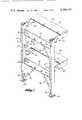
- FIG. 1is a fragmentary, isometric view of a shelving system constructed according to the present invention with portions broken away for clarity;
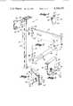
- FIG. 2is an enlarged, exploded, fragmentary, isometric view of the present invention specifically illustrating the manner in which the components of the shelving system are interconnected;
- FIG. 3is an enlarged fragmentary isometric view specifically illustrating the configuration of the brace upper end portion prior to the locking tab being deformed into locking position;
- FIGS. 4 and 5are enlarged, fragmentary, isometric views of the present invention specifically illustrating the interconnection between the upper end portion of a brace and a cross member wherein the locking tab of the brace has been bent into locking position.
- a typical shelving system 10 constructed according to the best mode of the present inventionis illustrated as including a pair of rectangularly shaped, hollow, upright posts 12 spaced transversely apart from each other across the width of shelving system 10.
- Posts 12include a series of aligned, vertically elongate, rectangularly-shaped slots 14 extending vertically along each sidewall 16 of posts 12.
- pairs of aligned, vertically elongate, rectangularly-shaped slots 18are vertically spaced apart along the inside face wall 20 of post 12.
- a circular foot member 22is attached to the lower end of each post 12 to serve as a bearing pad for the post.
- posts 12are illustrated as being rectangular, they can be formed in other cross-sectional shapes such as square or circular.
- posts 12are formed from relatively light gauge steel material as compared to the material used to form posts of conventional shelving systems.
- Shelving system 10further includes elongate members 24 which extend along the length of the shelving system to interconnect adjacent posts 12 which, while not shown, will be understood to be identical to the posts 12 shown.
- each member 24 as shownincludes a relatively deep, vertically disposed outer flange 26, a relatively narrow web 28 extending transversely from the lower edge portion of flange 26 and a relatively shallow inner flange 30 extending upwardly from the edge portion of web 28 opposite flange 26 to lie in spaced, generally parallel, relationship to flange 26.
- web 28 and flange 30is to strengthen and give rigidity to the member 24 and thus other configurations, such as a simple V-shaped flange, could be used to accomplish the same purpose.
- a pair of vertically aligned and vertically spaced, downwardly open hooks 32are formed at each end portion of longitudinal members 24.
- Hooks 32which form an extension of flange 26 are of a width slightly narrower and of a depth slightly shorter than the width and length of side slots 14 of posts 12 and thus are slidably insertable within the side slots. Once disposed within slots 14, longitudinal member 24 can be pushed downwardly so that hooks 32 snugly engage with the portion of sidewall 16 immediately below the slots to thereby interconnect the longitudinal member with post 12.
- shelving system 10also includes flat panels 34 which rest on top of outer flange 26 of longitudinal members 24 to serve as the shelf surfaces.
- Panels 34include downwardly extending flanges which overlie outer flanges 26 of member 24.
- Panels 34may be formed from lengths of wooden material, sheets of steel or other appropriate materials.
- panelsmay be bolted, clipped or otherwise affixed to longitudinal members 24.
- panelscan be sized to rest on top of inner flanges 30 of longitudinal members 24 so that outer flanges 26 serve to constrain the panels from shifting.
- each cross member 36is formed in a Z-shaped cross section having a relatively deep web 38 and relatively narrow upper and lower flanges 40 and 42, respectively, extending in opposite directions transversely from the web.
- a pair of vertically aligned, vertically spaces apart, downwardly open hooks 44extend longitudinally outwardly from each end of web 38. Hooks 44 are sized to slidably extend through post face slots 18 and then downwardly engage with the portions of face wall 20 disposed below slots 18.
- the above-described components of shelving system 10are formed from relatively light gauge material in comparison to conventional shelving system components.
- shelving system 10also includes elongate braces 46 which diagonally interconnect posts 12 with cross members 36.
- Each brace 46includes a flat, relatively narrow, elongate intermediate portion 48 and a hooked lower end portion 50 forming an extension of the intermediate portion.
- Lower end portion 50is disposed coplanar with intermediate portion 48 and defines a relatively narrow, groove 52 extending diagonally to the length of the brace. Groove 52 is open in the upward direction as shown in FIG. 2.
- Lower end portion 50is sized to slidably extend within the lower slot of the pair of face slots 18 located next below the pair of face slots with which corresponding cross member 36 engages. Once brace lower end portion 50 is inserted laterally within slot 18, brace 26 can be lifted upwardly to lock groove 52 with the portion of face wall 20 extending above the slot.
- the sides of slot 52are shown slanted upwardly slightly in FIG. 2, in another preferred embodiment the sides of slot 52 are vertical and the width of slot 52 between these sides is sized to be only slightly larger than the thickness of face wall 20. In this configuration, when the brace 46 is moved upwardly after the lower end portion 50 is inserted laterally into slot 18, the sides of the slot snugly engage face wall 20 thus preventing lateral movement of the brace with respect to face wall 20.
- Brace 46extends transversely outwardly and diagonally upwardly from post 12 to interconnect with cross member 36 at a location spaced from the end of the cross member. As best illustrated in FIGS. 4 and 5, the upper section of brace intermediate portion 48 partially overlaps cross member web 38. Brace 46 includes an upper end portion 54 which extends transversely to intermediate portion 48 to extend through an elongate, rectangularly shaped, diagonally disposed slot 56 formed within web 38 of cross member 36. For ease of manufacture, upper end portion 54 is preferably of the same width as intermediate portion 48 and is formed by bending over the end of brace 46.
- brace upper end portionincludes a base section 58 interconnected with and extending across approximately one half of the width of the base intermediate portion 48.
- the brace upper end portionalso includes a tab 60 disposed nominally coplanar with, and extending outwardly from, base section 58.
- Tab 60terminates at a tip 59 corresponding to the outward location of the side edge 61 of brace intermediate portion 48 so that the tab does not extend beyond the width of the brace intermediate portion.
- Tab 60which is narrower than the length of base section 58 includes a side edge portion 62 spaced from base intermediate portion 48 to thereby define a narrow gap 63 therebetween.
- Gap 63is not of uniform width, but is slightly narrower than the thickness of cross member web 38 at the intersection of tab 60 and base 58 and is slightly wider than the thickness of the cross member web at tab tip 59.
- brace 46can be conveniently locked in place by bending over tab 60 relative to base section 58 by use of conventional tools, such as a hammer or a pair of pliers. Because the width of tab 60 is substantially narrower than the length of base 58, when tab 60 is struck, for instance with a hammer, the tab will bend at its intersection with base section 58 rather than causing the base section itself to deform. Also, because the width of gap 63 at the intersection of tab 60 and base 58 is slightly narrower than the thickness of cross member web 38, the cross member is tightly clamped between tab 60 and base 58 with tab edge 62 actually bearing against the adjacent face of the web.
- brace 48when bent over into locking position, tab 60 prevents disengagement of brace 48 from cross member 36 even if the brace is highly loaded in tension due to the heavy loads carried by shelving system 20. Also, the overlapping of web 38 of cross member 36 by brace intermediate portion 48 and the pressing of tab side edge 62 against the adjacent surface 64 of web 38 prevents brace 46 from rotating about its longitudinal axis. As a consequence, brace 48 enhances the rigidity of shelving system 10 to the extent that even though the shelving system is constructed from lighter weight and smaller dimension components than previously usable in such shelving, it is capable of safely carrying as large a load.
- brace 48to not only act in tension, as would be commonly expected, but to also act in compression to provide stability to the shelving.
- the lower end 50 of brace 46is first moved laterally into slot 18 in the face 20 of post 12.
- the upper bent end 54 of the braceis positioned vertically below slot 56 in cross member 36.
- brace upper end 54is brought into register with slot 56 such that a small lateral force on brace 48, such as a force exerted by the pressure of the assembler's thumb, causes end 54 to snap into slot 56.
- slot 56is only slightly larger in thickness than the bent end 54 of brace 46, when the shelving is rocked or caused to tilt during loading, a compression force may be borne by brace 46 exerted between the outer side of slot 52 in the lower end of the brace as it bears on the outside of face wall 20 and the outer surface of bent end 54 as it bears on the adjacent edge of cross member slot 56.
- pairs of braces 46 associated with each cross member 36are designed to normally function in tension and the present design provides a unique non-bolted or welded brace which may also function in compression in certain situations.
- tab 16can be conveniently straightened with, for instance, a pair of pliers so that brace 46 can be disengaged from cross member 36 and posts 12. Thereafter, the ends of cross members 36 can be lifted upwardly to disengage hooks 48 from face wall 20 and then the hooks can be slidably disengaged from slots 18. The same procedure is used to disassemble longitudinal members 24 from posts 12.
Landscapes
- Assembled Shelves (AREA)
Abstract
Description
Claims (5)
Priority Applications (3)
| Application Number | Priority Date | Filing Date | Title |
|---|---|---|---|
| US06/228,173US4390103A (en) | 1981-01-23 | 1981-01-23 | Shelving system |
| CA000393935ACA1171389A (en) | 1981-01-23 | 1982-01-12 | Shelving system |
| GB8201324AGB2091540B (en) | 1981-01-23 | 1982-01-18 | Shelving system |
Applications Claiming Priority (1)
| Application Number | Priority Date | Filing Date | Title |
|---|---|---|---|
| US06/228,173US4390103A (en) | 1981-01-23 | 1981-01-23 | Shelving system |
Publications (1)
| Publication Number | Publication Date |
|---|---|
| US4390103Atrue US4390103A (en) | 1983-06-28 |
Family
ID=22856107
Family Applications (1)
| Application Number | Title | Priority Date | Filing Date |
|---|---|---|---|
| US06/228,173Expired - LifetimeUS4390103A (en) | 1981-01-23 | 1981-01-23 | Shelving system |
Country Status (3)
| Country | Link |
|---|---|
| US (1) | US4390103A (en) |
| CA (1) | CA1171389A (en) |
| GB (1) | GB2091540B (en) |
Cited By (24)
| Publication number | Priority date | Publication date | Assignee | Title |
|---|---|---|---|---|
| US5330066A (en)* | 1992-08-31 | 1994-07-19 | Kim Manufacturing Company | Two tier frame |
| US5432626A (en)* | 1992-03-12 | 1995-07-11 | Hitachi, Ltd. | Liquid crystal display device with shield casing connected to frame holding the display above lower casing holding light source |
| US6481582B1 (en) | 2001-06-04 | 2002-11-19 | Cooper Technologies Company | Rack |
| US20050189532A1 (en)* | 2004-03-01 | 2005-09-01 | Gasaway Mark S. | Joint connection and applications |
| US20100101820A1 (en)* | 2008-01-07 | 2010-04-29 | Chatsworth Products, Inc. | Cable management accessories |
| US20100252521A1 (en)* | 2009-04-03 | 2010-10-07 | Protrend Co., Ltd | Sectional rack |
| US20100288477A1 (en)* | 2009-05-14 | 2010-11-18 | Tecumseh Products Company | Condensing unit attachment feature |
| US20130067734A1 (en)* | 2010-05-29 | 2013-03-21 | Muhlack Kiel Gmbh | Assembly Kit for Building a Rack |
| US20130213918A1 (en)* | 2012-02-13 | 2013-08-22 | Madix, Inc. | Shelving, Furniture, and Display Apparatus |
| US9316004B1 (en)* | 2014-12-01 | 2016-04-19 | Michael Hatzinikolas | Support bracket assembly and method |
| US9447585B2 (en)* | 2014-12-01 | 2016-09-20 | Michael Hatzinikolas | Support bracket apparatus |
| US10323419B2 (en) | 2015-04-16 | 2019-06-18 | Fero Corporation | Support bracket apparatus |
| KR102008128B1 (en)* | 2019-05-02 | 2019-08-06 | 주식회사 제이빅 | Sectional shelf |
| WO2020235746A1 (en)* | 2019-05-17 | 2020-11-26 | (주)태보산업 | Non-bolt prefabricated angle structure and angle assembly using same |
| US11118358B2 (en) | 2019-05-30 | 2021-09-14 | Fero Corporation | Support bracket assembly and method |
| US11162265B2 (en) | 2020-04-06 | 2021-11-02 | Fero Corporation | Support bracket assembly and method |
| US11255091B2 (en) | 2018-12-03 | 2022-02-22 | Fero Corporation | Support bracket apparatus |
| US20220159865A1 (en)* | 2020-11-16 | 2022-05-19 | Sebastian Sanchez | Modular Switch Rack |
| US20220354249A1 (en)* | 2021-05-07 | 2022-11-10 | Gail Winifred Nichols | Modular adjustable storage organizer |
| US11560709B2 (en) | 2021-06-11 | 2023-01-24 | Fero Corporation | Support bracket hanger assembly and method |
| US11674316B2 (en) | 2021-01-29 | 2023-06-13 | Hohmann & Barnard, Inc. | Facade support system |
| USD998377S1 (en)* | 2022-11-15 | 2023-09-12 | Zijiang Yang | Combination panels for horizontal wall mount rack |
| US12158007B2 (en) | 2020-01-31 | 2024-12-03 | Hohmann & Barnard, Inc. | Facade support system |
| US12398568B2 (en) | 2023-04-25 | 2025-08-26 | Hohmann & Barnard, Inc. | Thermal brick support mounting bracket |
Families Citing this family (2)
| Publication number | Priority date | Publication date | Assignee | Title |
|---|---|---|---|---|
| GB2197183A (en)* | 1986-10-30 | 1988-05-18 | Stockrail Services Ltd | Racking system |
| GB201715204D0 (en)* | 2017-09-20 | 2017-11-01 | Lopez Juan Ramon | A modular, movable, versatile, vertical greenhouse |
Citations (14)
| Publication number | Priority date | Publication date | Assignee | Title |
|---|---|---|---|---|
| US895578A (en)* | 1907-09-11 | 1908-08-11 | John Calvin Mcnamara | Awning-support. |
| US1634128A (en)* | 1926-08-16 | 1927-06-28 | Keyes Fibre Co | Apparatus for molding articles from pulp |
| US1795060A (en)* | 1931-03-03 | Ttcts | ||
| US1808082A (en)* | 1928-12-26 | 1931-06-02 | Carl A Thompson | Scaffold |
| US2279325A (en)* | 1941-04-29 | 1942-04-14 | Kaldizar Lewis | Gun rack |
| US2530632A (en)* | 1948-05-18 | 1950-11-21 | Sydney M Scherstuhl | Foldable rack |
| US2712200A (en)* | 1952-09-24 | 1955-07-05 | Harry S Dearling | Shape-retaining interlocking toy element |
| US2972506A (en)* | 1958-04-04 | 1961-02-21 | Burroughs Mfg Co | Bench furniture |
| US3050160A (en)* | 1961-03-09 | 1962-08-21 | Sears Roebuck & Co | Sheet metal connection and method for effecting the same |
| US3193060A (en)* | 1962-05-29 | 1965-07-06 | Park Wallace Sidney | Structural bracing member |
| US3490604A (en)* | 1967-05-19 | 1970-01-20 | Unarco Industries | Safety hook for knockdown rack |
| US3604176A (en)* | 1969-10-24 | 1971-09-14 | Armco Steel Corp | Self-fastening spacer for structural members |
| US4063835A (en)* | 1977-01-27 | 1977-12-20 | E-Z Rect-Metal Products Ltd. | Frame construction |
| US4129279A (en)* | 1978-01-09 | 1978-12-12 | Favorite Manufacturing, Inc. | Truss clip |
- 1981
- 1981-01-23USUS06/228,173patent/US4390103A/ennot_activeExpired - Lifetime
- 1982
- 1982-01-12CACA000393935Apatent/CA1171389A/ennot_activeExpired
- 1982-01-18GBGB8201324Apatent/GB2091540B/ennot_activeExpired
Patent Citations (14)
| Publication number | Priority date | Publication date | Assignee | Title |
|---|---|---|---|---|
| US1795060A (en)* | 1931-03-03 | Ttcts | ||
| US895578A (en)* | 1907-09-11 | 1908-08-11 | John Calvin Mcnamara | Awning-support. |
| US1634128A (en)* | 1926-08-16 | 1927-06-28 | Keyes Fibre Co | Apparatus for molding articles from pulp |
| US1808082A (en)* | 1928-12-26 | 1931-06-02 | Carl A Thompson | Scaffold |
| US2279325A (en)* | 1941-04-29 | 1942-04-14 | Kaldizar Lewis | Gun rack |
| US2530632A (en)* | 1948-05-18 | 1950-11-21 | Sydney M Scherstuhl | Foldable rack |
| US2712200A (en)* | 1952-09-24 | 1955-07-05 | Harry S Dearling | Shape-retaining interlocking toy element |
| US2972506A (en)* | 1958-04-04 | 1961-02-21 | Burroughs Mfg Co | Bench furniture |
| US3050160A (en)* | 1961-03-09 | 1962-08-21 | Sears Roebuck & Co | Sheet metal connection and method for effecting the same |
| US3193060A (en)* | 1962-05-29 | 1965-07-06 | Park Wallace Sidney | Structural bracing member |
| US3490604A (en)* | 1967-05-19 | 1970-01-20 | Unarco Industries | Safety hook for knockdown rack |
| US3604176A (en)* | 1969-10-24 | 1971-09-14 | Armco Steel Corp | Self-fastening spacer for structural members |
| US4063835A (en)* | 1977-01-27 | 1977-12-20 | E-Z Rect-Metal Products Ltd. | Frame construction |
| US4129279A (en)* | 1978-01-09 | 1978-12-12 | Favorite Manufacturing, Inc. | Truss clip |
Cited By (36)
| Publication number | Priority date | Publication date | Assignee | Title |
|---|---|---|---|---|
| US5432626A (en)* | 1992-03-12 | 1995-07-11 | Hitachi, Ltd. | Liquid crystal display device with shield casing connected to frame holding the display above lower casing holding light source |
| US5330066A (en)* | 1992-08-31 | 1994-07-19 | Kim Manufacturing Company | Two tier frame |
| US6481582B1 (en) | 2001-06-04 | 2002-11-19 | Cooper Technologies Company | Rack |
| US20050189532A1 (en)* | 2004-03-01 | 2005-09-01 | Gasaway Mark S. | Joint connection and applications |
| US7344122B2 (en)* | 2004-03-01 | 2008-03-18 | Gasaway Mark S | Joint connection and applications |
| US8330043B2 (en) | 2008-01-07 | 2012-12-11 | Chatsworth Products, Inc. | Cable management accessories |
| US20100101820A1 (en)* | 2008-01-07 | 2010-04-29 | Chatsworth Products, Inc. | Cable management accessories |
| US20100252521A1 (en)* | 2009-04-03 | 2010-10-07 | Protrend Co., Ltd | Sectional rack |
| US8038021B2 (en)* | 2009-04-03 | 2011-10-18 | Protrend Co., Ltd | Sectional rack |
| US20100288477A1 (en)* | 2009-05-14 | 2010-11-18 | Tecumseh Products Company | Condensing unit attachment feature |
| US20130067734A1 (en)* | 2010-05-29 | 2013-03-21 | Muhlack Kiel Gmbh | Assembly Kit for Building a Rack |
| US8875910B2 (en)* | 2010-05-29 | 2014-11-04 | Muhlack Kiel Gmbh | Assembly kit for building a rack |
| US20130213918A1 (en)* | 2012-02-13 | 2013-08-22 | Madix, Inc. | Shelving, Furniture, and Display Apparatus |
| US11629504B2 (en) | 2014-12-01 | 2023-04-18 | Fero Corporation | Support bracket apparatus |
| US11078672B2 (en) | 2014-12-01 | 2021-08-03 | Fero Corporation | Support bracket apparatus |
| US10294676B2 (en) | 2014-12-01 | 2019-05-21 | Fero Corporation | Support bracket assembly and method |
| US9316004B1 (en)* | 2014-12-01 | 2016-04-19 | Michael Hatzinikolas | Support bracket assembly and method |
| US9447585B2 (en)* | 2014-12-01 | 2016-09-20 | Michael Hatzinikolas | Support bracket apparatus |
| US11041315B2 (en) | 2014-12-01 | 2021-06-22 | Fero Corporation | Support bracket apparatus |
| US10323419B2 (en) | 2015-04-16 | 2019-06-18 | Fero Corporation | Support bracket apparatus |
| US11255091B2 (en) | 2018-12-03 | 2022-02-22 | Fero Corporation | Support bracket apparatus |
| US12241255B2 (en) | 2018-12-03 | 2025-03-04 | Fero Corporation | Support bracket apparatus |
| KR102008128B1 (en)* | 2019-05-02 | 2019-08-06 | 주식회사 제이빅 | Sectional shelf |
| WO2020235746A1 (en)* | 2019-05-17 | 2020-11-26 | (주)태보산업 | Non-bolt prefabricated angle structure and angle assembly using same |
| US11118358B2 (en) | 2019-05-30 | 2021-09-14 | Fero Corporation | Support bracket assembly and method |
| US12158007B2 (en) | 2020-01-31 | 2024-12-03 | Hohmann & Barnard, Inc. | Facade support system |
| US11162265B2 (en) | 2020-04-06 | 2021-11-02 | Fero Corporation | Support bracket assembly and method |
| US11952783B2 (en) | 2020-04-06 | 2024-04-09 | Fero Corporation | Support bracket assembly and method |
| US20220159865A1 (en)* | 2020-11-16 | 2022-05-19 | Sebastian Sanchez | Modular Switch Rack |
| US11758683B2 (en)* | 2020-11-16 | 2023-09-12 | Sebastian Sanchez | Modular switch rack |
| US11674316B2 (en) | 2021-01-29 | 2023-06-13 | Hohmann & Barnard, Inc. | Facade support system |
| US20220354249A1 (en)* | 2021-05-07 | 2022-11-10 | Gail Winifred Nichols | Modular adjustable storage organizer |
| US12134889B2 (en) | 2021-06-11 | 2024-11-05 | Fero Corporation | Support bracket hanger assembly and method |
| US11560709B2 (en) | 2021-06-11 | 2023-01-24 | Fero Corporation | Support bracket hanger assembly and method |
| USD998377S1 (en)* | 2022-11-15 | 2023-09-12 | Zijiang Yang | Combination panels for horizontal wall mount rack |
| US12398568B2 (en) | 2023-04-25 | 2025-08-26 | Hohmann & Barnard, Inc. | Thermal brick support mounting bracket |
Also Published As
| Publication number | Publication date |
|---|---|
| GB2091540A (en) | 1982-08-04 |
| CA1171389A (en) | 1984-07-24 |
| GB2091540B (en) | 1984-08-30 |
Similar Documents
| Publication | Publication Date | Title |
|---|---|---|
| US4390103A (en) | Shelving system | |
| US8016141B2 (en) | Locking cross bar | |
| US4173934A (en) | Shelving structure | |
| US4342397A (en) | Fastenings for storage racks | |
| US3545626A (en) | Storage structure | |
| US4821649A (en) | Sheet metal shelving | |
| US5628415A (en) | Storage rack and safety bars for use therein | |
| US5259477A (en) | Collapsible scaffold bracket | |
| US3127995A (en) | Adjustable pallet rack | |
| US4545490A (en) | Safety steel angle assembly rack | |
| US20120067838A1 (en) | Industrial frame rack support assembly | |
| US3217894A (en) | Locking mechanism | |
| US4023683A (en) | Internally reinforced load carrying member | |
| US3523613A (en) | Storage rack | |
| US20170238703A1 (en) | Supporting Beam and Net Shelf for Shelving Apparatus | |
| US20170238710A1 (en) | Dual Side Post for Multiple Shelving Apparatus | |
| US3879144A (en) | Connector mechanism | |
| US6126127A (en) | Bracket assembly | |
| US4030612A (en) | Pallet racks | |
| KR20100008790U (en) | Assembling rack | |
| US20230189993A1 (en) | Shelving unit tie bar | |
| US5941486A (en) | Bracket assembly | |
| US4063835A (en) | Frame construction | |
| JPS59116Y2 (en) | coupling device | |
| US2992744A (en) | Shelving assembly |
Legal Events
| Date | Code | Title | Description |
|---|---|---|---|
| AS | Assignment | Owner name:E-Z-RECT METAL PRODUCTS LTD., 94 RIVERSIDE DRIVE, Free format text:ASSIGNMENT OF ASSIGNORS INTEREST.;ASSIGNOR:HUSBAND WALLACE T.;REEL/FRAME:003844/0339 Effective date:19810331 | |
| STCF | Information on status: patent grant | Free format text:PATENTED CASE | |
| MAFP | Maintenance fee payment | Free format text:PAYMENT OF MAINTENANCE FEE, 4TH YEAR, PL 96-517 (ORIGINAL EVENT CODE: M170); ENTITY STATUS OF PATENT OWNER: SMALL ENTITY Year of fee payment:4 | |
| FEPP | Fee payment procedure | Free format text:PAYOR NUMBER ASSIGNED (ORIGINAL EVENT CODE: ASPN); ENTITY STATUS OF PATENT OWNER: SMALL ENTITY | |
| AS | Assignment | Owner name:E-Z-RECT MANUFACTURING LTD., SUITE 520 - 701 WEST Free format text:ASSIGNMENT OF ASSIGNORS INTEREST.;ASSIGNOR:E-Z-RECT METAL PRODUCTS LTD.;REEL/FRAME:004649/0191 Effective date:19860605 Owner name:E-Z-RECT MANUFACTURING LTD., A BRITISH COLUMBIA, C Free format text:ASSIGNMENT OF ASSIGNORS INTEREST;ASSIGNOR:E-Z-RECT METAL PRODUCTS LTD.;REEL/FRAME:004649/0191 Effective date:19860605 | |
| MAFP | Maintenance fee payment | Free format text:PAYMENT OF MAINTENANCE FEE, 8TH YEAR, PL 96-517 (ORIGINAL EVENT CODE: M171); ENTITY STATUS OF PATENT OWNER: SMALL ENTITY Year of fee payment:8 | |
| FEPP | Fee payment procedure | Free format text:PAYOR NUMBER ASSIGNED (ORIGINAL EVENT CODE: ASPN); ENTITY STATUS OF PATENT OWNER: SMALL ENTITY Free format text:PAYER NUMBER DE-ASSIGNED (ORIGINAL EVENT CODE: RMPN); ENTITY STATUS OF PATENT OWNER: SMALL ENTITY | |
| MAFP | Maintenance fee payment | Free format text:PAYMENT OF MAINTENANCE FEE, 12TH YR, SMALL ENTITY (ORIGINAL EVENT CODE: M285); ENTITY STATUS OF PATENT OWNER: SMALL ENTITY Year of fee payment:12 |