US4390038A - Magnetically locked valve - Google Patents
Magnetically locked valveDownload PDFInfo
- Publication number
- US4390038A US4390038AUS06/348,423US34842382AUS4390038AUS 4390038 AUS4390038 AUS 4390038AUS 34842382 AUS34842382 AUS 34842382AUS 4390038 AUS4390038 AUS 4390038A
- Authority
- US
- United States
- Prior art keywords
- valve
- actuator shaft
- shaft section
- fire hydrant
- shaped magnet
- Prior art date
- Legal status (The legal status is an assumption and is not a legal conclusion. Google has not performed a legal analysis and makes no representation as to the accuracy of the status listed.)
- Expired - Lifetime
Links
- 239000012530fluidSubstances0.000claimsabstractdescription12
- 229910000831SteelInorganic materials0.000claimsdescription2
- 230000008878couplingEffects0.000claimsdescription2
- 238000010168coupling processMethods0.000claimsdescription2
- 238000005859coupling reactionMethods0.000claimsdescription2
- 239000010959steelSubstances0.000claimsdescription2
- XLYOFNOQVPJJNP-UHFFFAOYSA-NwaterSubstancesOXLYOFNOQVPJJNP-UHFFFAOYSA-N0.000description5
- 238000010276constructionMethods0.000description3
- 238000005266castingMethods0.000description2
- 239000003208petroleumSubstances0.000description2
- 230000000694effectsEffects0.000description1
- 230000005484gravityEffects0.000description1
- 239000000463materialSubstances0.000description1
- 238000009428plumbingMethods0.000description1
- 238000011144upstream manufacturingMethods0.000description1
Images

Classifications
- E—FIXED CONSTRUCTIONS
- E03—WATER SUPPLY; SEWERAGE
- E03B—INSTALLATIONS OR METHODS FOR OBTAINING, COLLECTING, OR DISTRIBUTING WATER
- E03B9/00—Methods or installations for drawing-off water
- E03B9/02—Hydrants; Arrangements of valves therein; Keys for hydrants
- Y—GENERAL TAGGING OF NEW TECHNOLOGICAL DEVELOPMENTS; GENERAL TAGGING OF CROSS-SECTIONAL TECHNOLOGIES SPANNING OVER SEVERAL SECTIONS OF THE IPC; TECHNICAL SUBJECTS COVERED BY FORMER USPC CROSS-REFERENCE ART COLLECTIONS [XRACs] AND DIGESTS
- Y10—TECHNICAL SUBJECTS COVERED BY FORMER USPC
- Y10S—TECHNICAL SUBJECTS COVERED BY FORMER USPC CROSS-REFERENCE ART COLLECTIONS [XRACs] AND DIGESTS
- Y10S403/00—Joints and connections
- Y10S403/01—Magnetic
- Y—GENERAL TAGGING OF NEW TECHNOLOGICAL DEVELOPMENTS; GENERAL TAGGING OF CROSS-SECTIONAL TECHNOLOGIES SPANNING OVER SEVERAL SECTIONS OF THE IPC; TECHNICAL SUBJECTS COVERED BY FORMER USPC CROSS-REFERENCE ART COLLECTIONS [XRACs] AND DIGESTS
- Y10—TECHNICAL SUBJECTS COVERED BY FORMER USPC
- Y10T—TECHNICAL SUBJECTS COVERED BY FORMER US CLASSIFICATION
- Y10T137/00—Fluid handling
- Y10T137/5327—Hydrant type
- Y10T137/5456—With casing
- Y10T137/5468—Cap, cover or hood
- Y—GENERAL TAGGING OF NEW TECHNOLOGICAL DEVELOPMENTS; GENERAL TAGGING OF CROSS-SECTIONAL TECHNOLOGIES SPANNING OVER SEVERAL SECTIONS OF THE IPC; TECHNICAL SUBJECTS COVERED BY FORMER USPC CROSS-REFERENCE ART COLLECTIONS [XRACs] AND DIGESTS
- Y10—TECHNICAL SUBJECTS COVERED BY FORMER USPC
- Y10T—TECHNICAL SUBJECTS COVERED BY FORMER US CLASSIFICATION
- Y10T137/00—Fluid handling
- Y10T137/6851—With casing, support, protector or static constructional installations
- Y10T137/7043—Guards and shields
- Y10T137/7062—Valve guards
- Y—GENERAL TAGGING OF NEW TECHNOLOGICAL DEVELOPMENTS; GENERAL TAGGING OF CROSS-SECTIONAL TECHNOLOGIES SPANNING OVER SEVERAL SECTIONS OF THE IPC; TECHNICAL SUBJECTS COVERED BY FORMER USPC CROSS-REFERENCE ART COLLECTIONS [XRACs] AND DIGESTS
- Y10—TECHNICAL SUBJECTS COVERED BY FORMER USPC
- Y10T—TECHNICAL SUBJECTS COVERED BY FORMER US CLASSIFICATION
- Y10T137/00—Fluid handling
- Y10T137/7069—With lock or seal
- Y10T137/7131—Common lock and valve actuator
- Y10T137/7225—Mechanical movement between lock and valve
- Y—GENERAL TAGGING OF NEW TECHNOLOGICAL DEVELOPMENTS; GENERAL TAGGING OF CROSS-SECTIONAL TECHNOLOGIES SPANNING OVER SEVERAL SECTIONS OF THE IPC; TECHNICAL SUBJECTS COVERED BY FORMER USPC CROSS-REFERENCE ART COLLECTIONS [XRACs] AND DIGESTS
- Y10—TECHNICAL SUBJECTS COVERED BY FORMER USPC
- Y10T—TECHNICAL SUBJECTS COVERED BY FORMER US CLASSIFICATION
- Y10T70/00—Locks
- Y10T70/70—Operating mechanism
- Y10T70/7051—Using a powered device [e.g., motor]
- Y10T70/7057—Permanent magnet
Definitions
- the present inventionrelates generally to a locking arrangement for preventing unauthorized operation of a flow control valve, and more particularly pertains to a magnetically locked fluid valve designed for a fire hydrant to prevent unauthorized usage thereof.
- Fire hydrants in prevelant usage todaycomprise a stand pipe which extends upwardly from an elbow which is connected to the main water supply pipe line.
- a control valveis located at the juncture between the bottom of the stand pipe and the elbow for controlling the flow of water to the fire hydrant.
- the stand pipeis provided with an above ground portion of barrel which includes at least one steamer nozzle or outlet nozzle extending laterally therefrom.
- a control valve operating rodalso extends upwardly from the control valve through the barrel portion to the top thereof whereat it is accessible to authorized personnel for opening the control valve when desired, such as in the case of a fire when a fire hose is connected to the fire hydrant.
- Unauthorized personsare able to open the fire hydrant by gaining access to an operating nut at the upper end of the operating rod and opening the control valve.
- the hydrantincludes a valve located within the barrel portion and provided with a valve member which is spring biased to a closed position extending across the upstream end of the outlet nozzle.
- a valve actuatoris provided for moving the valve member from its closed position to its open position against the bias of the spring means.
- a collaris adapted to be mounted on the fire hydrant by authorized persons in a position surrounding the outlet nozzle.
- the collarcarries a valve actuating member which is arranged to move into the outlet nozzle to contact the valve member to move it from a closed position to an open position as the collar is mounted on the fire hydrant.
- this arrangementis rather complex, and would be an extremely expensive system to emplement when considering all of the replacement fire hydrants and hose collars required thereby.
- a further object of the subject inventionis the provision of a magnetically locked valve for a fire hydrant which can be retrofitted to existing hydrants with a minimal replacement of parts.
- the present inventionprovides a magnetically locked fluid valve having a valve seat and a valve element movable relative thereto between open and closed positions.
- a rotatably mounted valve actuator shaftis externally accessible on the locked valve, and when coupled thereto allows the valve to be opened or closed.
- a magnetic lockis provided to couple the actuator shaft to the valve in response to a shaped magnet being properly positioned relative thereto, and also to decouple the actuator shaft from the valve responsive to the magnet being removed.
- the magnetically locked fluid valveis particularly designed to be utilized in combination with a fire hydrant to prevent unauthorized usage thereof, but should also have utility in other areas wherein unauthorized control of a fluid valve may be a problem.
- the fire hydrantincludes an operating nut mounted on top thereof at one end of the actuator shaft, and the magnetic lock is located in immediate proximity thereto.
- the shaped magnethas an opening adapted to be placed around the end of the actuator shaft adjacent to the nut such that a wrench can be applied thereto after the shaped magnet is positioned on the shaft.
- the magnetic lockincludes magnetic tumblers which are shifted in position in response to placement of the magnet around the actuator shaft, and in a preferred embodiment the magnetic lock actually forms a part of the actuator shaft.
- the actuator shafthas an upper section by the operating nut and a lower section coupled to the valve.
- the magnetic lockis positioned between the upper and lower shaft sections, such that the upper shaft section is freely rotatable relative to the lower section when the magnet is removed, but is locked relative thereto when the magnet is placed around the actuator shaft.
- the magnetic tumblersare steel bars axially displaceable along the shaft in axial recesses therein, and extend between axial recesses in the upper and lower shaft sections when the shaped magnet is placed around the shaft, thereby coupling those elements together.
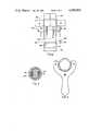
- FIG. 1is an elevational partially sectional view of an exemplary embodiment of a magnetically locked fire hydrant constructed pursuant to the teachings of the present invention
- FIG. 2illustrates an enlarged elevational view of the magnetic locking feature of the present invention.
- FIG. 3is a sectional view along line 3--3 in FIG. 2 and illustrates further details of construction of the magnetic lock
- FIG. 4is a plan view of the magnetic lock with a shaped magnet applied thereto.
- a fire hydrant in accordance with the present inventioncomprises a usual stand pipe 10 which is connected at its bottom end to a conventional elbow casting 12 located underground and connected to the main water supply pipe 13 as is conventional in the art.
- the hydrantcomprises a barrel portion 14, which has a laterally extending steamer or outlet nozzle 16 mounted thereon and having a circular opening 18.
- the nozzle 16is provided with external threads 20 which are engageable by a cap 22 for closing the nozzle 16 when the fire hydrant is not in use.
- a top operating nut 24which is angular and projects above a hood 26 threadedly mounted on the upper end of the barrel 14.
- the operating nut 24is connected to an actuating shaft 28 connected to a conventional plug valve 30 at the lower end of the stand pipe 10 for controlling flow from the elbow casting into the lower end of the stand pipe 10.
- a drip rod 32which extends from the upper end of the barrel 14 downwardly to control a drip port (not shown), the construction of which is conventional in the art, and accordingly is not explained further herein.
- a fire hydrant of this typeis controlled by applying a suitable wrench to operating nut 24, and turning the nut which in turn rotates an internally threaded actuator shaft 34 relative to an externally threaded actuator shaft 36 which in turn lowers or raises actuator shaft 28 to open or close plug valve 30.
- the present inventionoperates in substantially the same manner provided a shaped magnetic key 38 is properly positioned below operating nut 24 in proximity to a magnetic lock 40 forming a part of actuator shaft 34.
- FIG. 2illustrates an enlarged view in phantom of the magnetic lock 40 illustrating further details of construction thereof.
- Actuator shaft 34is divided into an upper shaft section 42 having a coaxial cylindrical bore in its lower end and a lower shaft section 44 having a reduced diameter cylindrical end 46 starting at an annular shoulder 47, which projects into the cylindrical bore in the upper shaft section 42.
- Actuating shaft sections 42 and 44are normally constructed from nonmagnetic materials for reasons as will become clear in the subsequent explanation.
- Reduced diameter cylindrical end 46can have an annular groove 48 formed around its circumference and upper shaft section 42 can have one or more corresponding groove sections 49 formed therein such that pins such as a sectional C pin can be introduced between the groove 48 and groove sections 49 to anchor the upper and lower shaft sections 42 and 44 against axial movement therebetween while still allowing relative rotational movement.
- the upper end of reduced diameter cylindrical section 46has one or more axial recesses 50 formed therein which are rectangular in cross sectional shape in the illustrated embodiment.
- the immediately adjacent end of the coaxial bore in the upper shaft section 42has corresponding axial recesses 52 formed therein which may or may not be radially aligned depending upon the relative rotational positions of the shaft sections 42 and 44.
- Magnetic detents or tumblers 54shown as having a rectangular cross sectional profile, are positioned in axial recesses 50, and are axially movable therein (under the influence of magnetic key 38) in an upward direction to extend between recesses 50 and 52 provided the recesses are rotationally aligned with each other.
- tumblers 54rest fully in recesses 50 under the influence of gravity as shown on the right side of FIG. 2. If a wrench were applied to operating nut 24 in this condition, upper shaft section 42 would turn freely relative to lower shaft section 44, and it would appear to the person utilizing the wrench that the fire hydrant is broken.
- other shaped detents 54particularly round, and correspondingly shaped recesses 50 and 52 can be utilized.
- the pattern and number of the recessescan vary from embodiment to embodiment.
- the arrangement of magnets on key 38depends to a degree upon the pattern and number of the recesses.
- the magnetic keycan be combined with a wrench to form in effect a magnetically keyed wrench.
- the pesent inventioncan be easily and nonexpensively retrofitted to existing fire hydrants by a simple replacement of the standard internally threaded actuator shaft 34 with a shaft 34 constructed pursuant to the teachings of the present invention having a magnetic lock 40 incorporated therein.
Landscapes
- Health & Medical Sciences (AREA)
- Life Sciences & Earth Sciences (AREA)
- Engineering & Computer Science (AREA)
- Hydrology & Water Resources (AREA)
- Public Health (AREA)
- Water Supply & Treatment (AREA)
- Preventing Unauthorised Actuation Of Valves (AREA)
Abstract
Description
Claims (6)
Priority Applications (1)
| Application Number | Priority Date | Filing Date | Title |
|---|---|---|---|
| US06/348,423US4390038A (en) | 1982-02-12 | 1982-02-12 | Magnetically locked valve |
Applications Claiming Priority (1)
| Application Number | Priority Date | Filing Date | Title |
|---|---|---|---|
| US06/348,423US4390038A (en) | 1982-02-12 | 1982-02-12 | Magnetically locked valve |
Publications (1)
| Publication Number | Publication Date |
|---|---|
| US4390038Atrue US4390038A (en) | 1983-06-28 |
Family
ID=23367982
Family Applications (1)
| Application Number | Title | Priority Date | Filing Date |
|---|---|---|---|
| US06/348,423Expired - LifetimeUS4390038A (en) | 1982-02-12 | 1982-02-12 | Magnetically locked valve |
Country Status (1)
| Country | Link |
|---|---|
| US (1) | US4390038A (en) |
Cited By (21)
| Publication number | Priority date | Publication date | Assignee | Title |
|---|---|---|---|---|
| US4620428A (en)* | 1983-02-10 | 1986-11-04 | Productive Instrument & Machine, Inc. | Lock and coupling for securing fire hydrants |
| US4671486A (en)* | 1986-06-23 | 1987-06-09 | Gabriel Giannini | Magnetic valve actuator |
| US4716922A (en)* | 1987-06-05 | 1988-01-05 | Camp John P | Magnetic fire hydrant guard |
| US4781211A (en)* | 1985-06-03 | 1988-11-01 | Cormier George J | Lock for a valve |
| US4790342A (en)* | 1987-11-30 | 1988-12-13 | Milton Segal | Fire hydrant valve actuator |
| US4827969A (en)* | 1988-09-30 | 1989-05-09 | Peter Lyasko | Cover for a hydrant |
| US5072750A (en)* | 1989-07-18 | 1991-12-17 | Ariah Poms | Fire hydrant closures |
| US5205312A (en)* | 1992-06-02 | 1993-04-27 | Magna-Loc Valve Corp. | Fire hydrant locking arrangement |
| US5596893A (en)* | 1995-12-28 | 1997-01-28 | Hydra-Shield Manufacturing, Inc. | Devices for securing fire hydrant valves |
| US6802338B1 (en) | 2003-10-14 | 2004-10-12 | Hydra-Shield Manufacturing, Inc. | Fire hydrant securing arrangements |
| US20070028967A1 (en)* | 2005-08-04 | 2007-02-08 | Mueller International, Inc. | Keyless fire hydrant protection system |
| US20070295406A1 (en)* | 2006-06-21 | 2007-12-27 | Mueller International, Inc. | Hydrant shoe with backflow prevention assembly |
| US20080143098A1 (en)* | 2006-11-07 | 2008-06-19 | Joerg Zimmermann | Magnetic fluid coupling assemblies and methods |
| US20080245420A1 (en)* | 2007-04-09 | 2008-10-09 | Tom Randy Davidson | Nozzle Attachment for Fire Hydrant |
| USD591831S1 (en) | 2007-06-12 | 2009-05-05 | Mueller International, Inc. | Hydrant shoe |
| USD607541S1 (en) | 2007-06-12 | 2010-01-05 | Mueller International, Inc. | Flapper disc |
| US8341988B2 (en)* | 2010-03-01 | 2013-01-01 | Mark Nickeas | Magnet activated security system |
| CN103874873A (en)* | 2011-09-12 | 2014-06-18 | 阿拉德艺术展览有限公司 | Protective fire hydrant casing and method of use |
| ES2569437A1 (en)* | 2014-07-09 | 2016-05-10 | Domingo CARRILERO ALCARAZ | Anti-fraud stopper and key system for water meter valves (Machine-translation by Google Translate, not legally binding) |
| US9587763B2 (en) | 2015-03-09 | 2017-03-07 | Hydra-Shield Mfg. Inc. | Device for securing a fire hydrant valve using a moveable element |
| US20190293221A1 (en)* | 2018-03-23 | 2019-09-26 | Kennedy Valve Company | Breaker clamp for fire hydrant |
Citations (6)
| Publication number | Priority date | Publication date | Assignee | Title |
|---|---|---|---|---|
| US1553953A (en)* | 1922-03-30 | 1925-09-15 | Denis F O'brien | Hydrant |
| US2289574A (en)* | 1941-06-19 | 1942-07-14 | Crane Co | Valve |
| US3453897A (en)* | 1964-02-05 | 1969-07-08 | Joseph N Adinolfi | Hydrant locking device |
| US3840041A (en)* | 1971-01-25 | 1974-10-08 | B Mcmurray | Magnetic lock and wrench |
| US3916939A (en)* | 1974-11-25 | 1975-11-04 | Clarence Gillard | Locktop fire hydrant |
| US3939861A (en)* | 1974-07-19 | 1976-02-24 | Thompson William J | Fire hydrant |
- 1982
- 1982-02-12USUS06/348,423patent/US4390038A/ennot_activeExpired - Lifetime
Patent Citations (6)
| Publication number | Priority date | Publication date | Assignee | Title |
|---|---|---|---|---|
| US1553953A (en)* | 1922-03-30 | 1925-09-15 | Denis F O'brien | Hydrant |
| US2289574A (en)* | 1941-06-19 | 1942-07-14 | Crane Co | Valve |
| US3453897A (en)* | 1964-02-05 | 1969-07-08 | Joseph N Adinolfi | Hydrant locking device |
| US3840041A (en)* | 1971-01-25 | 1974-10-08 | B Mcmurray | Magnetic lock and wrench |
| US3939861A (en)* | 1974-07-19 | 1976-02-24 | Thompson William J | Fire hydrant |
| US3916939A (en)* | 1974-11-25 | 1975-11-04 | Clarence Gillard | Locktop fire hydrant |
Cited By (29)
| Publication number | Priority date | Publication date | Assignee | Title |
|---|---|---|---|---|
| US4620428A (en)* | 1983-02-10 | 1986-11-04 | Productive Instrument & Machine, Inc. | Lock and coupling for securing fire hydrants |
| US4781211A (en)* | 1985-06-03 | 1988-11-01 | Cormier George J | Lock for a valve |
| US4671486A (en)* | 1986-06-23 | 1987-06-09 | Gabriel Giannini | Magnetic valve actuator |
| US4716922A (en)* | 1987-06-05 | 1988-01-05 | Camp John P | Magnetic fire hydrant guard |
| US4790342A (en)* | 1987-11-30 | 1988-12-13 | Milton Segal | Fire hydrant valve actuator |
| US4827969A (en)* | 1988-09-30 | 1989-05-09 | Peter Lyasko | Cover for a hydrant |
| US5072750A (en)* | 1989-07-18 | 1991-12-17 | Ariah Poms | Fire hydrant closures |
| US5205312A (en)* | 1992-06-02 | 1993-04-27 | Magna-Loc Valve Corp. | Fire hydrant locking arrangement |
| US5596893A (en)* | 1995-12-28 | 1997-01-28 | Hydra-Shield Manufacturing, Inc. | Devices for securing fire hydrant valves |
| US6802338B1 (en) | 2003-10-14 | 2004-10-12 | Hydra-Shield Manufacturing, Inc. | Fire hydrant securing arrangements |
| US20070028967A1 (en)* | 2005-08-04 | 2007-02-08 | Mueller International, Inc. | Keyless fire hydrant protection system |
| US7559338B2 (en) | 2005-08-04 | 2009-07-14 | Mueller International, Inc. | Keyless fire hydrant protection system |
| US7520294B2 (en) | 2006-06-21 | 2009-04-21 | Mueller International, Inc. | Hydrant shoe with backflow prevention assembly |
| US20070295406A1 (en)* | 2006-06-21 | 2007-12-27 | Mueller International, Inc. | Hydrant shoe with backflow prevention assembly |
| US7686031B2 (en) | 2006-06-21 | 2010-03-30 | Mueller International, Inc. | Hydrant shoe with backflow prevention assembly |
| US9263752B2 (en) | 2006-11-07 | 2016-02-16 | Intelligent Energy Limited | Magnetic fluid coupling assemblies and methods |
| US20080143098A1 (en)* | 2006-11-07 | 2008-06-19 | Joerg Zimmermann | Magnetic fluid coupling assemblies and methods |
| US7891637B2 (en) | 2006-11-07 | 2011-02-22 | Angstrom Power Incorporated | Magnetic fluid coupling assemblies and methods |
| US20110114862A1 (en)* | 2006-11-07 | 2011-05-19 | Angstrom Power Incorporated | Magnetic fluid coupling assemblies and methods |
| US20080245420A1 (en)* | 2007-04-09 | 2008-10-09 | Tom Randy Davidson | Nozzle Attachment for Fire Hydrant |
| USD591831S1 (en) | 2007-06-12 | 2009-05-05 | Mueller International, Inc. | Hydrant shoe |
| USD607541S1 (en) | 2007-06-12 | 2010-01-05 | Mueller International, Inc. | Flapper disc |
| US8341988B2 (en)* | 2010-03-01 | 2013-01-01 | Mark Nickeas | Magnet activated security system |
| CN103874873A (en)* | 2011-09-12 | 2014-06-18 | 阿拉德艺术展览有限公司 | Protective fire hydrant casing and method of use |
| CN103874873B (en)* | 2011-09-12 | 2016-03-16 | 阿拉德艺术展览有限公司 | Protectiveness fire hydrant housing and using method |
| ES2569437A1 (en)* | 2014-07-09 | 2016-05-10 | Domingo CARRILERO ALCARAZ | Anti-fraud stopper and key system for water meter valves (Machine-translation by Google Translate, not legally binding) |
| US9587763B2 (en) | 2015-03-09 | 2017-03-07 | Hydra-Shield Mfg. Inc. | Device for securing a fire hydrant valve using a moveable element |
| US20190293221A1 (en)* | 2018-03-23 | 2019-09-26 | Kennedy Valve Company | Breaker clamp for fire hydrant |
| US10619782B2 (en)* | 2018-03-23 | 2020-04-14 | Kennedy Valve Company | Breaker clamp for fire hydrant |
Similar Documents
| Publication | Publication Date | Title |
|---|---|---|
| US4390038A (en) | Magnetically locked valve | |
| US5205312A (en) | Fire hydrant locking arrangement | |
| US4562888A (en) | Tubing head adapter and valve | |
| US3532109A (en) | Tamper proof fire hydrant | |
| US3626961A (en) | Magnetic hydrant lock | |
| US4483366A (en) | Locking valve | |
| US5596893A (en) | Devices for securing fire hydrant valves | |
| US3453897A (en) | Hydrant locking device | |
| US3939861A (en) | Fire hydrant | |
| US4526193A (en) | Security cap assembly and actuator | |
| US2556780A (en) | Mixing valve | |
| US3889922A (en) | Valve and actuator assembly | |
| US20030084942A1 (en) | In-line valve arrangement for fire suppression water sprinkler system | |
| GB2508455A (en) | Pipeline apparatus and valve | |
| US5497802A (en) | Vandalproof cap for flush valve check valve | |
| US9587763B2 (en) | Device for securing a fire hydrant valve using a moveable element | |
| US3211173A (en) | Combined service t and excessive-flow safety valve | |
| WO2005088180A1 (en) | Fluid device actuator with manual override | |
| US6467500B2 (en) | Ball valve locking device | |
| US4292995A (en) | Locking valve apparatus | |
| US3437106A (en) | Ball valves | |
| US4790342A (en) | Fire hydrant valve actuator | |
| US2016797A (en) | Lock valve | |
| US4450697A (en) | Security devices for rotatable members and fluid flow control valves incorporating such devices | |
| US3557832A (en) | Ball valves |
Legal Events
| Date | Code | Title | Description |
|---|---|---|---|
| STCF | Information on status: patent grant | Free format text:PATENTED CASE | |
| AS | Assignment | Owner name:MAGNA-LOC VALVE CORP., 944 CATHEDRAL AVENUE, FRANK Free format text:ASSIGNMENT OF ASSIGNORS INTEREST.;ASSIGNOR:SALVATO, GUIDO A.;REEL/FRAME:004530/0889 Effective date:19860214 | |
| MAFP | Maintenance fee payment | Free format text:PAYMENT OF MAINTENANCE FEE, 4TH YEAR, PL 96-517 (ORIGINAL EVENT CODE: M170); ENTITY STATUS OF PATENT OWNER: SMALL ENTITY Year of fee payment:4 | |
| FEPP | Fee payment procedure | Free format text:PAYOR NUMBER ASSIGNED (ORIGINAL EVENT CODE: ASPN); ENTITY STATUS OF PATENT OWNER: SMALL ENTITY | |
| MAFP | Maintenance fee payment | Free format text:PAYMENT OF MAINTENANCE FEE, 8TH YEAR, PL 96-517 (ORIGINAL EVENT CODE: M171); ENTITY STATUS OF PATENT OWNER: SMALL ENTITY Year of fee payment:8 | |
| MAFP | Maintenance fee payment | Free format text:PAYMENT OF MAINTENANCE FEE, 12TH YR, SMALL ENTITY (ORIGINAL EVENT CODE: M285); ENTITY STATUS OF PATENT OWNER: SMALL ENTITY Year of fee payment:12 |