US4389657A - Ink jet system - Google Patents
Ink jet systemDownload PDFInfo
- Publication number
- US4389657A US4389657AUS06/203,590US20359080AUS4389657AUS 4389657 AUS4389657 AUS 4389657AUS 20359080 AUS20359080 AUS 20359080AUS 4389657 AUS4389657 AUS 4389657A
- Authority
- US
- United States
- Prior art keywords
- ink
- pump
- jet
- orifice
- chamber
- Prior art date
- Legal status (The legal status is an assumption and is not a legal conclusion. Google has not performed a legal analysis and makes no representation as to the accuracy of the status listed.)
- Expired - Lifetime
Links
Images
Classifications
- B—PERFORMING OPERATIONS; TRANSPORTING
- B41—PRINTING; LINING MACHINES; TYPEWRITERS; STAMPS
- B41J—TYPEWRITERS; SELECTIVE PRINTING MECHANISMS, i.e. MECHANISMS PRINTING OTHERWISE THAN FROM A FORME; CORRECTION OF TYPOGRAPHICAL ERRORS
- B41J2/00—Typewriters or selective printing mechanisms characterised by the printing or marking process for which they are designed
- B41J2/005—Typewriters or selective printing mechanisms characterised by the printing or marking process for which they are designed characterised by bringing liquid or particles selectively into contact with a printing material
- B41J2/01—Ink jet
- B41J2/17—Ink jet characterised by ink handling
- B41J2/175—Ink supply systems ; Circuit parts therefor
- B41J2/17596—Ink pumps, ink valves
Definitions
- Thisrelates to ink jets which project droplets outwardly from the orifice of a jet toward a printing medium.
- Ink jetstypically operate by expelling ink from a chamber of specific volume located within or associated with the jet and contracting the volume so as to expell or project a droplet of ink from the ink orifice.
- a chamber of specific volumelocated within or associated with the jet and contracting the volume so as to expell or project a droplet of ink from the ink orifice.
- the jetIn order for an ink jet to operate properly, it is necessary for the jet to be filled with ink such that contraction of the chamber of specific volume does result in the projection of a droplet of ink from the orifice. Filling the chamber with ink is characteristically referred to as the priming function.
- a purging function in an ink jet systemmay be provided so as to clear an ink jet orifice of debris such as dried ink or dust.
- the purging functionresembles the priming function except that greater quantities of ink may be expelled from the orifice for greater periods of time.
- a variety of pumping systemshave been proposed and used for an ink jet system to provide the priming and/or purging function.
- One pumping systemis disclosed in co-pending application Ser. No. 203,584, filed Nov. 3, 1980 now U.S. Pat. No. 4,359,744 which provides for a peristaltic pumping action utilizing flexible tubing which couples the ink supply or reservoir to the ink jet.
- the tubingis carried by and associated with a disposable reservoir which is carried by a traveling printing head while the pump drive mechanism is mounted in a stationary position.
- a rather elaborate mechanismis provided for initiating peristaltic pumping action including solenoids which bring the pump drive mechanism into pumping contact with the flexible tubing.
- the electromechanical portion of the pumpis mounted in the stationary position and not carried on the print head or the reservoir. It will also be appreciated that circuitry must be provided which can generate one type of signal for controlling the ink jet and another type of signal for controlling the solenoids.
- Copending application Ser. No. 078,131, filed Sept. 24, 1979 now U.S. Pat. No. 4,241,357discloses an ink jet system employing an electrode adjacent the orifice of an ink for the sensing the presence of ink so as to indicate the prime condition. This is accomplished by utilizing an electrode having an orifice therein which is capable of closing circuit so as to deactivate the priming pump driver.
- Copending application Ser. No. 203,582, filed Nov. 3, 1980discloses an ink catcher adjacent the orifice of an ink jet including a sliding cover.
- a preferred embodiment of the inventioncomprises an ink jet system including an ink jet having a jet chamber, a jet orifice, and a jet electromechanical transducer coupled to the chamber for projecting droplets from the orifice as the volume of the chamber changes in response to the state of energization of the transducer.
- a pumpis coupled to the jet and adapted to communicate with a supply of ink.
- the pumpcomprises a pump chamber, a pump orifice in communication with the supply of ink and a pump electrical mechanical transducer coupled to the pump chamber so as to change the volume of the pump chamber as the state of energization of the pump transducer changes thereby pumping ink toward the jet.
- the pump transducercomprises a piezoelectric material.
- the pump orificeis characterized by a maximum cross-sectional dimension of 1 to 6 mils. In one embodiment, the pump orifice is characterized by substantially the same maximum cross-sectional dimension as the jet orifice.
- the ink supplymay comprise an ink reservoir containing the supply of ink where the pump orifice is immersed in the supply within the reservoir.
- the pumpis actually carried on the reservoir with the ink jet so as to make the entire system disposable.
- the pump chambercomprises a substantially tubular wall terminating in the pump orifice and the pump transducer extends around the periphery of the tubular wall.
- the systemcomprises control means including a sensing electrode adjacent the jet orifice for sensing the accumulation of ink at the jet orifice and terminating energization of the transducer.
- the electrodeis adapted to move from a position juxtaposed to the jet orifice to a position remote from the jet orifice so as to permit passage of ink droplets past the electrode.
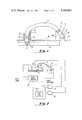
- FIG. 1is a perspective view of an ink jet system representing a preferred embodiment of the invention
- FIG. 2is a partially schematic diagram of the system of FIG. 1 in combination with control circuitry
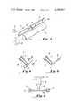
- FIG. 3is a perspective view of the system of FIG. 1 in a facsimile apparatus
- FIG. 4is an enlarged sectional view of a control electrode juxtaposed to an ink jet as shown in FIG. 2;
- FIG. 5is the enlarged view of FIG. 4 with the control electrode in another position
- FIG. 6is a view taken along line 6--6 of FIG. 4 illustrating one way in which the control electrode may be mounted so as to move between the position shown in FIG. 4 and the position shown in FIG. 5.
- the systemcomprises an ink jet 10 comprising an orifice 12 for projecting ink jet droplets from a substantially tubular chamber 14 surrounded at its periphery by a substantially tubular piezoelectric transducer 16.
- the transducer 16is driven by signals applied to conductive leads 18 and 20 connected respectively to the transducer 16, and the tubular chamber 14 so as to contract the volume within the chamber 14 depending upon the state of energization of the transducer 16.
- the jet 10is coupled to a novel piezoelectric pump 22 which is constructed in accordance with this invention.
- the pump 22which is relatively inexpensive and simple in construction also comprises an orifice 24 at the outlet of a tubular chamber 26 which is surrounded at its periphery by a piezoelectric transducer 28.
- the volume of the chamber 26contracts and expands so as to draw ink from an ink reservoir 30 up into the chamber 26 in response to the state of energization of the transducer 28 which is controlled by drive signals applied between the transducer 28 and the tubular chamber 26 by leads 37 and 32.
- the piezoelectric pump 22supplies ink from the reservoir 30 to the jet 10 through a tube or hose 34.
- the pump 22is energized for purposes of priming and/or purging the jet 10. Once priming or purging has been accomplished, the pump 22 may be de-energized by discontinuing the application of drive signals between the leads 30 and 32.
- the pump 22is shown in FIG. 1 as mounted within a sleeve 36 such that the orifice 24 is immersed below a supply of ink 38 within the reservoir 30.
- the jet 10is mounted on a support member 40. It will therefore be appreciated that both the jet 10 as well as the pump 22 are carried by the reservoir 30 so as to permit the pump 22 in its entirety to be disposable along with the remainder of the ink jet system including the reservoir 30 and the jet 10.
- the pump 22is very similar in construction to the ink jet 10.
- the orifice 24 of the pump 22has a maximum cross-sectional dimension of 1 to 6 mils. which is substantially the same as the maximum cross-sectional dimension of the orifice 12 of the jet 10.
- the structure of the jet 10may be further understood. It will also be understood that the jet structure disclosed therein is applicable to the pump 22. As a consequence, the jet 10 and the pump 22 may, under certain circumstances, be utilized almost interchangeably so as to minimize manufacturing problems in the assembly of the system. Moreover, the same drive impulses or signals may be utilized to drive the jet 10 as well as the pump 22. It will, of course, be appreciated that these drive signals will not be simultaneously applied to the jet 10 and the pump 22. It will also be appreciated that the orifice 24 in the pump 22 is sufficiently small so as to act as an in-line filter and prevent the accumulation of debris and the clogging of the orifice 12 of the jet 10.
- a sensing electrode 42is juxtaposed to the orifice 12 of the jet 10 for sensing the accumulation of ink at the orifice 12 indicating the primed or purged condition.
- a circuitis closed from the electrode 42 back through the ink within the hose 34 to the ink 38 within the reservoir 30. This will produce an output signal from the pump control circuitry 46 so as to inhibit an AND gate 48 thereby preventing drive signals from the pump drive circuit 50 from reaching the transducer 28.
- a prime start signalis applied to the pump control circuit 46.
- the same pump drive circuit 50is also coupled to the transducer 16 of the jet 10.
- the drive signals from the pump drive circuit 50are controlled by print commands applied to an AND gate 52 so as to be asynchronous with the priming or purging function.
- FIG. 3it will be readily seen that the system of FIG. 1 may be readily mounted on a moving head 54 of a facsimile apparatus which is juxtaposed to a rotating drum 56 adapted to carry copy medium so as to reproduce dark/light variations of a remotely located document.
- the drum 56is rotated in a direction indicated by an arrow 58 by means of a motor 60.
- the head 54moves in a direction indicated by an arrow 62 by means of a belt 64 which passes around a pair of pulleys 66 and 68 which are driven by a motor 70.
- the pump 22 as well as the jet 10may be removed with the reservoir 30. Referring to FIGS.
- the sensing electrode 42may be moved between a position juxtaposed to the orifice 12 as shown in FIG. 4 to a position clear of or spaced from the orifice 2 as shown in FIG. 5. With the sensing electrode 42 is in the position shown in FIG. 4, it is capable of sensing an accumulation of ink 38 at the orifice 12. Once that accumulation of ink has been sensed, the pump control circuit 46 shown in FIG. 2 terminates pumping by the pump 22, and the jet is primed and ready to begin a print cycle.
- the sensing electrode 42may be mounted so that it is juxtaposed to the jet when the jet is in the home or at rest position. Referring to FIG. 6, it will be seen that the sensing electrode 42 which may also act as a cover plate for the orifice 12 may be mounted in tracks 72 of support 74. It will, of course, be appreciated that other structures may be utilized to provide the sliding capability for the sensing electrode 42.
Landscapes
- Ink Jet (AREA)
Abstract
Description
Claims (12)
Priority Applications (1)
| Application Number | Priority Date | Filing Date | Title |
|---|---|---|---|
| US06/203,590US4389657A (en) | 1980-11-03 | 1980-11-03 | Ink jet system |
Applications Claiming Priority (1)
| Application Number | Priority Date | Filing Date | Title |
|---|---|---|---|
| US06/203,590US4389657A (en) | 1980-11-03 | 1980-11-03 | Ink jet system |
Publications (1)
| Publication Number | Publication Date |
|---|---|
| US4389657Atrue US4389657A (en) | 1983-06-21 |
Family
ID=22754590
Family Applications (1)
| Application Number | Title | Priority Date | Filing Date |
|---|---|---|---|
| US06/203,590Expired - LifetimeUS4389657A (en) | 1980-11-03 | 1980-11-03 | Ink jet system |
Country Status (1)
| Country | Link |
|---|---|
| US (1) | US4389657A (en) |
Cited By (14)
| Publication number | Priority date | Publication date | Assignee | Title |
|---|---|---|---|---|
| US4516134A (en)* | 1982-10-22 | 1985-05-07 | Fuji Xerox Co., Ltd. | Ink jet printer shut-down control |
| US4523199A (en)* | 1982-09-29 | 1985-06-11 | Exxon Research & Engineering Co. | High stability demand ink jet apparatus and method of operating same |
| US4555718A (en)* | 1983-01-25 | 1985-11-26 | Sharp Kabushiki Kaisha | Piezo activated pump in an ink liquid supply system |
| US4590482A (en)* | 1983-12-14 | 1986-05-20 | Hewlett-Packard Company | Nozzle test apparatus and method for thermal ink jet systems |
| US4658272A (en)* | 1981-10-02 | 1987-04-14 | Canon Kabushiki Kaisha | Ink-supplying device |
| DE3634034A1 (en)* | 1985-10-09 | 1987-04-16 | Seiko Epson Corp | INK DROP DETECTOR |
| US4933591A (en)* | 1988-01-06 | 1990-06-12 | Ford Aerospace Corporation | Double saggital pull stroke amplifier |
| US5182572A (en)* | 1981-12-17 | 1993-01-26 | Dataproducts Corporation | Demand ink jet utilizing a phase change ink and method of operating |
| US5239316A (en)* | 1989-11-09 | 1993-08-24 | Dataproducts Corporation | Head tend media and system for an ink jet printer |
| US5541624A (en)* | 1984-10-15 | 1996-07-30 | Dataproducts Corporation | Impulse ink jet apparatus employing ink in solid state form |
| US6007178A (en)* | 1996-08-23 | 1999-12-28 | Pitney Bowes Inc. | Drive gear system using a single motor for a priming operation and driving a platen in a postage meter |
| US6050679A (en)* | 1992-08-27 | 2000-04-18 | Hitachi Koki Imaging Solutions, Inc. | Ink jet printer transducer array with stacked or single flat plate element |
| US6530755B2 (en)* | 2000-04-07 | 2003-03-11 | Tecan Trading Ag | Micropump |
| US20070040872A1 (en)* | 2005-08-17 | 2007-02-22 | Samsung Electro-Mechanics Co., Ltd. | Inkjet head |
Citations (13)
| Publication number | Priority date | Publication date | Assignee | Title |
|---|---|---|---|---|
| US3215078A (en)* | 1964-08-31 | 1965-11-02 | Charles L Stec | Controlled volume piezoelectric pumps |
| US3683212A (en)* | 1970-09-09 | 1972-08-08 | Clevite Corp | Pulsed droplet ejecting system |
| US3828357A (en)* | 1973-03-14 | 1974-08-06 | Gould Inc | Pulsed droplet ejecting system |
| US3831727A (en)* | 1972-11-21 | 1974-08-27 | Ibm | Pressurizing system for ink jet printing apparatus |
| US4005435A (en)* | 1975-05-15 | 1977-01-25 | Burroughs Corporation | Liquid jet droplet generator |
| US4011474A (en)* | 1974-10-03 | 1977-03-08 | Pz Technology, Inc. | Piezoelectric stack insulation |
| US4032929A (en)* | 1975-10-28 | 1977-06-28 | Xerox Corporation | High density linear array ink jet assembly |
| US4045801A (en)* | 1975-06-03 | 1977-08-30 | Ricoh Company, Ltd. | Ink ejection head for printer |
| US4068144A (en)* | 1976-09-20 | 1978-01-10 | Recognition Equipment Incorporated | Liquid jet modulator with piezoelectric hemispheral transducer |
| US4115036A (en)* | 1976-03-01 | 1978-09-19 | U.S. Philips Corporation | Pump for pumping liquid in a pulse-free flow |
| US4149172A (en)* | 1974-12-20 | 1979-04-10 | Siemens Aktiengesellschaft | Ink supply system for piezoelectrically operated printing jets |
| US4241357A (en)* | 1979-09-24 | 1980-12-23 | Exxon Research & Engineering Co. | Method and apparatus for operating an ink jet |
| US4291316A (en)* | 1975-06-03 | 1981-09-22 | Ricoh Co., Ltd. | System for driving ink drop generator of ink-jet printer |
- 1980
- 1980-11-03USUS06/203,590patent/US4389657A/ennot_activeExpired - Lifetime
Patent Citations (13)
| Publication number | Priority date | Publication date | Assignee | Title |
|---|---|---|---|---|
| US3215078A (en)* | 1964-08-31 | 1965-11-02 | Charles L Stec | Controlled volume piezoelectric pumps |
| US3683212A (en)* | 1970-09-09 | 1972-08-08 | Clevite Corp | Pulsed droplet ejecting system |
| US3831727A (en)* | 1972-11-21 | 1974-08-27 | Ibm | Pressurizing system for ink jet printing apparatus |
| US3828357A (en)* | 1973-03-14 | 1974-08-06 | Gould Inc | Pulsed droplet ejecting system |
| US4011474A (en)* | 1974-10-03 | 1977-03-08 | Pz Technology, Inc. | Piezoelectric stack insulation |
| US4149172A (en)* | 1974-12-20 | 1979-04-10 | Siemens Aktiengesellschaft | Ink supply system for piezoelectrically operated printing jets |
| US4005435A (en)* | 1975-05-15 | 1977-01-25 | Burroughs Corporation | Liquid jet droplet generator |
| US4045801A (en)* | 1975-06-03 | 1977-08-30 | Ricoh Company, Ltd. | Ink ejection head for printer |
| US4291316A (en)* | 1975-06-03 | 1981-09-22 | Ricoh Co., Ltd. | System for driving ink drop generator of ink-jet printer |
| US4032929A (en)* | 1975-10-28 | 1977-06-28 | Xerox Corporation | High density linear array ink jet assembly |
| US4115036A (en)* | 1976-03-01 | 1978-09-19 | U.S. Philips Corporation | Pump for pumping liquid in a pulse-free flow |
| US4068144A (en)* | 1976-09-20 | 1978-01-10 | Recognition Equipment Incorporated | Liquid jet modulator with piezoelectric hemispheral transducer |
| US4241357A (en)* | 1979-09-24 | 1980-12-23 | Exxon Research & Engineering Co. | Method and apparatus for operating an ink jet |
Non-Patent Citations (2)
| Title |
|---|
| Description of U.S. Pat. No. 4,011,474; Physics International Co.; 4 pp.* |
| Piezomotors--Electromechanical Muscle; C. G. O'Neill, D. S. Randall, and P. C. Smiley; Copyright 1980, Soc. of Automotive Eng., Inc., pp. 1-11.* |
Cited By (14)
| Publication number | Priority date | Publication date | Assignee | Title |
|---|---|---|---|---|
| US4658272A (en)* | 1981-10-02 | 1987-04-14 | Canon Kabushiki Kaisha | Ink-supplying device |
| US5182572A (en)* | 1981-12-17 | 1993-01-26 | Dataproducts Corporation | Demand ink jet utilizing a phase change ink and method of operating |
| US4523199A (en)* | 1982-09-29 | 1985-06-11 | Exxon Research & Engineering Co. | High stability demand ink jet apparatus and method of operating same |
| US4516134A (en)* | 1982-10-22 | 1985-05-07 | Fuji Xerox Co., Ltd. | Ink jet printer shut-down control |
| US4555718A (en)* | 1983-01-25 | 1985-11-26 | Sharp Kabushiki Kaisha | Piezo activated pump in an ink liquid supply system |
| US4590482A (en)* | 1983-12-14 | 1986-05-20 | Hewlett-Packard Company | Nozzle test apparatus and method for thermal ink jet systems |
| US5541624A (en)* | 1984-10-15 | 1996-07-30 | Dataproducts Corporation | Impulse ink jet apparatus employing ink in solid state form |
| DE3634034A1 (en)* | 1985-10-09 | 1987-04-16 | Seiko Epson Corp | INK DROP DETECTOR |
| US4933591A (en)* | 1988-01-06 | 1990-06-12 | Ford Aerospace Corporation | Double saggital pull stroke amplifier |
| US5239316A (en)* | 1989-11-09 | 1993-08-24 | Dataproducts Corporation | Head tend media and system for an ink jet printer |
| US6050679A (en)* | 1992-08-27 | 2000-04-18 | Hitachi Koki Imaging Solutions, Inc. | Ink jet printer transducer array with stacked or single flat plate element |
| US6007178A (en)* | 1996-08-23 | 1999-12-28 | Pitney Bowes Inc. | Drive gear system using a single motor for a priming operation and driving a platen in a postage meter |
| US6530755B2 (en)* | 2000-04-07 | 2003-03-11 | Tecan Trading Ag | Micropump |
| US20070040872A1 (en)* | 2005-08-17 | 2007-02-22 | Samsung Electro-Mechanics Co., Ltd. | Inkjet head |
Similar Documents
| Publication | Publication Date | Title |
|---|---|---|
| US4389657A (en) | Ink jet system | |
| US3974508A (en) | Air purging system for a pulsed droplet ejecting system | |
| US4383264A (en) | Demand drop forming device with interacting transducer and orifice combination | |
| US5500657A (en) | Air-bubble detection apparatus of ink jet recording head, and method and apparatus for restoring ink jet recording head | |
| US4593291A (en) | Method for operating an ink jet device to obtain high resolution printing | |
| CN1756662B (en) | droplet ejection device | |
| US4095237A (en) | Ink jet printing head | |
| US6174038B1 (en) | Ink jet printer and drive method therefor | |
| US5912688A (en) | Spring bag based, off axis ink delivery system and pump trigger | |
| CA1267034A (en) | Hydraulic servomechanism for controlling the pressure of writing fluid in an ink jet printing system | |
| US4518974A (en) | Ink jet air removal system | |
| US6183058B1 (en) | Self-cleaning ink jet printer system with reverse fluid flow and method of assembling the printer system | |
| US3902083A (en) | Pulsed droplet ejecting system | |
| US6142601A (en) | Self-cleaning ink jet printer with reverse fluid flow and method of assembling the printer | |
| EP0110985A1 (en) | Ink jet printer. | |
| GB1337773A (en) | Pulsed droplet ejecting system | |
| US5757396A (en) | Ink jet printhead having an ultrasonic maintenance system incorporated therein and an associated method of maintaining an ink jet printhead by purging foreign matter therefrom | |
| JPS5932313B2 (en) | Method for cleaning ink passages in inkjet recording devices | |
| EP0002591B1 (en) | Priming means for liquid ink writing apparatus | |
| US6168256B1 (en) | Self-cleaning ink jet printer with oscillating septum and method of assembling the printer | |
| US8474945B2 (en) | Dislodging and removing bubbles from inkjet printhead | |
| US4980699A (en) | Liquid injection recording method for accurately producing an image regardless of ambient temperature | |
| CN1330496C (en) | Liquid injector with internal sliding rotary element type displacemont pump | |
| US5483266A (en) | Ink jet recording apparatus with two storage modes | |
| JPH0694014B2 (en) | Small high speed spray gun |
Legal Events
| Date | Code | Title | Description |
|---|---|---|---|
| AS | Assignment | Owner name:EXXON RESEARCH AND ENGINEERING COMPANY, A CORP. OF Free format text:ASSIGNMENT OF ASSIGNORS INTEREST.;ASSIGNOR:MC MAHON, JAMES;REEL/FRAME:004093/0184 Effective date:19800821 Owner name:EXXON RESEARCH AND ENGINEERING COMPANY, A CORP. OF Free format text:ASSIGNMENT OF ASSIGNORS INTEREST;ASSIGNOR:MC MAHON, JAMES;REEL/FRAME:004093/0184 Effective date:19800821 | |
| STCF | Information on status: patent grant | Free format text:PATENTED CASE | |
| AS | Assignment | Owner name:EXXON ENTERPRISES, A DIVISION OF EXXON CORPORATION Free format text:ASSIGNMENT OF ASSIGNORS INTEREST.;ASSIGNOR:EXXON RESEARCH AND ENGINEERING COMPANY A CORP. OF DE.;REEL/FRAME:004610/0085 Effective date:19850715 Owner name:EXXON ENTERPRISES, A DIVISION OF EXXON CORPORATION Free format text:ASSIGNMENT OF ASSIGNORS INTEREST;ASSIGNOR:EXXON RESEARCH AND ENGINEERING COMPANY A CORP. OF DE.;REEL/FRAME:004610/0085 Effective date:19850715 | |
| AS | Assignment | Owner name:EXXON PRINTING SYSTEMS, INC., A CORP. OF DE. Free format text:ASSIGNMENT OF ASSIGNORS INTEREST.;ASSIGNOR:EXXON ENTERPRISES, A DIVISION OF EXXON CORPORATION, A CORP. OF N.J.;REEL/FRAME:004592/0913 Effective date:19860715 | |
| AS | Assignment | Owner name:EXXON PRINTING SYSTEMS, INC., A CORP. OF DE. Free format text:ASSIGNMENT OF ASSIGNORS INTEREST.;ASSIGNOR:EXXON ENTERPRISES, A DIVISION OF EXXON CORPORATION, A CORP. OF NJ;REEL/FRAME:004621/0836 Effective date:19860715 Owner name:EXXON ENTERPRISES, A CORP OF NJ Free format text:ASSIGNMENT OF ASSIGNORS INTEREST.;ASSIGNOR:EXXON RESEARCH AND ENGINEERING COMPANY;REEL/FRAME:004621/0263 Effective date:19861008 | |
| AS | Assignment | Owner name:DATAPRODUCTS CORPORATION, A CORP. OF CA. Free format text:ASSIGNMENT OF ASSIGNORS INTEREST.;ASSIGNOR:IMAGING SOLUTIONS, INC;REEL/FRAME:004766/0581 Effective date:19870717 Owner name:RELIANCE PRINTING SYSTEMS, INC. Free format text:CHANGE OF NAME;ASSIGNOR:EXXON PRINTING SYSTEMS, INC.;REEL/FRAME:004767/0736 Effective date:19861229 Owner name:IMAGING SOLUTIONS, INC. Free format text:CHANGE OF NAME;ASSIGNOR:RELIANCE PRINTING SYSTEMS, INC.;REEL/FRAME:004804/0391 Effective date:19870128 Owner name:IMAGING SOLUTIONS, INC.,STATELESS Free format text:CHANGE OF NAME;ASSIGNOR:RELIANCE PRINTING SYSTEMS, INC.;REEL/FRAME:004804/0391 Effective date:19870128 | |
| AS | Assignment | Owner name:HOWTEK, INC., 21 PARK AVENUE, HUDSON, NEW HAMPSHIR Free format text:LICENSE;ASSIGNOR:DATAPRODUCTS CORPORATION, A DE CORP.;REEL/FRAME:004815/0431 Effective date:19871130 |