US4388736A - Tank flushing means - Google Patents
Tank flushing meansDownload PDFInfo
- Publication number
- US4388736A US4388736AUS06/270,368US27036881AUS4388736AUS 4388736 AUS4388736 AUS 4388736AUS 27036881 AUS27036881 AUS 27036881AUS 4388736 AUS4388736 AUS 4388736A
- Authority
- US
- United States
- Prior art keywords
- tank
- flush
- flushing
- rod
- flush valve
- Prior art date
- Legal status (The legal status is an assumption and is not a legal conclusion. Google has not performed a legal analysis and makes no representation as to the accuracy of the status listed.)
- Expired - Fee Related
Links
- 238000011010flushing procedureMethods0.000titleclaimsabstractdescription35
- 230000008878couplingEffects0.000claimsabstractdescription4
- 238000010168coupling processMethods0.000claimsabstractdescription4
- 238000005859coupling reactionMethods0.000claimsabstractdescription4
- 239000007788liquidSubstances0.000claims3
- XLYOFNOQVPJJNP-UHFFFAOYSA-NwaterSubstancesOXLYOFNOQVPJJNP-UHFFFAOYSA-N0.000description23
- 239000000463materialSubstances0.000description3
- XAGFODPZIPBFFR-UHFFFAOYSA-NaluminiumChemical compound[Al]XAGFODPZIPBFFR-UHFFFAOYSA-N0.000description2
- 229910052782aluminiumInorganic materials0.000description2
- 229910001369BrassInorganic materials0.000description1
- RYGMFSIKBFXOCR-UHFFFAOYSA-NCopperChemical compound[Cu]RYGMFSIKBFXOCR-UHFFFAOYSA-N0.000description1
- 229920006328StyrofoamPolymers0.000description1
- 230000005540biological transmissionEffects0.000description1
- 239000010951brassSubstances0.000description1
- 238000010276constructionMethods0.000description1
- 239000010949copperSubstances0.000description1
- 229910052802copperInorganic materials0.000description1
- 230000007797corrosionEffects0.000description1
- 238000005260corrosionMethods0.000description1
- 230000000977initiatory effectEffects0.000description1
- 238000009434installationMethods0.000description1
- 230000000630rising effectEffects0.000description1
- 239000008261styrofoamSubstances0.000description1
Images
Classifications
- E—FIXED CONSTRUCTIONS
- E03—WATER SUPPLY; SEWERAGE
- E03D—WATER-CLOSETS OR URINALS WITH FLUSHING DEVICES; FLUSHING VALVES THEREFOR
- E03D1/00—Water flushing devices with cisterns ; Setting up a range of flushing devices or water-closets; Combinations of several flushing devices
- E03D1/02—High-level flushing systems
- E03D1/14—Cisterns discharging variable quantities of water also cisterns with bell siphons in combination with flushing valves
- E03D1/142—Cisterns discharging variable quantities of water also cisterns with bell siphons in combination with flushing valves in cisterns with flushing valves
- E03D1/144—Cisterns discharging variable quantities of water also cisterns with bell siphons in combination with flushing valves in cisterns with flushing valves having a single flush outlet and an additional float for delaying the valve closure
- E—FIXED CONSTRUCTIONS
- E03—WATER SUPPLY; SEWERAGE
- E03D—WATER-CLOSETS OR URINALS WITH FLUSHING DEVICES; FLUSHING VALVES THEREFOR
- E03D1/00—Water flushing devices with cisterns ; Setting up a range of flushing devices or water-closets; Combinations of several flushing devices
- E03D1/30—Valves for high or low level cisterns; Their arrangement ; Flushing mechanisms in the cistern, optionally with provisions for a pre-or a post- flushing and for cutting off the flushing mechanism in case of leakage
- E03D1/304—Valves for high or low level cisterns; Their arrangement ; Flushing mechanisms in the cistern, optionally with provisions for a pre-or a post- flushing and for cutting off the flushing mechanism in case of leakage with valves with own buoyancy
- E03D1/306—Valves for high or low level cisterns; Their arrangement ; Flushing mechanisms in the cistern, optionally with provisions for a pre-or a post- flushing and for cutting off the flushing mechanism in case of leakage with valves with own buoyancy with articulated valves
- E—FIXED CONSTRUCTIONS
- E03—WATER SUPPLY; SEWERAGE
- E03D—WATER-CLOSETS OR URINALS WITH FLUSHING DEVICES; FLUSHING VALVES THEREFOR
- E03D1/00—Water flushing devices with cisterns ; Setting up a range of flushing devices or water-closets; Combinations of several flushing devices
- E03D1/02—High-level flushing systems
- E03D1/14—Cisterns discharging variable quantities of water also cisterns with bell siphons in combination with flushing valves
- E03D2001/147—Cisterns discharging variable quantities of water also cisterns with bell siphons in combination with flushing valves having provisions for active interruption of flushing
Definitions
- the present inventionrelates to an improved flushing apparatus for a flush tank used for toilet bowls and the like.
- itprovides an improved means for reducing the amount of flushing water utilized by permitting the flushing action to be terminated under the control of the operator.
- the improved flushing apparatus of the present inventionis for use in the tank type toilet flushing means now widely used.
- flushing devicesutilize a storage tank and handle control means for initiating the flushing action. This is normally done by operating a flushing valve so that the system goes through one complete flushing cycle where the flushing tank is completely emptied during the cycle and is then automatically refilled.
- the present inventionprovides means for terminating the outflow of the water from the flushing tank under the control of the operator to permit an effective flush utilizing only a portion of the tank water.
- an object of the present inventionis to provide an improved apparatus for a controlled toilet flush wherin the operator may adjustably control the amount of water utilized.
- Another object of the present inventionis to provide an improved apparatus for a controlled toilet flush wherein the operator may adjustably control the amount of water utilized.
- Another object of the present inventionis to provide an improved flushing apparatus for a toilet or the like.
- Another object of the present inventionis provide an improved tank type toilet apparatus.
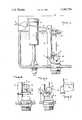
- FIG. 1is a front elevational view of a preferred embodiment of the flushing apparatus in accordance with the present invention.
- FIG. 2is an enlarged fragmentary perspective view of the flush control rod in accordance with the present invention.
- FIG. 3 and 4are enlarged elevational views of the flushing apparatus in accordance with the invention in its open and closed position respectively.
- the apparatus of the present inventionis for use with a conventional tank type toilet flushing system including a tank 1 with a water inlet valve 2 and a handle controlled flushing valve.
- the tankis filled through the inlet valve 2 which is coupled to a source of water under pressure.
- the water inlet to the tank 1includes the inlet valve 2 controlled by a float 4.
- Such an inlet valveis illustrated, for example, in U.S. Pat. No. 3,982,566 dated Sept. 28, 1976.
- the inlet valve 2is controlled by the level of water 5 in the flush tank 1. Whenever the water falls below a predetermined level, as during a flushing cycle, the inlet valve 2 opens to admit tank refilling water.
- the float 4is lifted by the water level to shut off the incoming water supply at a predetermined water level.
- the inlet valveforms no portion of the present invention.
- the flushing operationis performed by the flush valve 3 which is opened to initiate the flushing action and which automatically recloses at the end of the flushing cycle.
- the flushing valveis opened by a flushing handle and the tank is emptied at which point the flushing valve drops closed and thereafter remains closed for the above described refilling action.
- the improved flushing apparatus of the present inventionincludes means for terminating the flow of the water 5 from the tank 1 at any time after the flush has been started and at the control of the operator. This permits the flushing action to be stopped while the tank remains partially full of water thereby conserving water.
- the flushing apparatusincludes a flapper type valve 6 pivotally mounted at 7 on the tank 1 or the overflow tube 8 or otherwise so that it may be moved from the close position as illustrated in FIG. 4 to an open position as illustrated in FIG. 3 under the control of a flush handle 9.
- the pivotally mounted flush handle 9has an interconnected flush lever 10.
- the lever 10is rotated in a counter clockwise direction (FIG. 1) so that its free or right hand end is raised within the tank 1 lifting the interconnected flush control rod 11 and the flapper valve 6 connected to the lower end of the flush control rod 11.
- the flush valve 6Under normal conditions and in the absense of further movement of the flush handle 9, the flush valve 6 will remain open until the flush water 5 in the tank 1 has drained out of the tank 1 at which point the flapper valve 6 and the interconnected flush rod 11 drop down to the closed position.
- the rising water admitted through the inlet valve 2flows over and around the flapper valve 6 so that made the water pressure keeps the flush valve 3 closed.
- the flow control rod 11is made of relatively stiff material such as a copper or aluminum rod material permitting force to be transmitted by it from the control lever 10 to the flapper valve 6. In order to terminate the flow of water from the tank at any point during the flushing action, it is only necessary to turn the flush handle 9 in a clockwise direction thereby forcing the control lever 10 and the interconnected flush rod 11 downwardly and back to the closed position.
- the flush control rod 11is preferably made of a corrosion resistant material of suitable stiffness for the above described closing action.
- An aluminum rod with a diameter of about 3/32 of an inch or a generally similar brass rodis suitable for this purpose.
- an S-shaped bend 12is provided in the rod. Such a bend does not interfere with the transmission of sufficient force during the above described valve closing operation but at the same time permits a rod adjustment during installation.
- a Styrofoam or other float 12is preferably provided on the control rod 11. It is conveniently mounted by being frictionally inserted within a C-shaped section 16 of the control rod 11 as illustrated in FIGS. 2 through 4. The lower end of the rod 11 is conveniently attached to a provided at the bottom of the flush control rod 11.
- the hook 15may be inserted into the flapper valve eye 14 before the top of the flush control rod 13 is pressed into position on the control rod 11 so that it is firmly mounted thereon and so that it closes the top of the flapper valve coupling hook 15.
Landscapes
- Health & Medical Sciences (AREA)
- Life Sciences & Earth Sciences (AREA)
- Engineering & Computer Science (AREA)
- Hydrology & Water Resources (AREA)
- Public Health (AREA)
- Water Supply & Treatment (AREA)
- Sanitary Device For Flush Toilet (AREA)
Abstract
Description
Claims (2)
Priority Applications (1)
| Application Number | Priority Date | Filing Date | Title |
|---|---|---|---|
| US06/270,368US4388736A (en) | 1981-06-04 | 1981-06-04 | Tank flushing means |
Applications Claiming Priority (1)
| Application Number | Priority Date | Filing Date | Title |
|---|---|---|---|
| US06/270,368US4388736A (en) | 1981-06-04 | 1981-06-04 | Tank flushing means |
Publications (1)
| Publication Number | Publication Date |
|---|---|
| US4388736Atrue US4388736A (en) | 1983-06-21 |
Family
ID=23031065
Family Applications (1)
| Application Number | Title | Priority Date | Filing Date |
|---|---|---|---|
| US06/270,368Expired - Fee RelatedUS4388736A (en) | 1981-06-04 | 1981-06-04 | Tank flushing means |
Country Status (1)
| Country | Link |
|---|---|
| US (1) | US4388736A (en) |
Cited By (6)
| Publication number | Priority date | Publication date | Assignee | Title |
|---|---|---|---|---|
| US4536900A (en)* | 1984-05-21 | 1985-08-27 | Hayes Garrett P | Water conserving flush valve for toilets |
| US4937894A (en)* | 1989-08-17 | 1990-07-03 | Hill Jr Russell L | Dual flush toilet |
| US5237711A (en)* | 1991-04-29 | 1993-08-24 | Mortensen La Vaughn L | Multiple flush toilet valve assembly |
| US20050251164A1 (en)* | 1995-02-24 | 2005-11-10 | Gifford Hanson S Iii | Devices and methods for performing avascular anastomosis |
| US20090126094A1 (en)* | 2007-11-19 | 2009-05-21 | Laube Stephen G | User-controlled water saving toilet |
| US8397319B1 (en) | 2011-02-17 | 2013-03-19 | Michael Peter Senderak | Add-on flush control mechanism to provide water conservation |
Citations (5)
| Publication number | Priority date | Publication date | Assignee | Title |
|---|---|---|---|---|
| US2908914A (en)* | 1956-12-20 | 1959-10-20 | Edmund S Lasecki | Flush and stop rod for toilet tank |
| US3992728A (en)* | 1975-10-28 | 1976-11-23 | Jay Walter M | Water saving toilet device |
| US4183107A (en)* | 1978-07-24 | 1980-01-15 | Hare Nicholas S | Variable flush toilet valve mechanism |
| US4184215A (en)* | 1978-06-19 | 1980-01-22 | Birdsall Leo S | Toilet flushing apparatus |
| CA1080902A (en)* | 1977-05-27 | 1980-07-08 | Peter V. Roosa | Flushing means |
- 1981
- 1981-06-04USUS06/270,368patent/US4388736A/ennot_activeExpired - Fee Related
Patent Citations (5)
| Publication number | Priority date | Publication date | Assignee | Title |
|---|---|---|---|---|
| US2908914A (en)* | 1956-12-20 | 1959-10-20 | Edmund S Lasecki | Flush and stop rod for toilet tank |
| US3992728A (en)* | 1975-10-28 | 1976-11-23 | Jay Walter M | Water saving toilet device |
| CA1080902A (en)* | 1977-05-27 | 1980-07-08 | Peter V. Roosa | Flushing means |
| US4184215A (en)* | 1978-06-19 | 1980-01-22 | Birdsall Leo S | Toilet flushing apparatus |
| US4183107A (en)* | 1978-07-24 | 1980-01-15 | Hare Nicholas S | Variable flush toilet valve mechanism |
Cited By (6)
| Publication number | Priority date | Publication date | Assignee | Title |
|---|---|---|---|---|
| US4536900A (en)* | 1984-05-21 | 1985-08-27 | Hayes Garrett P | Water conserving flush valve for toilets |
| US4937894A (en)* | 1989-08-17 | 1990-07-03 | Hill Jr Russell L | Dual flush toilet |
| US5237711A (en)* | 1991-04-29 | 1993-08-24 | Mortensen La Vaughn L | Multiple flush toilet valve assembly |
| US20050251164A1 (en)* | 1995-02-24 | 2005-11-10 | Gifford Hanson S Iii | Devices and methods for performing avascular anastomosis |
| US20090126094A1 (en)* | 2007-11-19 | 2009-05-21 | Laube Stephen G | User-controlled water saving toilet |
| US8397319B1 (en) | 2011-02-17 | 2013-03-19 | Michael Peter Senderak | Add-on flush control mechanism to provide water conservation |
Similar Documents
| Publication | Publication Date | Title |
|---|---|---|
| US4000526A (en) | Toilet flushing apparatus | |
| US4122564A (en) | Dual discharge valve unit | |
| US4080669A (en) | Two-level toilet flush system | |
| US3775778A (en) | Toilet flush tank mechanism | |
| US4145774A (en) | Dual flush apparatus for water closets | |
| US4351071A (en) | Water-saving device | |
| US3156930A (en) | Water saver for flush tank toilets | |
| US3095577A (en) | Toilet tank flushing mechanism | |
| US3908203A (en) | Toilet flush system | |
| US4388736A (en) | Tank flushing means | |
| US2754521A (en) | Toilet flush tank | |
| US4318194A (en) | Water closet diverter valve | |
| US2841169A (en) | Valve means | |
| US5129110A (en) | Selectable toilet-water-level flushing system | |
| US3945056A (en) | Dual flush toilets | |
| US5117514A (en) | Improved toilet-tank flapper valve | |
| US2645780A (en) | Water saving flush tank | |
| US4868933A (en) | Flush control devices | |
| US3296630A (en) | Toilet tank flushing mechanism | |
| US5442820A (en) | Toilet tank flushing mechanism | |
| US3982556A (en) | Tank flushing means | |
| US3385317A (en) | Zeta-adapter for water closets | |
| US2746060A (en) | Valve control means | |
| US2655665A (en) | Flush control device for water tanks | |
| US4017914A (en) | Water closet metering device |
Legal Events
| Date | Code | Title | Description |
|---|---|---|---|
| FEPP | Fee payment procedure | Free format text:MAINTENANCE FEE REMINDER MAILED (ORIGINAL EVENT CODE: REM.); ENTITY STATUS OF PATENT OWNER: LARGE ENTITY | |
| FEPP | Fee payment procedure | Free format text:SURCHARGE FOR LATE PAYMENT, PL 96-517 (ORIGINAL EVENT CODE: M176); ENTITY STATUS OF PATENT OWNER: LARGE ENTITY | |
| MAFP | Maintenance fee payment | Free format text:PAYMENT OF MAINTENANCE FEE, 4TH YEAR, PL 96-517 (ORIGINAL EVENT CODE: M170); ENTITY STATUS OF PATENT OWNER: LARGE ENTITY Year of fee payment:4 | |
| AS | Assignment | Owner name:HARP, ELWYN V., CONNECTICUT Free format text:ASSIGNS TO EACH ASSIGNEE A ONE-HALF INTEREST.;ASSIGNOR:ROOSA, VERNON D.;REEL/FRAME:005073/0408 Effective date:19890516 | |
| MAFP | Maintenance fee payment | Free format text:PAYMENT OF MAINTENANCE FEE, 8TH YEAR, PL 96-517 (ORIGINAL EVENT CODE: M171); ENTITY STATUS OF PATENT OWNER: LARGE ENTITY Year of fee payment:8 | |
| FEPP | Fee payment procedure | Free format text:PAYOR NUMBER ASSIGNED (ORIGINAL EVENT CODE: ASPN); ENTITY STATUS OF PATENT OWNER: LARGE ENTITY | |
| FEPP | Fee payment procedure | Free format text:MAINTENANCE FEE REMINDER MAILED (ORIGINAL EVENT CODE: REM.); ENTITY STATUS OF PATENT OWNER: LARGE ENTITY | |
| LAPS | Lapse for failure to pay maintenance fees | ||
| FP | Lapsed due to failure to pay maintenance fee | Effective date:19950621 | |
| STCH | Information on status: patent discontinuation | Free format text:PATENT EXPIRED DUE TO NONPAYMENT OF MAINTENANCE FEES UNDER 37 CFR 1.362 |