US4388091A - Air cleaner having a dust dumping valve - Google Patents
Air cleaner having a dust dumping valveDownload PDFInfo
- Publication number
- US4388091A US4388091AUS06/287,888US28788881AUS4388091AUS 4388091 AUS4388091 AUS 4388091AUS 28788881 AUS28788881 AUS 28788881AUS 4388091 AUS4388091 AUS 4388091A
- Authority
- US
- United States
- Prior art keywords
- housing
- dust
- air
- disposed
- engine
- Prior art date
- Legal status (The legal status is an assumption and is not a legal conclusion. Google has not performed a legal analysis and makes no representation as to the accuracy of the status listed.)
- Expired - Lifetime
Links
- 239000000428dustSubstances0.000titleclaimsabstractdescription61
- 239000002245particleSubstances0.000claimsabstractdescription16
- 238000002485combustion reactionMethods0.000claimsabstractdescription7
- 238000001914filtrationMethods0.000claimsdescription11
- 230000002093peripheral effectEffects0.000claimsdescription6
- 238000004140cleaningMethods0.000claims1
- 238000010276constructionMethods0.000description4
- 239000000463materialSubstances0.000description3
- 239000002184metalSubstances0.000description2
- 239000007787solidSubstances0.000description2
- 230000000712assemblyEffects0.000description1
- 238000000429assemblyMethods0.000description1
- 230000007423decreaseEffects0.000description1
- 230000006866deteriorationEffects0.000description1
- 230000000694effectsEffects0.000description1
- 238000009434installationMethods0.000description1
- 230000002028prematureEffects0.000description1
- 230000010349pulsationEffects0.000description1
Images

Classifications
- B—PERFORMING OPERATIONS; TRANSPORTING
- B01—PHYSICAL OR CHEMICAL PROCESSES OR APPARATUS IN GENERAL
- B01D—SEPARATION
- B01D46/00—Filters or filtering processes specially modified for separating dispersed particles from gases or vapours
- B01D46/24—Particle separators, e.g. dust precipitators, using rigid hollow filter bodies
- B01D46/2403—Particle separators, e.g. dust precipitators, using rigid hollow filter bodies characterised by the physical shape or structure of the filtering element
- B01D46/2411—Filter cartridges
- B—PERFORMING OPERATIONS; TRANSPORTING
- B01—PHYSICAL OR CHEMICAL PROCESSES OR APPARATUS IN GENERAL
- B01D—SEPARATION
- B01D46/00—Filters or filtering processes specially modified for separating dispersed particles from gases or vapours
- B01D46/42—Auxiliary equipment or operation thereof
- B01D46/48—Removing dust other than cleaning filters, e.g. by using collecting trays
- B—PERFORMING OPERATIONS; TRANSPORTING
- B01—PHYSICAL OR CHEMICAL PROCESSES OR APPARATUS IN GENERAL
- B01D—SEPARATION
- B01D50/00—Combinations of methods or devices for separating particles from gases or vapours
- B01D50/20—Combinations of devices covered by groups B01D45/00 and B01D46/00
- F—MECHANICAL ENGINEERING; LIGHTING; HEATING; WEAPONS; BLASTING
- F02—COMBUSTION ENGINES; HOT-GAS OR COMBUSTION-PRODUCT ENGINE PLANTS
- F02M—SUPPLYING COMBUSTION ENGINES IN GENERAL WITH COMBUSTIBLE MIXTURES OR CONSTITUENTS THEREOF
- F02M35/00—Combustion-air cleaners, air intakes, intake silencers, or induction systems specially adapted for, or arranged on, internal-combustion engines
- F02M35/02—Air cleaners
- F02M35/08—Air cleaners with means for removing dust, particles or liquids from cleaners; with means for indicating clogging; with by-pass means; Regeneration of cleaners
- F02M35/084—Dust collection chambers or discharge sockets, e.g. chambers fed by gravity or closed by a valve
Definitions
- Air cleanersare normally used with internal combustion engines in off-road equipment, such as tractors, bulldozers and the like, to filter the air before it is drawn into the engine.
- off-road equipmentsuch as tractors, bulldozers and the like
- the air being drawn to the enginecan contain substantial quantities of solid particles or dust, and it is desirable to separate the larger size dust particles from the air before the air is passed through the filter in the air cleaner in order to prevent premature clogging of the filter.
- U.S. Pat. Nos. 3,319,404 and 3,429,108show air cleaner constructions in which the air being drawn into the cleaner is initially swirled outwardly against the inner surface of the cleaner housing which serves to separate the larger solid particles or dust from the air stream. The air then flows through a central filter to the engine, while the separated particles are passed through an outlet tube in the lower end of the housing and are collected in a flexible rubber-like dust-dumping valve.
- valvesas disclosed in the aforementioned patents, are designed to collect and intermittently dump the dust.
- the valvesare constructed with an upper generally cylindrical portion, which acts as a trap to collect the dust, and the cylindrical portion terminates in a pair of lower lips which seal together under the influence of the engine vacuum.
- valves of this typeWith valves of this type, the weight of the dust collected in the trap, along with the engine vibration will intermittently cause the lips to open to dump or discharge a portion of the dust in the trap. On termination of engine operation, the weight of the dust will cause the lips to open to discharge the entire quantity of collected dust from the trap.
- the lip-type dumping valves as used in the pasthave certain disadvantages. As the valves are normally installed in an exposed location, and as they are formed out of flexible rubber-like material, they are frequently subjected to damage. In addition, the continual exposure to weather can cause rapid deterioration of the rubber-like material.
- the inventionrelates to an improved air cleaner for an internal combustion engine having a dust collecting and dumping mechanism.
- a transverse wallis spaced from an end wall of the air cleaner housing and divides the housing into a main filter chamber and an end chamber.
- the upper peripheral edge of the transverse wallhas a cut-out or notch which provides communication between the two chambers.
- the lower end of the housingis provided with a generally conical outlet that straddles the transverse wall and the lower small diameter end of the outlet communicates with an enlarged diameter container or trap.
- a flexible pressure responsive valvewhich can take the form of a flexible rubber-like disc that is mounted flatwise against the bottom surface of the trap and encloses a plurality of openings in the bottom surface. During normal operation of the engine, the disc will be drawn tightly against the openings to seal the same.
- the air being drawn to the cleanerwill be swirled outwardly and the heavier dust particles will pass through the notch in the transverse wall into the end chamber and then through the conical outlet to the trap.
- Other dust particles having lesser inertiawill be swirled against the inner surface of the transverse wall and can drop into the conical outlet for collection in the trap.
- the weight of the dust collected in the trap, along with the engine vibrationwill intermittently cause the rubber-like disc valve to open, to thereby discharge a portion of the dust from the trap.
- the weight of the dust in the trapwill open the disc-like valve to discharge the entire quantity of dust.
- the construction of the inventionhas distinct advantages over air cleaners as used in the past.
- the dumping valve of the inventionprovides a positive seal during periods of engine operation.
- the engine vacuumwill draw the rubber-like disc flatwise against the lower surface of the trap to completely close off the openings and prevent the entrance of air into the air cleaner. This greatly improves the air cleaner efficiency.
- the conical outletprovides a relatively large dust collecting opening communicating with both the main filtering chamber and the end chamber, which aids in the collection of dust, while the lower, small diameter end of the conical outlet functions to prevent the dust within the trap from being drawn back into the air cleaner by virtue of the engine vacuum.
- the air cleaner of the inventioncan also be readily adapted to aspirating muffler systems by merely connecting the lower end of the trap to the aspirating tube of the muffler.
- the disc-like valveserves a second function and operates as a check valve to prevent back flow through the air cleaner.
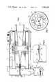
- FIG. 1is a vertical section of an air cleaner constructed in accordance with the invention
- FIG. 2is a section taken along line 2--2 of FIG. 1;
- FIG. 3is a section taken along line 3--3 of FIG. 1;
- FIG. 4is a section taken along line 4--4 of FIG. 1;
- FIG. 5is an enlarged fragmentary vertical section showing the dust dumping valve.
- the drawingsillustrate an air cleaner for an internal combustion engine as used in off-road equipment, such as tractors, road graders, bulldozers, and the like.
- the air cleanerincludes an outer cylindrical casing 1 which is mounted horizontally and one end of the casing is enclosed by head 2 while the opposite end of the casing is enclosed by a cup-shaped head 3.
- a filter assembly 4which is composed of an outer perforated metal sleeve 5, an inner perforated metal sleeve 6 and an intermediate layer of fibrous filtering material 7.
- One end of the filter assembly 4is connected to end member 8, while the opposite end of the filter assembly is secured to end ring 9 which is spaced from the head 2 by an annular resilient gasket 10.
- An outlet tube 11is secured within an opening in the head 2 and a plurality of braces 12 are connected to the outlet tube and extend within the open center of the filter assembly 4.
- the converging ends of braces 12are attached to the head of stud 13 which extends through aligned openings in the end member 8, the inner wall 14, and head 3.
- a cap 15is threaded onto the outer end of the stud 13, while a wing nut 16 is threaded on the central portion of the stud and bears against the end member 8.
- the edge of the wall 14is cut away to provide a notch 17 which provides communication between the interior of the casing 1 and the chamber 18 defined by head 3 and wall 14.
- Airis drawn into the casing 1 through an inlet tube 19 which extends through an opening in the upper portion of the casing 1, and the incoming air passes into the annular chamber defined by the casing 1 and annular wall 20.
- the airthen flows through a series of louvers 21 which causes the air to swirl outwardly against the inner surface of the casing 1.
- the heavier dust particles in the airare thrown outwardly against the casing wall and pass through the notch 17 into the chamber 18, while the air containing the lighter particles passes radially inwardly through the filter assembly 4 and is discharged from the outlet 11 to the engine.
- a dust collecting and dumping assemblycommunicates with the lower end of the chamber 18, and the assembly includes a generally conical outlet 22 having a large diameter upper end which connects with chamber 18 and a small diameter lower end which is secured within an opening in the upper surface of a cup-shaped trap or container 23.
- the lower end of the trap 23is closed off by a flanged plate 24, and the plate is provided with a plurality of openings or holes 25 which are arranged in a generally circular pattern about the central axis of the plate.
- a flexible rubber-like disc or valve 26which seals the openings 25.
- the disc valve 26is mounted on the plate 25 by means of a washer 27 and screw 28.
- the valve of the inventionprovides for intermittent discharge of the collected dust during engine operation and complete discharge of the accumulated dust on termination of engine operation.
- the valve 26is adapted to seal flatwise against the lower surface of plate 24, completely closing off the openings and thus preventing the entrance of atmospheric air into the trap. By preventing the entry of air into the trap, the efficiency of the air cleaner is improved.
- the air cleaner of the inventioncan be adapted to aspirating muffler systems by connecting a hose between the lower end of the trap 23 and the aspirating tube of the muffler.
- the aspirating effectduring engine operation, will continuously hold the rubber valve 26 in the open position, but the valve will function as a check valve to prevent reverse flow through the trap 23 in the event of back flow or back fire of the engine.
- the dust dumping valve assembly of the inventioncan be used with various types and configurations of air cleaners. As illustrated in the drawings, a single filter assembly 4 is utilized, but in other installations, multiple filter assemblies can be used. It is also contemplated that in certain air cleaners, the filter assembly can extend to a position adjacent the head 3, and in such cases, the internal wall 14 would be eliminated.
Landscapes
- Chemical & Material Sciences (AREA)
- Chemical Kinetics & Catalysis (AREA)
- Engineering & Computer Science (AREA)
- Physics & Mathematics (AREA)
- Geometry (AREA)
- Combustion & Propulsion (AREA)
- Mechanical Engineering (AREA)
- General Engineering & Computer Science (AREA)
- Filtering Of Dispersed Particles In Gases (AREA)
Abstract
Description
Claims (9)
Priority Applications (2)
| Application Number | Priority Date | Filing Date | Title |
|---|---|---|---|
| US06/287,888US4388091A (en) | 1981-07-29 | 1981-07-29 | Air cleaner having a dust dumping valve |
| CA000407238ACA1182402A (en) | 1981-07-29 | 1982-07-14 | Air cleaner having a dust dumping valve |
Applications Claiming Priority (1)
| Application Number | Priority Date | Filing Date | Title |
|---|---|---|---|
| US06/287,888US4388091A (en) | 1981-07-29 | 1981-07-29 | Air cleaner having a dust dumping valve |
Publications (1)
| Publication Number | Publication Date |
|---|---|
| US4388091Atrue US4388091A (en) | 1983-06-14 |
Family
ID=23104808
Family Applications (1)
| Application Number | Title | Priority Date | Filing Date |
|---|---|---|---|
| US06/287,888Expired - LifetimeUS4388091A (en) | 1981-07-29 | 1981-07-29 | Air cleaner having a dust dumping valve |
Country Status (2)
| Country | Link |
|---|---|
| US (1) | US4388091A (en) |
| CA (1) | CA1182402A (en) |
Cited By (35)
| Publication number | Priority date | Publication date | Assignee | Title |
|---|---|---|---|---|
| US4482368A (en)* | 1983-02-28 | 1984-11-13 | Nelson Industries, Inc. | Air cleaning assembly including a fastening assembly having a novel wing nut construction |
| US4555333A (en)* | 1984-02-09 | 1985-11-26 | Laval Claude C | Self-purging separator |
| US4661129A (en)* | 1984-05-30 | 1987-04-28 | Ab Ph. Nederman & Company | Filter cleaning device |
| US4697668A (en)* | 1986-01-13 | 1987-10-06 | Nelson Industries Inc. | Aspirating muffler |
| US4735640A (en)* | 1987-06-08 | 1988-04-05 | General Motors Corporation | Air cleaner liquid drain and filter assembly |
| US4885817A (en)* | 1986-09-09 | 1989-12-12 | Howa Machinery, Ltd. | Air-dust separation system for a pneumatic road-cleaning vehicle |
| US5059222A (en)* | 1990-09-25 | 1991-10-22 | Smith Daniel R | Engine air precleaner |
| EP0859145A1 (en)* | 1997-01-23 | 1998-08-19 | Denso Corporation | Air cleaner for internal combustion engine |
| WO2001096730A1 (en)* | 2000-06-13 | 2001-12-20 | Siemens Vdo Automotive Inc. | Integrated active noise control with self-cleaning filter apparatus |
| US20020189214A1 (en)* | 2001-06-13 | 2002-12-19 | Heinz Hettmann | Intake arrangement for combustion air |
| US6605131B2 (en) | 2000-06-13 | 2003-08-12 | Siemens Vdo Automotive Inc. | Integrated active noise control with self-cleaning filter apparatus |
| US20050284802A1 (en)* | 2004-06-23 | 2005-12-29 | Jankuski George A | Filtering device with integral filter status indicator |
| US7004987B2 (en) | 2002-03-28 | 2006-02-28 | Case Corporation | Intake air pre-cleaner with aspirator port chamber for collecting and holding particles for later aspiration |
| US20070006827A1 (en)* | 2005-07-11 | 2007-01-11 | Chaney Mark M | Sump for cooling package air intake housing of an agricultural machine |
| US20070079794A1 (en)* | 2005-10-12 | 2007-04-12 | Rotter Terrence M | Air cleaner assembly |
| WO2009117579A1 (en)* | 2008-03-20 | 2009-09-24 | Donaldson Company, Inc. | Pulse jet air cleaner with evacuation valve for dust and method to produce same |
| US20090308250A1 (en)* | 2008-06-13 | 2009-12-17 | Rotter Terrence M | Cyclonic Air Cleaner |
| US20100005764A1 (en)* | 2006-09-26 | 2010-01-14 | Aisan Kogyo Kabushiki Kaisha | Dust filter |
| WO2010104616A1 (en)* | 2009-03-12 | 2010-09-16 | Cummins Filtration Ip, Inc. | Inertially activated ejection valve |
| US20110012043A1 (en)* | 2009-07-15 | 2011-01-20 | Mann+Hummel Gmbh | Self actuating rotary dust valve |
| USD632770S1 (en) | 2008-06-13 | 2011-02-15 | Kohler Co. | Cyclonic air cleaner housing |
| US8404021B2 (en) | 2006-06-19 | 2013-03-26 | Donaldson Company, Inc. | Pulse jet air cleaner system; components; and, methods |
| CN103629020A (en)* | 2013-11-29 | 2014-03-12 | 长城汽车股份有限公司 | Vertical air filter |
| DE10316652B4 (en)* | 2003-04-11 | 2015-08-06 | Volkswagen Ag | Air filter for an internal combustion engine |
| US9186612B2 (en) | 2010-01-22 | 2015-11-17 | Donaldson Company, Inc. | Pulse jet air cleaner systems; evacuation valve arrangements; air cleaner components; and, methods |
| US20150343361A1 (en)* | 2013-01-14 | 2015-12-03 | Cummins Filtration Ip, Inc. | Cleanable Filter |
| WO2016113092A1 (en)* | 2015-01-15 | 2016-07-21 | Mahle Metal Leve S/A | Contaminant ejection valve |
| WO2016113093A1 (en)* | 2015-01-15 | 2016-07-21 | Mahle Metal Leve S/A | Contaminant ejection valve |
| KR20180070986A (en)* | 2016-12-19 | 2018-06-27 | 말레동현필터시스템 주식회사 | Air cleaner |
| CN108301946A (en)* | 2018-01-29 | 2018-07-20 | 金相律 | A kind of cyclone air cleaner |
| DE102018000544A1 (en) | 2018-01-24 | 2019-07-25 | Mann+Hummel Gmbh | Filter device, in particular for gas filtration |
| US20200155994A1 (en)* | 2019-01-28 | 2020-05-21 | Zhejiang Haanyo Intelligence Technology Co., Ltd | Self-cleaning air filter and control system thereof |
| WO2021025847A1 (en)* | 2019-08-07 | 2021-02-11 | Caterpillar Inc. | Actuated air filter dust valve |
| US20210299601A1 (en)* | 2020-03-24 | 2021-09-30 | Mann+Hummel Gmbh | Particle Discharge Device, Filter Assembly, and Method |
| CN114412676A (en)* | 2022-02-10 | 2022-04-29 | 石家庄欧亚惠通滤清器有限公司 | Automatic ash-discharging filter |
Families Citing this family (1)
| Publication number | Priority date | Publication date | Assignee | Title |
|---|---|---|---|---|
| DE4240048C2 (en)* | 1992-11-28 | 2002-11-07 | Mahle Filtersysteme Gmbh | Dust discharge valve |
Citations (10)
| Publication number | Priority date | Publication date | Assignee | Title |
|---|---|---|---|---|
| FR1361437A (en)* | 1963-04-08 | 1964-05-22 | S I A G A | Improvements to devices separating a solid or liquid phase from a gas carrier phase by centrifugation and linear acceleration of a mixture of the two phases |
| US3268018A (en)* | 1963-10-14 | 1966-08-23 | Smith Tool Co | Air or gas circulation rock bit anticontamination valve |
| US3633613A (en)* | 1970-04-17 | 1972-01-11 | Bendix Corp | Pressure relief means for a check valve |
| US3672130A (en)* | 1970-04-02 | 1972-06-27 | Donaldson Co Inc | Retention means for air cleaner element |
| US3796026A (en)* | 1971-04-05 | 1974-03-12 | Farr Co | Liquid-gas separator |
| US3816982A (en)* | 1972-12-13 | 1974-06-18 | Int Harvester Co | Automatic dust unloading valve in a centrifugal air cleaner |
| GB1378936A (en)* | 1972-02-22 | 1974-12-27 | Burgess Products Co Ltd | Dry-type air filters |
| US4127396A (en)* | 1977-07-28 | 1978-11-28 | Halle Industries, Inc. | Air pre-cleaner |
| US4155359A (en)* | 1977-05-23 | 1979-05-22 | Antoni Zagorski | Air filtering mask |
| US4261710A (en)* | 1979-03-16 | 1981-04-14 | Donaldson Company, Inc. | Two-stage air cleaner and method of preventing contamination of a safety filter |
- 1981
- 1981-07-29USUS06/287,888patent/US4388091A/ennot_activeExpired - Lifetime
- 1982
- 1982-07-14CACA000407238Apatent/CA1182402A/ennot_activeExpired
Patent Citations (10)
| Publication number | Priority date | Publication date | Assignee | Title |
|---|---|---|---|---|
| FR1361437A (en)* | 1963-04-08 | 1964-05-22 | S I A G A | Improvements to devices separating a solid or liquid phase from a gas carrier phase by centrifugation and linear acceleration of a mixture of the two phases |
| US3268018A (en)* | 1963-10-14 | 1966-08-23 | Smith Tool Co | Air or gas circulation rock bit anticontamination valve |
| US3672130A (en)* | 1970-04-02 | 1972-06-27 | Donaldson Co Inc | Retention means for air cleaner element |
| US3633613A (en)* | 1970-04-17 | 1972-01-11 | Bendix Corp | Pressure relief means for a check valve |
| US3796026A (en)* | 1971-04-05 | 1974-03-12 | Farr Co | Liquid-gas separator |
| GB1378936A (en)* | 1972-02-22 | 1974-12-27 | Burgess Products Co Ltd | Dry-type air filters |
| US3816982A (en)* | 1972-12-13 | 1974-06-18 | Int Harvester Co | Automatic dust unloading valve in a centrifugal air cleaner |
| US4155359A (en)* | 1977-05-23 | 1979-05-22 | Antoni Zagorski | Air filtering mask |
| US4127396A (en)* | 1977-07-28 | 1978-11-28 | Halle Industries, Inc. | Air pre-cleaner |
| US4261710A (en)* | 1979-03-16 | 1981-04-14 | Donaldson Company, Inc. | Two-stage air cleaner and method of preventing contamination of a safety filter |
Cited By (75)
| Publication number | Priority date | Publication date | Assignee | Title |
|---|---|---|---|---|
| US4482368A (en)* | 1983-02-28 | 1984-11-13 | Nelson Industries, Inc. | Air cleaning assembly including a fastening assembly having a novel wing nut construction |
| US4555333A (en)* | 1984-02-09 | 1985-11-26 | Laval Claude C | Self-purging separator |
| AU575618B2 (en)* | 1984-02-09 | 1988-08-04 | Claude C Laval Jr. | A self purging separator |
| US4661129A (en)* | 1984-05-30 | 1987-04-28 | Ab Ph. Nederman & Company | Filter cleaning device |
| US4697668A (en)* | 1986-01-13 | 1987-10-06 | Nelson Industries Inc. | Aspirating muffler |
| US4885817A (en)* | 1986-09-09 | 1989-12-12 | Howa Machinery, Ltd. | Air-dust separation system for a pneumatic road-cleaning vehicle |
| US4735640A (en)* | 1987-06-08 | 1988-04-05 | General Motors Corporation | Air cleaner liquid drain and filter assembly |
| US5059222A (en)* | 1990-09-25 | 1991-10-22 | Smith Daniel R | Engine air precleaner |
| EP0859145A1 (en)* | 1997-01-23 | 1998-08-19 | Denso Corporation | Air cleaner for internal combustion engine |
| US6605131B2 (en) | 2000-06-13 | 2003-08-12 | Siemens Vdo Automotive Inc. | Integrated active noise control with self-cleaning filter apparatus |
| WO2001096730A1 (en)* | 2000-06-13 | 2001-12-20 | Siemens Vdo Automotive Inc. | Integrated active noise control with self-cleaning filter apparatus |
| GB2377190A (en)* | 2001-06-13 | 2003-01-08 | Stihl Maschf Andreas | Removal of filtered dust by an air stream |
| FR2826061A1 (en)* | 2001-06-13 | 2002-12-20 | Stihl Maschf Andreas | SUCTION DEVICE FOR COMBUSTION AIR FROM AN INTERNAL COMBUSTION ENGINE |
| GB2377190B (en)* | 2001-06-13 | 2003-08-13 | Stihl Maschf Andreas | An aspirating device for combustion air |
| US6955698B2 (en) | 2001-06-13 | 2005-10-18 | Andreas Stihl Ag & Co. | Intake arrangement for combustion air |
| US20020189214A1 (en)* | 2001-06-13 | 2002-12-19 | Heinz Hettmann | Intake arrangement for combustion air |
| US7004987B2 (en) | 2002-03-28 | 2006-02-28 | Case Corporation | Intake air pre-cleaner with aspirator port chamber for collecting and holding particles for later aspiration |
| DE10316652B4 (en)* | 2003-04-11 | 2015-08-06 | Volkswagen Ag | Air filter for an internal combustion engine |
| US20050284802A1 (en)* | 2004-06-23 | 2005-12-29 | Jankuski George A | Filtering device with integral filter status indicator |
| US20070006827A1 (en)* | 2005-07-11 | 2007-01-11 | Chaney Mark M | Sump for cooling package air intake housing of an agricultural machine |
| US7188599B2 (en)* | 2005-07-11 | 2007-03-13 | Deere & Company | Sump for cooling package air intake housing of an agricultural machine |
| AU2006202964B2 (en)* | 2005-07-11 | 2012-05-17 | Deere & Company | Sump for cooling package air intake housing of an agricultural machine |
| US20070079794A1 (en)* | 2005-10-12 | 2007-04-12 | Rotter Terrence M | Air cleaner assembly |
| US8052780B2 (en) | 2005-10-12 | 2011-11-08 | Kohler Co. | Air cleaner assembly |
| US8801819B2 (en) | 2005-10-12 | 2014-08-12 | Kohler Co. | Air cleaner assembly |
| US8419834B2 (en) | 2005-10-12 | 2013-04-16 | Kohler Co. | Air cleaner assembly |
| US8404021B2 (en) | 2006-06-19 | 2013-03-26 | Donaldson Company, Inc. | Pulse jet air cleaner system; components; and, methods |
| US9757673B2 (en) | 2006-06-19 | 2017-09-12 | Donaldson Company, Inc. | Pulse jet air cleaner systems, components, and, methods |
| EP2708273B1 (en)* | 2006-06-19 | 2019-03-20 | Donaldson Company, Inc. | Air cleaner with pulse jet reverse cleaning |
| US9108135B2 (en) | 2006-06-19 | 2015-08-18 | Donaldson Company, Inc. | Pulse jet air cleaner systems; components; and, methods |
| US10512870B2 (en) | 2006-06-19 | 2019-12-24 | Donaldson Company, Inc. | Pulse jet air cleaner systems, components, and, methods |
| US10967320B2 (en) | 2006-06-19 | 2021-04-06 | Donaldson Company, Inc. | Pulse jet air cleaner systems; components; and, methods |
| US20100005764A1 (en)* | 2006-09-26 | 2010-01-14 | Aisan Kogyo Kabushiki Kaisha | Dust filter |
| US7981180B2 (en)* | 2006-09-26 | 2011-07-19 | Aisan Kogyo Kabushiki Kaisha | Dust filter |
| US20110185893A1 (en)* | 2008-03-20 | 2011-08-04 | Donaldson Company, Inc. | Evacuation Valve Arrangements; Pulse Jet Air Cleaner Systems Using Same; and, Methods |
| US8262762B2 (en) | 2008-03-20 | 2012-09-11 | Donaldson Company, Inc. | Evacuation valve arrangements; pulse jet air cleaner systems using same; and, methods |
| US20090308034A1 (en)* | 2008-03-20 | 2009-12-17 | Olson Thomas R | Evacuation value arrangements; pulse jet air cleaner systems using same; and, method |
| WO2009117579A1 (en)* | 2008-03-20 | 2009-09-24 | Donaldson Company, Inc. | Pulse jet air cleaner with evacuation valve for dust and method to produce same |
| US7927396B2 (en) | 2008-03-20 | 2011-04-19 | Donaldson Company, Inc. | Evacuation value arrangements; pulse jet air cleaner systems using same; and, method |
| US20090308250A1 (en)* | 2008-06-13 | 2009-12-17 | Rotter Terrence M | Cyclonic Air Cleaner |
| US8808432B2 (en) | 2008-06-13 | 2014-08-19 | Kohler Co. | Cyclonic air cleaner |
| US9206721B2 (en) | 2008-06-13 | 2015-12-08 | Kohler Co. | Cyclonic air cleaner |
| USD632770S1 (en) | 2008-06-13 | 2011-02-15 | Kohler Co. | Cyclonic air cleaner housing |
| WO2010104616A1 (en)* | 2009-03-12 | 2010-09-16 | Cummins Filtration Ip, Inc. | Inertially activated ejection valve |
| US8074672B2 (en) | 2009-03-12 | 2011-12-13 | Cummins Filtration Ip, Inc. | Inertially activated ejection valve |
| US20100229972A1 (en)* | 2009-03-12 | 2010-09-16 | Cummins Filtration Ip, Inc. | Inertially Activated Ejection Valve |
| US8752736B2 (en)* | 2009-07-15 | 2014-06-17 | Mann+Hummel Gmbh | Self actuating rotary dust valve |
| US20110012043A1 (en)* | 2009-07-15 | 2011-01-20 | Mann+Hummel Gmbh | Self actuating rotary dust valve |
| US9186612B2 (en) | 2010-01-22 | 2015-11-17 | Donaldson Company, Inc. | Pulse jet air cleaner systems; evacuation valve arrangements; air cleaner components; and, methods |
| US11826691B2 (en)* | 2010-01-22 | 2023-11-28 | Donaldson Company, Inc. | Pulse jet air cleaner systems; evacuation valve arrangements; air cleaner components; and, methods |
| US10675578B2 (en) | 2010-01-22 | 2020-06-09 | Donaldson Company, Inc. | Pulse jet air cleaner systems; evacuation valve arrangements; air cleaner components; and, methods |
| US9737837B2 (en) | 2010-01-22 | 2017-08-22 | Donaldson Company, Inc. | Pulse jet air cleaner systems; evacuation valve arrangements; air cleaner components; and, methods |
| US10688430B2 (en) | 2013-01-14 | 2020-06-23 | Cummins Filtration Ip, Inc. | Cleanable filter |
| US10507419B2 (en)* | 2013-01-14 | 2019-12-17 | Cummins Filtration Ip, Inc. | Cleanable filter |
| US20150343361A1 (en)* | 2013-01-14 | 2015-12-03 | Cummins Filtration Ip, Inc. | Cleanable Filter |
| CN103629020A (en)* | 2013-11-29 | 2014-03-12 | 长城汽车股份有限公司 | Vertical air filter |
| CN103629020B (en)* | 2013-11-29 | 2016-04-13 | 长城汽车股份有限公司 | Vertical air filter |
| WO2016113093A1 (en)* | 2015-01-15 | 2016-07-21 | Mahle Metal Leve S/A | Contaminant ejection valve |
| WO2016113092A1 (en)* | 2015-01-15 | 2016-07-21 | Mahle Metal Leve S/A | Contaminant ejection valve |
| KR20180070986A (en)* | 2016-12-19 | 2018-06-27 | 말레동현필터시스템 주식회사 | Air cleaner |
| CN111615420A (en)* | 2018-01-24 | 2020-09-01 | 曼·胡默尔有限公司 | Especially filter elements for gas filtration |
| US11826688B2 (en) | 2018-01-24 | 2023-11-28 | Mann+Hummel Gmbh | Filter device, in particular for gas filtration |
| WO2019145136A1 (en) | 2018-01-24 | 2019-08-01 | Mann+Hummel Gmbh | Filter element, in particular for gas filtration |
| DE102018000544A1 (en) | 2018-01-24 | 2019-07-25 | Mann+Hummel Gmbh | Filter device, in particular for gas filtration |
| CN108301946A (en)* | 2018-01-29 | 2018-07-20 | 金相律 | A kind of cyclone air cleaner |
| US20200155994A1 (en)* | 2019-01-28 | 2020-05-21 | Zhejiang Haanyo Intelligence Technology Co., Ltd | Self-cleaning air filter and control system thereof |
| WO2021025847A1 (en)* | 2019-08-07 | 2021-02-11 | Caterpillar Inc. | Actuated air filter dust valve |
| US11547964B2 (en) | 2019-08-07 | 2023-01-10 | Caterpillar Inc. | Actuated air filter dust valve |
| CN114207267A (en)* | 2019-08-07 | 2022-03-18 | 卡特彼勒公司 | Activate the air filter dust valve |
| AU2020326444B2 (en)* | 2019-08-07 | 2024-05-09 | Caterpillar Inc. | Actuated air filter dust valve |
| US20210299601A1 (en)* | 2020-03-24 | 2021-09-30 | Mann+Hummel Gmbh | Particle Discharge Device, Filter Assembly, and Method |
| US11918944B2 (en)* | 2020-03-24 | 2024-03-05 | Mann+Hummel Gmbh | Particle discharge device, filter assembly, and method |
| US20240252965A1 (en)* | 2020-03-24 | 2024-08-01 | Mann+Hummel Gmbh | Particle Discharge Device, Filter Assembly, and Method |
| CN114412676A (en)* | 2022-02-10 | 2022-04-29 | 石家庄欧亚惠通滤清器有限公司 | Automatic ash-discharging filter |
| CN114412676B (en)* | 2022-02-10 | 2022-12-02 | 石家庄欧亚惠通滤清器有限公司 | Automatic ash discharging filter |
Also Published As
| Publication number | Publication date |
|---|---|
| CA1182402A (en) | 1985-02-12 |
Similar Documents
| Publication | Publication Date | Title |
|---|---|---|
| US4388091A (en) | Air cleaner having a dust dumping valve | |
| US3078650A (en) | Air cleaner | |
| US4764191A (en) | Air filter | |
| US4106689A (en) | Disposable centrifugal separator | |
| US4261710A (en) | Two-stage air cleaner and method of preventing contamination of a safety filter | |
| US5893937A (en) | Air filter especially for cleaning combustion air for internal combustion engines | |
| US3423909A (en) | Air cleaner with improved filter element assembly | |
| US3429108A (en) | Automatic-unloading dust valve for centrifugal air cleaners | |
| US4547206A (en) | Vacuum cleaner | |
| US4304580A (en) | Air cleaner with suspended cartridge | |
| US6572667B1 (en) | Filter system | |
| US2720278A (en) | Fluid filtering device | |
| US4298465A (en) | Fuel filter and water separator apparatus | |
| US2563548A (en) | Filter fob liquids | |
| US3190058A (en) | Cylindrical dust-separating device | |
| US3791112A (en) | Moisture removing stack cap for engine air intakes | |
| US2973830A (en) | Air cleaning means | |
| US8876961B2 (en) | Particle separator with deflector and lateral opening and air filter system | |
| JPS592531B2 (en) | Two-stage air purifier safety filter contamination prevention method and main filter | |
| US6129116A (en) | Sealing devices | |
| CA1069001A (en) | Air cleaner with integral louvered precleaner | |
| US3234714A (en) | Filtering systems and filters for use therein | |
| US6641633B2 (en) | Gas/liquid separator for a pneumatic line | |
| US4606743A (en) | Two stage engine air breather filter | |
| CA2011666C (en) | Filter assembly |
Legal Events
| Date | Code | Title | Description |
|---|---|---|---|
| AS | Assignment | Owner name:NELSON INDUSTRIES INC., STOUGHTON, WI. A CORP. OF Free format text:ASSIGNMENT OF ASSIGNORS INTEREST.;ASSIGNOR:KHOSROPOUR, MOSTAFA M.;REEL/FRAME:003905/0059 Effective date:19810721 | |
| STCF | Information on status: patent grant | Free format text:PATENTED CASE | |
| MAFP | Maintenance fee payment | Free format text:PAYMENT OF MAINTENANCE FEE, 4TH YEAR, PL 96-517 (ORIGINAL EVENT CODE: M170); ENTITY STATUS OF PATENT OWNER: LARGE ENTITY Year of fee payment:4 | |
| FEPP | Fee payment procedure | Free format text:PAYOR NUMBER ASSIGNED (ORIGINAL EVENT CODE: ASPN); ENTITY STATUS OF PATENT OWNER: LARGE ENTITY | |
| FEPP | Fee payment procedure | Free format text:PAYER NUMBER DE-ASSIGNED (ORIGINAL EVENT CODE: RMPN); ENTITY STATUS OF PATENT OWNER: LARGE ENTITY | |
| FEPP | Fee payment procedure | Free format text:PAYOR NUMBER ASSIGNED (ORIGINAL EVENT CODE: ASPN); ENTITY STATUS OF PATENT OWNER: LARGE ENTITY | |
| MAFP | Maintenance fee payment | Free format text:PAYMENT OF MAINTENANCE FEE, 8TH YEAR, PL 96-517 (ORIGINAL EVENT CODE: M171); ENTITY STATUS OF PATENT OWNER: LARGE ENTITY Year of fee payment:8 | |
| MAFP | Maintenance fee payment | Free format text:PAYMENT OF MAINTENANCE FEE, 12TH YEAR, LARGE ENTITY (ORIGINAL EVENT CODE: M185); ENTITY STATUS OF PATENT OWNER: LARGE ENTITY Year of fee payment:12 | |
| FEPP | Fee payment procedure | Free format text:PAYOR NUMBER ASSIGNED (ORIGINAL EVENT CODE: ASPN); ENTITY STATUS OF PATENT OWNER: LARGE ENTITY Free format text:PAYER NUMBER DE-ASSIGNED (ORIGINAL EVENT CODE: RMPN); ENTITY STATUS OF PATENT OWNER: LARGE ENTITY |