US4387771A - Wellhead system for exploratory wells - Google Patents
Wellhead system for exploratory wellsDownload PDFInfo
- Publication number
- US4387771A US4387771AUS06/261,091US26109181AUS4387771AUS 4387771 AUS4387771 AUS 4387771AUS 26109181 AUS26109181 AUS 26109181AUS 4387771 AUS4387771 AUS 4387771A
- Authority
- US
- United States
- Prior art keywords
- wellhead
- profile
- housing
- module
- guide
- Prior art date
- Legal status (The legal status is an assumption and is not a legal conclusion. Google has not performed a legal analysis and makes no representation as to the accuracy of the status listed.)
- Expired - Fee Related
Links
- 238000004519manufacturing processMethods0.000claimsabstractdescription22
- 241000282472Canis lupus familiarisSpecies0.000claimsdescription12
- 238000009434installationMethods0.000claimsdescription2
- 238000005553drillingMethods0.000abstractdescription11
- 239000004020conductorSubstances0.000description2
- 238000005242forgingMethods0.000description2
- 238000003754machiningMethods0.000description2
- 239000000463materialSubstances0.000description2
- 238000005728strengtheningMethods0.000description2
- KJLPSBMDOIVXSN-UHFFFAOYSA-N4-[4-[2-[4-(3,4-dicarboxyphenoxy)phenyl]propan-2-yl]phenoxy]phthalic acidChemical compoundC=1C=C(OC=2C=C(C(C(O)=O)=CC=2)C(O)=O)C=CC=1C(C)(C)C(C=C1)=CC=C1OC1=CC=C(C(O)=O)C(C(O)=O)=C1KJLPSBMDOIVXSN-UHFFFAOYSA-N0.000description1
- 241000282327Felis silvestrisSpecies0.000description1
- 238000007796conventional methodMethods0.000description1
- 238000005336crackingMethods0.000description1
- 230000007547defectEffects0.000description1
- 230000003993interactionEffects0.000description1
- 239000003208petroleumSubstances0.000description1
Images

Classifications
- E—FIXED CONSTRUCTIONS
- E21—EARTH OR ROCK DRILLING; MINING
- E21B—EARTH OR ROCK DRILLING; OBTAINING OIL, GAS, WATER, SOLUBLE OR MELTABLE MATERIALS OR A SLURRY OF MINERALS FROM WELLS
- E21B43/00—Methods or apparatus for obtaining oil, gas, water, soluble or meltable materials or a slurry of minerals from wells
- E21B43/01—Methods or apparatus for obtaining oil, gas, water, soluble or meltable materials or a slurry of minerals from wells specially adapted for obtaining from underwater installations
- E21B43/013—Connecting a production flow line to an underwater well head
- E—FIXED CONSTRUCTIONS
- E21—EARTH OR ROCK DRILLING; MINING
- E21B—EARTH OR ROCK DRILLING; OBTAINING OIL, GAS, WATER, SOLUBLE OR MELTABLE MATERIALS OR A SLURRY OF MINERALS FROM WELLS
- E21B33/00—Sealing or packing boreholes or wells
- E21B33/02—Surface sealing or packing
- E21B33/03—Well heads; Setting-up thereof
- E21B33/035—Well heads; Setting-up thereof specially adapted for underwater installations
- E—FIXED CONSTRUCTIONS
- E21—EARTH OR ROCK DRILLING; MINING
- E21B—EARTH OR ROCK DRILLING; OBTAINING OIL, GAS, WATER, SOLUBLE OR MELTABLE MATERIALS OR A SLURRY OF MINERALS FROM WELLS
- E21B41/00—Equipment or details not covered by groups E21B15/00 - E21B40/00
- E21B41/08—Underwater guide bases, e.g. drilling templates; Levelling thereof
- E—FIXED CONSTRUCTIONS
- E21—EARTH OR ROCK DRILLING; MINING
- E21B—EARTH OR ROCK DRILLING; OBTAINING OIL, GAS, WATER, SOLUBLE OR MELTABLE MATERIALS OR A SLURRY OF MINERALS FROM WELLS
- E21B43/00—Methods or apparatus for obtaining oil, gas, water, soluble or meltable materials or a slurry of minerals from wells
- E21B43/01—Methods or apparatus for obtaining oil, gas, water, soluble or meltable materials or a slurry of minerals from wells specially adapted for obtaining from underwater installations
- E21B43/017—Production satellite stations, i.e. underwater installations comprising a plurality of satellite well heads connected to a central station
- E21B43/0175—Hydraulic schemes for production manifolds
Definitions
- the inventionrelates to subsea wells and in particular to a wellhead system whereby for a slight initial expense, accessory modules may be used to turn an exploratory well into a production well.
- a spool piecemay be attached to the wellhead and the conductor run up to the surface where a fixed platform carries a surface tree, with production being similar to a land based well. In other locations it is possible to send divers to the seabed so that the various alignment structures may be clamped to the guide base and erected at that location.
- the use of the spool pieceis not acceptable at all locations, and the use of divers is not only very expensive and dangerous but impractical at substantial depth.
- a wellhead housing(often termed a 30 inch housing) is conventionally secured to the seabed along with a permanent guide structure.
- a wellhead(sometimes termed a wellhead housing) supported by the housing and cemented in place contains not only the conventional latching profile near its upper end but a second latching profile located just above the top of the wellhead housing. This second profile is located on a separate profile ring which is supported from the housing and which in turn supports the wellhead.
- the permanent guide base attached to the housingalso carries a plurality of alignment posts which permits alignment of later installed equipment to an approximate location. Precise location and appropriate support are supplied by the arrangement which latches to the second latching profile.
- An accessory modulehas a frame which includes locking dogs attached to the frame and arranged to annularly surround the wellhead.
- An engaging ringpermits locking the dogs to the second latch profile so that the frame is rigidly supported from the wellhead.
- This moduleis arranged so that when locked into position it leaves the first latch profile free for attachment of a production tree or a production riser if required.
- Production apparatus carried on the frameis selected depending on the particular need at the time that the decision is made to utilize the exploratory well as a production well. If the well is to be a satellite well producing to another location, a production tree is secured to the conventional latching profile.
- the modulecarries an alignment structure which permits pulling in a flowline and holding it in place at a precise location for stroking of the production tree flange.
- a cantilever well moduleWhen it is desired to drill additional wells, a cantilever well module is carried which permits the drilling of an adjacent well from a floating platform while the jacket and fixed platform to be installed are being fabricated. Where a jacket is to be installed over the well or complex of wells, a retrievable guide pile module permits precise alignment of a guide pile. The module is then removed and the guide pile used for alignment of a leg of the platform jacket.
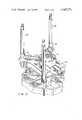
- FIG. 1shows the wellhead accessory connector with a running tool
- FIG. 2is a view with a flowline alignment module
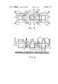
- FIG. 3is a plan view of a retrievable guide pile module and a cantilever well module
- FIG. 4is a side elevation of FIG. 3, and
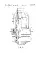
- FIG. 5illustrates the wellhead accessory connector with a tieback assembly in place.
- a temporary guide base(not shown) is lowered to the seabed, and a 36 inch hole may be drilled for a 30 inch casing.
- a permanent guide base 10which has been fastened to the 30 inch wellhead housing 12 through clamp 14 is lowered through the temporary guide base.
- This structurecarries the desired length of 30 inch casing (not shown), and the permanent guide base is placed in a horizontal position on the temporary guide base. The 30 inch housing is then cemented in place.
- the wellhead 16 carrying 20 inch casing 18is lowered and supported from the wellhead housing 12.
- the wellhead body 20is supported on an upwardly facing shoulder 22 of a profile ring 24. This ring is in turn supported on an upwardly facing shoulder 26 of the wellhead housing 12.
- the wellhead housing 12is frequently called a 30 inch housing, and the wellhead 16 a wellhead housing in the art. The above-described terminology will, however, be used in this description.
- the wellhead 16is then cemented into place with additional casing strings later placed therein and cemented as drilling progresses.
- the wellheadincludes the conventional first latch profile 28 at the upper end for the connection of the BOP stack during drilling. This profile may be used for the later connection of a production tree or for the connection of a conductor riser in the event that internal threads 30 are damaged.
- the profile ring 24is connected to the wellhead body 20 by engagement between shoulder 32 and split ring 34.
- This profile ringpreferably has a close fit with the wellhead body since high loads are carried through the profile ring into the wellhead.
- the only investment required for the contingency that one might wish to produce an exploratory wellis the addition of the profile ring 24 with a second latching profile 36.
- an accessory module 38is used. If it is desired to produce the well as a satellite well, the accessory module 38 carries an alignment flange 40 shown in FIG. 2. If additional wells are to be produced, the accessory module 38 carries a cantilever well module 69 with a guide structure 42 as illustrated in FIGS. 3 and 4. If a jacket and platform are to be installed over the wells, the accessory module 38 carries a retrievable guide pile module 43 carrying a cylindrical guide 44.
- the accessory moduleis illustrated in FIG. 1 in its landed but unlocked position and in FIG. 5 in its locked position.
- the accessory moduleincludes a frame 50 with locking dogs 52 attached thereto. These dogs are arranged to annularly surround the wellhead 16 and are held in the frame 50 between support ring 54 and landing ring 56.
- the landing ring 56may be formed of segments which pass between adjacent dogs 52 for attachment to support ring 54.
- a locking cam 58is held in the retracted position before installation of the module by shear pin 60.
- the accessory moduleis lowered on the running tool 62 with guide funnels 64 engaging guide posts 66 of the permanent guide base. This provides general alignment of the module so that the landing ring 56 clears the upper end of the wellhead.
- landing ring 56engages shoulder 22, landing is detected by relaxation of the load.
- locking cylinders 68are energized driving the locking cam downwardly and forcing locking dogs 52 into engagement with the second profile 36.
- the camming actionoperates through a 4 degree angle so that the cam will remain in place once it is driven down. If desired, an additional locking mechanism may be added to provide increased assurance of the lock.
- accessory moduleis now held in a precise alignment with respect to the wellhead housing 12. Accordingly, accessory apparatus located on this accessory module is in itself in precise relationship with the wellhead housing; and accordingly, remote operating equipment can be successfully designed to make connections to production trees and for other required operations.
- a landing shoulderis readily provided. It is less expensive to fabricate since it can readily be supplied as a separate forging without making the wellhead forging oversized with the required machining away of material. In the rare case where a high stress concentration in the profile connection combines with an undetected material defect, cracking of the landing ring would not result in failure, but the system would continue to operate.
- the accessory module 38is formed as a flowline alignment module by including alignment flange 40 on the frame.
- the approximate location of the accessory module and the angular orientationis maintained by the interaction between guide funnels 64 and posts 66.
- Precise spatial relationship between the wellhead 16 and the alignment flange 40is held by the locking dog arrangement. This provides a strong structure which passes loads directly into the wellhead 16 and therethrough into the multiple casing strings which are cemented into the seabed.
- the precise alignmentpermits remote operation of a flowline pull-in tool and remote stroking and connection of the production tree sales line. It also holds the flowline in place once it is pulled into position.
- the cantilever well module 69which will provide the spacing and guidance for additional wells.
- the cantilever modulehas a structure 71 which is attached to the base module 38 by pins 74 fitting into openings in the base module. Hooks located on the cantilever module also engage rod 72, to preclude the module swinging outwardly.
- the cantilever well module 69also carries engaging rings 76 which engage the guide posts 66 of the permanent guide base, and carries on its own structure 71 additional guide posts 78 from which additional cantilever well modules may be later hung.
- a retrievable guide pile module 43is used for this purpose. It has a structure 77 supported from the base module 38 in much the same manner as the cantilever well module. After installing the guide pile through cylindrical guide 44, the module is retrieved by engaging a J groove in opening 79 with a running tool. The module may then be retrieved to the surface. The guide pile is left spaced away from the wellhead and is ready at this time to accept the platform jacket.
- FIG. 5illustrates the dogs 52 in their locked position engaging the second profile 36 for holding the base module 38 in place.
- the tieback assembly 80which is engaged and locked to the upper end of the wellhead 16 with lockdown nut 82.
- Thisis simply one illustration of utilization of the upper end of the wellhead housing with the base module in place.
- a production treecould be in place engaging first profile 28 or in the event of damage to the internal threads of the housing, a riser tieback assembly could be latched onto the first profile.
- the second profile 36is located on the lower end of the wellhead only a short distance above the wellhead housing 12.
- the profile ring 24is extended beyond the size required for landing the wellhead 16 in the wellhead housing 12, and a second latching profile is provided on this profile ring. No additional investment is required except in those situations where some utilization of the exploratory well is desired. There is no additional investment in strengthening the permanent guide base or the wellhead housing nor is it required that precision be required in the manufacture or design to provide for later remote subsea work.
- a base moduleis provided with means for engaging this profile so that it may be held in precise relationship with the ability to carry substantial load into the wellhead.
- the base modulemay carry the various described components so that complete flexibility as to decisions for future utilization of the exploratory well is available.
Landscapes
- Life Sciences & Earth Sciences (AREA)
- Engineering & Computer Science (AREA)
- Geology (AREA)
- Mining & Mineral Resources (AREA)
- Physics & Mathematics (AREA)
- Environmental & Geological Engineering (AREA)
- Fluid Mechanics (AREA)
- General Life Sciences & Earth Sciences (AREA)
- Geochemistry & Mineralogy (AREA)
- Earth Drilling (AREA)
Abstract
Description
Claims (10)
Priority Applications (1)
| Application Number | Priority Date | Filing Date | Title |
|---|---|---|---|
| US06/261,091US4387771A (en) | 1981-02-17 | 1980-10-14 | Wellhead system for exploratory wells |
Applications Claiming Priority (1)
| Application Number | Priority Date | Filing Date | Title |
|---|---|---|---|
| US06/261,091US4387771A (en) | 1981-02-17 | 1980-10-14 | Wellhead system for exploratory wells |
Publications (1)
| Publication Number | Publication Date |
|---|---|
| US4387771Atrue US4387771A (en) | 1983-06-14 |
Family
ID=22991919
Family Applications (1)
| Application Number | Title | Priority Date | Filing Date |
|---|---|---|---|
| US06/261,091Expired - Fee RelatedUS4387771A (en) | 1981-02-17 | 1980-10-14 | Wellhead system for exploratory wells |
Country Status (1)
| Country | Link |
|---|---|
| US (1) | US4387771A (en) |
Cited By (29)
| Publication number | Priority date | Publication date | Assignee | Title |
|---|---|---|---|---|
| US4591296A (en)* | 1983-09-23 | 1986-05-27 | Smith International, Inc. | Temporary guide base retrieval method and apparatus |
| US4611661A (en)* | 1985-04-15 | 1986-09-16 | Vetco Offshore Industries, Inc. | Retrievable exploration guide base/completion guide base system |
| US4630680A (en)* | 1983-01-27 | 1986-12-23 | Hydril Company | Well control method and apparatus |
| US4681173A (en)* | 1985-07-19 | 1987-07-21 | Texaco Inc. | Method and apparatus for drilling a group of subsea wells |
| US4706757A (en)* | 1985-05-21 | 1987-11-17 | Amoco Corporation | Wellhead supported subsea templates and methods |
| FR2610366A1 (en)* | 1987-01-13 | 1988-08-05 | Petroleo Brasileiro Sa | METHOD AND INSTALLATION FOR DEEP WATER EXECUTION OF OPERATIONS FOR DRILLING AN OIL WELL AND COMPLETION THEREON |
| US5005650A (en)* | 1989-02-23 | 1991-04-09 | The British Petroleum Company P.L.C. | Multi-purpose well head equipment |
| US5069287A (en)* | 1990-08-01 | 1991-12-03 | Fmc Corporation | Retrievable guide base for subsea well |
| US5088556A (en)* | 1990-08-01 | 1992-02-18 | Fmc Corporation | Subsea well guide base running tool |
| US5107931A (en)* | 1990-11-14 | 1992-04-28 | Valka William A | Temporary abandonment cap and tool |
| US5129460A (en)* | 1991-04-30 | 1992-07-14 | Shell Offshore Inc. | Guide base cover |
| US5158141A (en)* | 1988-10-14 | 1992-10-27 | Den Norske Stats Oljeselskap A.S | Coupling arrangement for components in subsea structures and a remotely operated tool unit for handling such components |
| NL9301002A (en)* | 1993-06-10 | 1995-01-02 | Volker Stevin Offshore B V | Offshore production unit, and method for starting production of an offshore extraction field |
| US7487837B2 (en)* | 2004-11-23 | 2009-02-10 | Weatherford/Lamb, Inc. | Riser rotating control device |
| US20090314494A1 (en)* | 2008-06-23 | 2009-12-24 | Vetco Gray Inc. | Wellhead Housing Bootstrap Device |
| US7836946B2 (en) | 2002-10-31 | 2010-11-23 | Weatherford/Lamb, Inc. | Rotating control head radial seal protection and leak detection systems |
| US7926593B2 (en) | 2004-11-23 | 2011-04-19 | Weatherford/Lamb, Inc. | Rotating control device docking station |
| US7997345B2 (en) | 2007-10-19 | 2011-08-16 | Weatherford/Lamb, Inc. | Universal marine diverter converter |
| US8286734B2 (en) | 2007-10-23 | 2012-10-16 | Weatherford/Lamb, Inc. | Low profile rotating control device |
| US8322432B2 (en) | 2009-01-15 | 2012-12-04 | Weatherford/Lamb, Inc. | Subsea internal riser rotating control device system and method |
| US8347983B2 (en) | 2009-07-31 | 2013-01-08 | Weatherford/Lamb, Inc. | Drilling with a high pressure rotating control device |
| US8347982B2 (en) | 2010-04-16 | 2013-01-08 | Weatherford/Lamb, Inc. | System and method for managing heave pressure from a floating rig |
| US20130098626A1 (en)* | 2011-10-20 | 2013-04-25 | Vetco Gray Inc. | Soft Landing System and Method of Achieving Same |
| US8826988B2 (en) | 2004-11-23 | 2014-09-09 | Weatherford/Lamb, Inc. | Latch position indicator system and method |
| US8844652B2 (en) | 2007-10-23 | 2014-09-30 | Weatherford/Lamb, Inc. | Interlocking low profile rotating control device |
| US9175542B2 (en) | 2010-06-28 | 2015-11-03 | Weatherford/Lamb, Inc. | Lubricating seal for use with a tubular |
| US9359853B2 (en) | 2009-01-15 | 2016-06-07 | Weatherford Technology Holdings, Llc | Acoustically controlled subsea latching and sealing system and method for an oilfield device |
| WO2018117861A1 (en)* | 2016-12-23 | 2018-06-28 | Statoil Petroleum As | Subsea assembly modularisation |
| US10041335B2 (en) | 2008-03-07 | 2018-08-07 | Weatherford Technology Holdings, Llc | Switching device for, and a method of switching, a downhole tool |
Citations (7)
| Publication number | Priority date | Publication date | Assignee | Title |
|---|---|---|---|---|
| US3143171A (en)* | 1961-04-11 | 1964-08-04 | Shell Oil Co | Underwater well guide system |
| US3242991A (en)* | 1962-08-07 | 1966-03-29 | Shell Oil Co | Underwater wellhead with re-entry lubricator |
| US3347567A (en)* | 1963-11-29 | 1967-10-17 | Regan Forge & Eng Co | Double tapered guidance apparatus |
| US3618661A (en)* | 1969-08-15 | 1971-11-09 | Shell Oil Co | Apparatus and method for drilling and producing multiple underwater wells |
| US3716100A (en)* | 1971-01-12 | 1973-02-13 | Vetco Offshore Ind Inc | Apparatus for aligning and connecting flowlines |
| US3834460A (en)* | 1971-12-27 | 1974-09-10 | Subsea Equipment Ass Ltd | Well-head assembly |
| US4192383A (en)* | 1978-05-02 | 1980-03-11 | Armco Inc. | Offshore multiple well drilling and production apparatus |
- 1980
- 1980-10-14USUS06/261,091patent/US4387771A/ennot_activeExpired - Fee Related
Patent Citations (7)
| Publication number | Priority date | Publication date | Assignee | Title |
|---|---|---|---|---|
| US3143171A (en)* | 1961-04-11 | 1964-08-04 | Shell Oil Co | Underwater well guide system |
| US3242991A (en)* | 1962-08-07 | 1966-03-29 | Shell Oil Co | Underwater wellhead with re-entry lubricator |
| US3347567A (en)* | 1963-11-29 | 1967-10-17 | Regan Forge & Eng Co | Double tapered guidance apparatus |
| US3618661A (en)* | 1969-08-15 | 1971-11-09 | Shell Oil Co | Apparatus and method for drilling and producing multiple underwater wells |
| US3716100A (en)* | 1971-01-12 | 1973-02-13 | Vetco Offshore Ind Inc | Apparatus for aligning and connecting flowlines |
| US3834460A (en)* | 1971-12-27 | 1974-09-10 | Subsea Equipment Ass Ltd | Well-head assembly |
| US4192383A (en)* | 1978-05-02 | 1980-03-11 | Armco Inc. | Offshore multiple well drilling and production apparatus |
Non-Patent Citations (1)
| Title |
|---|
| Synder, Robert E., New Concept Unveiled for Subsea Completion, Production", World Oil, Sep. 1976, pp. 41-45. |
Cited By (59)
| Publication number | Priority date | Publication date | Assignee | Title |
|---|---|---|---|---|
| US4630680A (en)* | 1983-01-27 | 1986-12-23 | Hydril Company | Well control method and apparatus |
| US4591296A (en)* | 1983-09-23 | 1986-05-27 | Smith International, Inc. | Temporary guide base retrieval method and apparatus |
| US4611661A (en)* | 1985-04-15 | 1986-09-16 | Vetco Offshore Industries, Inc. | Retrievable exploration guide base/completion guide base system |
| FR2580329A1 (en)* | 1985-04-15 | 1986-10-17 | Vetco Offshore Ind Inc | SYSTEM AND METHOD FOR CONVERTING A PRODUCTIVE WELL EXPLORATION WELL, LOCKING DEVICE EACH OTHER OF BOTH PARTS OF A PERMANENT BASE PLATE AND BASE PLATE FOR USE IN DRILLING AND PRODUCTION AT SEA |
| US4706757A (en)* | 1985-05-21 | 1987-11-17 | Amoco Corporation | Wellhead supported subsea templates and methods |
| US4681173A (en)* | 1985-07-19 | 1987-07-21 | Texaco Inc. | Method and apparatus for drilling a group of subsea wells |
| FR2610366A1 (en)* | 1987-01-13 | 1988-08-05 | Petroleo Brasileiro Sa | METHOD AND INSTALLATION FOR DEEP WATER EXECUTION OF OPERATIONS FOR DRILLING AN OIL WELL AND COMPLETION THEREON |
| US5158141A (en)* | 1988-10-14 | 1992-10-27 | Den Norske Stats Oljeselskap A.S | Coupling arrangement for components in subsea structures and a remotely operated tool unit for handling such components |
| US5005650A (en)* | 1989-02-23 | 1991-04-09 | The British Petroleum Company P.L.C. | Multi-purpose well head equipment |
| US5069287A (en)* | 1990-08-01 | 1991-12-03 | Fmc Corporation | Retrievable guide base for subsea well |
| US5088556A (en)* | 1990-08-01 | 1992-02-18 | Fmc Corporation | Subsea well guide base running tool |
| US5107931A (en)* | 1990-11-14 | 1992-04-28 | Valka William A | Temporary abandonment cap and tool |
| US5129460A (en)* | 1991-04-30 | 1992-07-14 | Shell Offshore Inc. | Guide base cover |
| NL9301002A (en)* | 1993-06-10 | 1995-01-02 | Volker Stevin Offshore B V | Offshore production unit, and method for starting production of an offshore extraction field |
| US7934545B2 (en) | 2002-10-31 | 2011-05-03 | Weatherford/Lamb, Inc. | Rotating control head leak detection systems |
| US8113291B2 (en) | 2002-10-31 | 2012-02-14 | Weatherford/Lamb, Inc. | Leak detection method for a rotating control head bearing assembly and its latch assembly using a comparator |
| US7836946B2 (en) | 2002-10-31 | 2010-11-23 | Weatherford/Lamb, Inc. | Rotating control head radial seal protection and leak detection systems |
| US8714240B2 (en) | 2002-10-31 | 2014-05-06 | Weatherford/Lamb, Inc. | Method for cooling a rotating control device |
| US8353337B2 (en) | 2002-10-31 | 2013-01-15 | Weatherford/Lamb, Inc. | Method for cooling a rotating control head |
| US8826988B2 (en) | 2004-11-23 | 2014-09-09 | Weatherford/Lamb, Inc. | Latch position indicator system and method |
| US7487837B2 (en)* | 2004-11-23 | 2009-02-10 | Weatherford/Lamb, Inc. | Riser rotating control device |
| US8939235B2 (en) | 2004-11-23 | 2015-01-27 | Weatherford/Lamb, Inc. | Rotating control device docking station |
| US9404346B2 (en) | 2004-11-23 | 2016-08-02 | Weatherford Technology Holdings, Llc | Latch position indicator system and method |
| US9784073B2 (en) | 2004-11-23 | 2017-10-10 | Weatherford Technology Holdings, Llc | Rotating control device docking station |
| US7926593B2 (en) | 2004-11-23 | 2011-04-19 | Weatherford/Lamb, Inc. | Rotating control device docking station |
| US8701796B2 (en) | 2004-11-23 | 2014-04-22 | Weatherford/Lamb, Inc. | System for drilling a borehole |
| US8408297B2 (en) | 2004-11-23 | 2013-04-02 | Weatherford/Lamb, Inc. | Remote operation of an oilfield device |
| US10024154B2 (en) | 2004-11-23 | 2018-07-17 | Weatherford Technology Holdings, Llc | Latch position indicator system and method |
| US7997345B2 (en) | 2007-10-19 | 2011-08-16 | Weatherford/Lamb, Inc. | Universal marine diverter converter |
| US10087701B2 (en) | 2007-10-23 | 2018-10-02 | Weatherford Technology Holdings, Llc | Low profile rotating control device |
| US8844652B2 (en) | 2007-10-23 | 2014-09-30 | Weatherford/Lamb, Inc. | Interlocking low profile rotating control device |
| US8286734B2 (en) | 2007-10-23 | 2012-10-16 | Weatherford/Lamb, Inc. | Low profile rotating control device |
| US9004181B2 (en) | 2007-10-23 | 2015-04-14 | Weatherford/Lamb, Inc. | Low profile rotating control device |
| US10041335B2 (en) | 2008-03-07 | 2018-08-07 | Weatherford Technology Holdings, Llc | Switching device for, and a method of switching, a downhole tool |
| US20090314494A1 (en)* | 2008-06-23 | 2009-12-24 | Vetco Gray Inc. | Wellhead Housing Bootstrap Device |
| US8220550B2 (en)* | 2008-06-23 | 2012-07-17 | Vetco Gray Inc. | Wellhead housing bootstrap device |
| US9359853B2 (en) | 2009-01-15 | 2016-06-07 | Weatherford Technology Holdings, Llc | Acoustically controlled subsea latching and sealing system and method for an oilfield device |
| US8770297B2 (en) | 2009-01-15 | 2014-07-08 | Weatherford/Lamb, Inc. | Subsea internal riser rotating control head seal assembly |
| US8322432B2 (en) | 2009-01-15 | 2012-12-04 | Weatherford/Lamb, Inc. | Subsea internal riser rotating control device system and method |
| US8636087B2 (en) | 2009-07-31 | 2014-01-28 | Weatherford/Lamb, Inc. | Rotating control system and method for providing a differential pressure |
| US9334711B2 (en) | 2009-07-31 | 2016-05-10 | Weatherford Technology Holdings, Llc | System and method for cooling a rotating control device |
| US8347983B2 (en) | 2009-07-31 | 2013-01-08 | Weatherford/Lamb, Inc. | Drilling with a high pressure rotating control device |
| US8347982B2 (en) | 2010-04-16 | 2013-01-08 | Weatherford/Lamb, Inc. | System and method for managing heave pressure from a floating rig |
| US9260927B2 (en) | 2010-04-16 | 2016-02-16 | Weatherford Technology Holdings, Llc | System and method for managing heave pressure from a floating rig |
| US8863858B2 (en) | 2010-04-16 | 2014-10-21 | Weatherford/Lamb, Inc. | System and method for managing heave pressure from a floating rig |
| US9175542B2 (en) | 2010-06-28 | 2015-11-03 | Weatherford/Lamb, Inc. | Lubricating seal for use with a tubular |
| US8931561B2 (en)* | 2011-10-20 | 2015-01-13 | Vetco Gray Inc. | Soft landing system and method of achieving same |
| US20130098626A1 (en)* | 2011-10-20 | 2013-04-25 | Vetco Gray Inc. | Soft Landing System and Method of Achieving Same |
| US9347292B2 (en) | 2011-10-20 | 2016-05-24 | Vetco Gray Inc. | Soft landing system and method of achieving same |
| WO2018117861A1 (en)* | 2016-12-23 | 2018-06-28 | Statoil Petroleum As | Subsea assembly modularisation |
| GB2573414A (en)* | 2016-12-23 | 2019-11-06 | Equinor Energy As | Subsea assembly modularisation |
| US20190376250A1 (en)* | 2016-12-23 | 2019-12-12 | Equinor Energy As | Subsea assembly modularisation |
| GB2573414B (en)* | 2016-12-23 | 2022-03-30 | Equinor Energy As | Subsea assembly modularisation |
| US11542677B2 (en) | 2016-12-23 | 2023-01-03 | Equinor Energy As | Subsea assembly modularization |
| US11549231B2 (en) | 2016-12-23 | 2023-01-10 | Equinor Energy As | Suction anchor for a subsea well |
| AU2017379549B2 (en)* | 2016-12-23 | 2023-07-06 | Equinor Energy As | Subsea assembly modularisation |
| US11859364B2 (en)* | 2016-12-23 | 2024-01-02 | Equinor Energy As | Subsea assembly modularisation |
| US12215472B2 (en) | 2016-12-23 | 2025-02-04 | Equinor Energy As | Subsea assembly modularization |
| US12338595B2 (en) | 2016-12-23 | 2025-06-24 | Equinor Energy As | Foundation modularization |
Similar Documents
| Publication | Publication Date | Title |
|---|---|---|
| US4387771A (en) | Wellhead system for exploratory wells | |
| US6719059B2 (en) | Plug installation system for deep water subsea wells | |
| US4611661A (en) | Retrievable exploration guide base/completion guide base system | |
| US7143830B2 (en) | Apparatus and method for installation of subsea well completion systems | |
| US7032673B2 (en) | Orientation system for a subsea well | |
| US20070034379A1 (en) | Plug installation system for deep water subsea wells | |
| US3779313A (en) | Le connecting apparatus for subsea wellhead | |
| US4067062A (en) | Hydraulic set tubing hanger | |
| US3618661A (en) | Apparatus and method for drilling and producing multiple underwater wells | |
| US5005650A (en) | Multi-purpose well head equipment | |
| US6805200B2 (en) | Horizontal spool tree wellhead system and method | |
| US3050140A (en) | Method and apparatus for installing guide lines at underwater wellheads | |
| US6978839B2 (en) | Internal connection of tree to wellhead housing | |
| US5722796A (en) | Hinge-over subsea template production system | |
| US3721294A (en) | Underwater pipe connection apparatus | |
| US3378066A (en) | Underwater wellhead connection | |
| US3527294A (en) | Underwater exploration and completion system | |
| US5069287A (en) | Retrievable guide base for subsea well | |
| US3062288A (en) | Underwater dual tubing well completion | |
| US4105068A (en) | Apparatus for producing oil and gas offshore | |
| US4877088A (en) | Process and equipment for oil well drilling and completing operations in deep water | |
| US5080173A (en) | Tieback wellhead system with sidetrack facilities | |
| US5088556A (en) | Subsea well guide base running tool | |
| US3322191A (en) | Underwater well drilling method | |
| US5129460A (en) | Guide base cover |
Legal Events
| Date | Code | Title | Description |
|---|---|---|---|
| AS | Assignment | Owner name:VETCO OFFSHORE, INC., VENTURA, CA. A CORP. OF DE. Free format text:ASSIGNMENT OF ASSIGNORS INTEREST.;ASSIGNOR:JONES DARRELL L.;REEL/FRAME:003882/0001 Effective date:19810106 Owner name:VETCO OFFSHORE, INC., CALIFORNIA Free format text:ASSIGNMENT OF ASSIGNORS INTEREST;ASSIGNOR:JONES DARRELL L.;REEL/FRAME:003882/0001 Effective date:19810106 | |
| FEPP | Fee payment procedure | Free format text:PAYER NUMBER DE-ASSIGNED (ORIGINAL EVENT CODE: RMPN); ENTITY STATUS OF PATENT OWNER: LARGE ENTITY Free format text:PAYOR NUMBER ASSIGNED (ORIGINAL EVENT CODE: ASPN); ENTITY STATUS OF PATENT OWNER: LARGE ENTITY | |
| FEPP | Fee payment procedure | Free format text:PAYER NUMBER DE-ASSIGNED (ORIGINAL EVENT CODE: RMPN); ENTITY STATUS OF PATENT OWNER: LARGE ENTITY Free format text:PAYOR NUMBER ASSIGNED (ORIGINAL EVENT CODE: ASPN); ENTITY STATUS OF PATENT OWNER: LARGE ENTITY | |
| FEPP | Fee payment procedure | Free format text:PAYOR NUMBER ASSIGNED (ORIGINAL EVENT CODE: ASPN); ENTITY STATUS OF PATENT OWNER: LARGE ENTITY Free format text:PAYER NUMBER DE-ASSIGNED (ORIGINAL EVENT CODE: RMPN); ENTITY STATUS OF PATENT OWNER: LARGE ENTITY | |
| AS | Assignment | Owner name:VETCO OFFSHORE INDUSTRIES, INC., 7135 ARDMORE ROAD Free format text:ASSIGNMENT OF ASSIGNORS INTEREST.;ASSIGNOR:VETCO OFFSHORE, INC., A CORP. OF DE.;REEL/FRAME:004572/0533 Effective date:19860421 | |
| AS | Assignment | Owner name:CITIBANK, N.A., Free format text:SECURITY INTEREST;ASSIGNOR:VETCO GRAY INC., A DE. CORP.;REEL/FRAME:004739/0780 Effective date:19861124 | |
| AS | Assignment | Owner name:VETCO GRAY INC., Free format text:MERGER;ASSIGNORS:GRAY TOOL COMPANY, A TX. CORP. (INTO);VETCO OFFSHORE INDUSTRIES, INC., A CORP. (CHANGED TO);REEL/FRAME:004748/0332 Effective date:19861217 | |
| FEPP | Fee payment procedure | Free format text:PAYOR NUMBER ASSIGNED (ORIGINAL EVENT CODE: ASPN); ENTITY STATUS OF PATENT OWNER: LARGE ENTITY Free format text:PAYER NUMBER DE-ASSIGNED (ORIGINAL EVENT CODE: RMPN); ENTITY STATUS OF PATENT OWNER: LARGE ENTITY | |
| FEPP | Fee payment procedure | Free format text:PAYOR NUMBER ASSIGNED (ORIGINAL EVENT CODE: ASPN); ENTITY STATUS OF PATENT OWNER: LARGE ENTITY Free format text:PAYER NUMBER DE-ASSIGNED (ORIGINAL EVENT CODE: RMPN); ENTITY STATUS OF PATENT OWNER: LARGE ENTITY | |
| LAPS | Lapse for failure to pay maintenance fees | ||
| FP | Lapsed due to failure to pay maintenance fee | Effective date:19950614 | |
| STCH | Information on status: patent discontinuation | Free format text:PATENT EXPIRED DUE TO NONPAYMENT OF MAINTENANCE FEES UNDER 37 CFR 1.362 |