US4387727A - Coaxial service kit - Google Patents
Coaxial service kitDownload PDFInfo
- Publication number
- US4387727A US4387727AUS06/248,735US24873581AUS4387727AUS 4387727 AUS4387727 AUS 4387727AUS 24873581 AUS24873581 AUS 24873581AUS 4387727 AUS4387727 AUS 4387727A
- Authority
- US
- United States
- Prior art keywords
- conductor coil
- cut end
- coil
- lumen
- outer conductor
- Prior art date
- Legal status (The legal status is an assumption and is not a legal conclusion. Google has not performed a legal analysis and makes no representation as to the accuracy of the status listed.)
- Expired - Fee Related
Links
Images

Classifications
- A—HUMAN NECESSITIES
- A61—MEDICAL OR VETERINARY SCIENCE; HYGIENE
- A61N—ELECTROTHERAPY; MAGNETOTHERAPY; RADIATION THERAPY; ULTRASOUND THERAPY
- A61N1/00—Electrotherapy; Circuits therefor
- A61N1/02—Details
- A61N1/04—Electrodes
- A61N1/05—Electrodes for implantation or insertion into the body, e.g. heart electrode
- H—ELECTRICITY
- H01—ELECTRIC ELEMENTS
- H01R—ELECTRICALLY-CONDUCTIVE CONNECTIONS; STRUCTURAL ASSOCIATIONS OF A PLURALITY OF MUTUALLY-INSULATED ELECTRICAL CONNECTING ELEMENTS; COUPLING DEVICES; CURRENT COLLECTORS
- H01R4/00—Electrically-conductive connections between two or more conductive members in direct contact, i.e. touching one another; Means for effecting or maintaining such contact; Electrically-conductive connections having two or more spaced connecting locations for conductors and using contact members penetrating insulation
- H01R4/24—Connections using contact members penetrating or cutting insulation or cable strands
- H—ELECTRICITY
- H01—ELECTRIC ELEMENTS
- H01R—ELECTRICALLY-CONDUCTIVE CONNECTIONS; STRUCTURAL ASSOCIATIONS OF A PLURALITY OF MUTUALLY-INSULATED ELECTRICAL CONNECTING ELEMENTS; COUPLING DEVICES; CURRENT COLLECTORS
- H01R9/00—Structural associations of a plurality of mutually-insulated electrical connecting elements, e.g. terminal strips or terminal blocks; Terminals or binding posts mounted upon a base or in a case; Bases therefor
- H01R9/03—Connectors arranged to contact a plurality of the conductors of a multiconductor cable, e.g. tapping connections
- H01R9/05—Connectors arranged to contact a plurality of the conductors of a multiconductor cable, e.g. tapping connections for coaxial cables
Definitions
- the present inventionrelates generally to implantable medical devices and more specifically relates to electrical connection means for chronic implantation.
- bipolar leadshave typically resulted in reuse of the lead in unipolar mode in those instances wherein a splice is required. It has been determined to be desirable to be able to splice bipolar leads having coaxial conductors. Any such splicing technique must, of course, be executed within the sterile environment of the operating room since the splice will be chronically implanted. This means that the techniques employed require easy and rapid deployment.
- the present inventionpermits rapid and reliable splicing of a coaxial body implantable lead. Electrical contact to the inner coil is sustained by a conductive pin which is inserted within the inner conductor coil. A barb at the end of this pin allows the pin to be screwed into the inner conductor coil. In this manner positive and reliable electrical contact is sustained. A set screw within the main housing of the device mechanically and electrically secures the conductive pin.
- An insulating sleeveis interposed between the conductive pin and the outer conductor coil of the lead to be spliced. This sleeve insures that the outer coil will not develop a short circuit to either the inner conductor coil or to the electrically common conductive pin. Electrical and mechanical contact is sustained between the main housing and the outer conductor coil by a set screw having a pointed tip. This set screw is screwed through the outer sheath of the body implantable lead and into the outer conductor coil. In this manner, good electrical and mechanical contact is sustained.
- the main housingmay be permanently attached to a length of body implantable lead as in the case of the preferred embodiment or it may contain a double-ended splicing capability to enable splicing to another portion of the same body implantable lead.
- a third optionplaces a standard type implantable connector at one end of the main housing and a fourth embodiment uses the main housing as a portion of an implantable pulse generator.
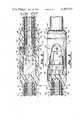
- FIG. 1is a plan view of the coaxial service kit as it appears with the splice complete, ready for chronic implantation.
- FIG. 2is a side sectional view of the apparatus of FIG. 1.
- FIG. 3is a top sectional view showing the method of connection between the set screws and the permanently attached portion of the lead.
- FIG. 4is a sectional view of the insulating sleeve.
- FIG. 5is a side view of the conducting pin showing the attached barb.
- the main housing of the splicing kithas a permanently attached portion of a two-conductor coaxial lead which itself may be attached to in-line connector terminals (not shown).
- the main teaching, however, of this disclosurewill allow one to readily apply the present invention to other configurations. Examples of related configurations include, for example, a housing with a standard connector receptacle. Also easily accomplished by those of ordinary skill in the art is a two-ended adaptor housing having capability for splicing at either end. Of course, the present invention is also applicable to body implantable leads having more than two conductors.
- FIG. 1is a plan view of the preferred embodiment of the present invention.
- main housing 10is the place at which permanently attached two conductor coaxial body implantable lead 20 is joined with the spliced end of two-conductor coaxial body implantable lead 30.
- Medical adhesive 40 or other suitable implantable adhesivemay be used to facilitate the seal between body implantable lead 30 and main housing 10. Notice that grooves 42 and 46 are available for sutures.
- Set screw protection 50 and 52may be provided using medical adhesive to prevent the ingress of body fluids to the apertures containing the set screws for making the permanent attachment.
- Main housing 10, set screw protections 50 and 52, the outer sheath of two-conductor coaxial body implantable lead 20 and medical adhesive 40are all of body implantable materials, suitable for chronic implantation.
- FIG. 2is a cross sectinal view of the apparatus shown in FIG. 1.
- body implantable lead 30To create a proper splice, body implantable lead 30 must be cut perpendicular to its longitudinal axis at the end to be spliced.
- the distal end 70 of conducting pin 72is inserted within the lumen defined by the interior of conducting coil 36.
- Conducting pin 72is made of stainless steel or other body compatible conducting material.
- conducting pin 72has a notch 74 as shown. Notch 74 enables conducting pin 72 to be screwed into conductor coil 36.
- the shoulder 76 of conducting pin 72insures that a good mechanical fit is obtained as the conductor coils 36 are compressed together.
- the conducting pin 72is screwed into inner conducting coil 36 until conducting coil 36 rests firmly against shoulder 76. As shown, this causes the inner conducting coil 36 to recede from the proximal end of the splice because of the distance between shoulder 76 and shoulder 62.
- the inner conductor coil 36 and insulating tube 34are loosely arranged within the outer conductor coil 32 and sheath 38. Consequently, the inner conductor coil 36 and sheath 34 can be compressed and retracted into the lumen of the conductor coil 32.
- Insulating sleeve 60Before inserting conducting pin 72, insulating sleeve 60 is positioned over conducting pin 72.
- Insulating sleeve 60is made of a body compatible rigid insulating material such as urethane. Insulating sleeve 60 must be sufficiently rigid to protect against penetration of pointed set screw 56 (see below). Insulating sleeve 60 is positioned rigidly against conducting pin 72 at shoulder 78. Insulating sleeve 60 is tapered at positions 66 and 69 as shown. This causes a tight fit between the distal end of insulating sleeve 60 and inner insulating sheath 34 as shown.
- conducting pin 72(and thus inner conducting coil 36) is sustained by set screw 54 being screwed into intimate contact with conducting pin 72 as shown. This establishes contact with inner adaptor conductor 14 which is electrically connected to inner coil 26 of permanently attached, body implantable lead 20. This connection is shown in greater detail in FIG. 3 and is discussed below.
- set screw protection 50 and 52 of medical adhesiveThis prevents the ingress of body fluids to the interior of main housing 10.
- FIG. 3is a top sectional view showing inner adaptor conductors 14 and 16. Notice that they are placed in intimate contact with set screws 54 and 56, and are connected electrically at the other end with inner conductor coil 26 and outer conductor coil 22 respectively of body implantable lead 20.
- FIG. 4is a detailed side sectional view of insulating sleeve 60. It is fabricated of a body compatible rigid insulating material such as urethane. It contains a longitudinal lumen 64 which is of sufficient diameter for the insertion of conducting pin 72. Shoulder 62 is to establish secure mechanical contact with the proximal end of outer conductor coil 32 and the outer insulating sheath of body implantable lead 30. The distal end of insulating sleeve 60 is pointed at 69, allowing for the secure mechanical contact between outer conductor coil 32 and inner insulating sheath 34. The pointed distal end creates enlargement 68 of lumen 64 as shown. Within this enlargement will be found inner conductor coil 36 (see also FIG. 2). Inner insulating sheath 34 is enlarged by shoulder 66 as shown. Notice that shoulder 66 is slanted to encourage the maximum travel of inner insulating sheath 34 which insures a tight insulated fit.
- FIG. 5is a side view of insulating pin 72.
- Distal portion 70is of an outside diameter sufficiently small to readily be inserted within inner conducting coil 36.
- Notch 74must be of sufficient size to create a radius of curvature which enables conducting pin 72 to be screwed inner conducting coil 36. Shoulder 76 engages inner conducting coil 36 and inner insulating sheath 34.
- Conducting pin 72is made of a body compatible, low electrical resistance material. Stainless steel No. 304 is preferred.
Landscapes
- Health & Medical Sciences (AREA)
- Cardiology (AREA)
- Heart & Thoracic Surgery (AREA)
- Engineering & Computer Science (AREA)
- Biomedical Technology (AREA)
- Nuclear Medicine, Radiotherapy & Molecular Imaging (AREA)
- Radiology & Medical Imaging (AREA)
- Life Sciences & Earth Sciences (AREA)
- Animal Behavior & Ethology (AREA)
- General Health & Medical Sciences (AREA)
- Public Health (AREA)
- Veterinary Medicine (AREA)
- Electrotherapy Devices (AREA)
Abstract
Description
Claims (17)
Priority Applications (1)
| Application Number | Priority Date | Filing Date | Title |
|---|---|---|---|
| US06/248,735US4387727A (en) | 1981-03-30 | 1981-03-30 | Coaxial service kit |
Applications Claiming Priority (1)
| Application Number | Priority Date | Filing Date | Title |
|---|---|---|---|
| US06/248,735US4387727A (en) | 1981-03-30 | 1981-03-30 | Coaxial service kit |
Publications (1)
| Publication Number | Publication Date |
|---|---|
| US4387727Atrue US4387727A (en) | 1983-06-14 |
Family
ID=22940443
Family Applications (1)
| Application Number | Title | Priority Date | Filing Date |
|---|---|---|---|
| US06/248,735Expired - Fee RelatedUS4387727A (en) | 1981-03-30 | 1981-03-30 | Coaxial service kit |
Country Status (1)
| Country | Link |
|---|---|
| US (1) | US4387727A (en) |
Cited By (29)
| Publication number | Priority date | Publication date | Assignee | Title |
|---|---|---|---|---|
| US4485268A (en)* | 1983-06-13 | 1984-11-27 | Minnesota Mining And Manufacturing | Sealing device for an electrical connector and method therefor |
| US4572605A (en)* | 1984-08-09 | 1986-02-25 | Medtronic, Inc. | Injection molded in-line connector assembly for bipolar leads |
| US4764132A (en)* | 1986-03-28 | 1988-08-16 | Siemens-Pacesetter, Inc. | Pacemaker connector block for proximal ring electrode |
| US4922607A (en)* | 1988-05-25 | 1990-05-08 | Medtronic, Inc. | Method of fabrication an in-line, multipolar electrical connector |
| US4951687A (en)* | 1989-01-31 | 1990-08-28 | Medtronic, Inc. | Medical electrical lead connector |
| US5007435A (en)* | 1988-05-25 | 1991-04-16 | Medtronic, Inc. | Connector for multiconductor pacing leads |
| EP0343402A3 (en)* | 1988-05-25 | 1991-06-05 | Medtronic, Inc. | Connector pin assembly and method of fabrication. |
| US5036862A (en)* | 1987-04-06 | 1991-08-06 | Cordis Corporation | Implantable, self-retaining lead |
| EP0491979A1 (en)* | 1990-12-22 | 1992-07-01 | Peter Dr. Ing. Osypka | Pacemaker catheter with two poles |
| US5152298A (en)* | 1991-04-16 | 1992-10-06 | Siemens Pacesetter, Inc. | Threaded suture sleeve |
| US5242431A (en)* | 1992-06-11 | 1993-09-07 | Siemens Pacesetter, Inc. | Suture sleeve assembly with slidable compression collar |
| EP0587379A3 (en)* | 1992-09-04 | 1994-12-28 | Siemens Ag | Coaxial two-pin connector for medical implantable device. |
| US5476493A (en)* | 1993-05-19 | 1995-12-19 | Pacesetter, Inc. | Implantable lead having self-locking suture sleeve |
| EP0727240A1 (en)* | 1995-02-20 | 1996-08-21 | Pacesetter AB | Electrode contact device and method for producing such a device |
| US6026567A (en)* | 1995-05-11 | 2000-02-22 | Medtronic, Inc. | Medical lead with stranded conductors |
| US20070041781A1 (en)* | 2005-08-18 | 2007-02-22 | Agur Junge | Medical electrode device, particularly implantable cardiological electrode device |
| US20070170080A1 (en)* | 2006-01-26 | 2007-07-26 | Joshua Stopek | Medical device package |
| US20080128296A1 (en)* | 2006-01-26 | 2008-06-05 | Joshua Stopek | Medical device package |
| US20080171972A1 (en)* | 2006-10-06 | 2008-07-17 | Stopek Joshua B | Medical device package |
| US20090209031A1 (en)* | 2006-01-26 | 2009-08-20 | Tyco Healthcare Group Lp | Medical device package |
| US20100004620A1 (en)* | 2006-10-06 | 2010-01-07 | Stopek Joshua B | Medical Device Package Including Self-Puncturable Port |
| US8126569B2 (en) | 2007-11-09 | 2012-02-28 | Cardiac Pacemakers, Inc. | Compression control lead anchoring device |
| US8249719B2 (en) | 2007-11-09 | 2012-08-21 | Cardiac Pacemakers, Inc. | Lead stabilizer with retention features |
| EP2674190A1 (en)* | 2012-06-13 | 2013-12-18 | Sorin CRM SAS | Elektrodenstruktur für eine multipolare Detektions-/Stimulationsmikrosonde zur Implantation in ein Herz- oder Hirngefäß |
| US8897892B2 (en) | 2012-10-29 | 2014-11-25 | Cardiac Pacemakers, Inc. | Suture sleeves having exterior surface tear resistance |
| US9214796B1 (en) | 2013-12-13 | 2015-12-15 | Jack Windak | Splicing assembly |
| US9486622B2 (en) | 2012-11-08 | 2016-11-08 | Cardiac Pacemakers, Inc. | Fixation and strain relief element for temporary therapy delivery device |
| US10286208B2 (en) | 2015-05-20 | 2019-05-14 | Cardiac Pacemakers, Inc. | Fully integrated lead stabilizer for medical electrical leads and methods of attachment |
| US20210101008A1 (en)* | 2019-10-04 | 2021-04-08 | Medtronic, Inc. | Method of replacing an implanted neuromodulation device |
Citations (3)
| Publication number | Priority date | Publication date | Assignee | Title |
|---|---|---|---|---|
| US3416533A (en)* | 1966-05-20 | 1968-12-17 | Gen Electric | Conductive catheter |
| US3437091A (en)* | 1965-12-19 | 1969-04-08 | Yeda Res & Dev | Pacemaking device-electrode catheter and method |
| WO1980002231A1 (en)* | 1979-04-24 | 1980-10-30 | J Donachy | Long-life flexible electrode lead |
- 1981
- 1981-03-30USUS06/248,735patent/US4387727A/ennot_activeExpired - Fee Related
Patent Citations (3)
| Publication number | Priority date | Publication date | Assignee | Title |
|---|---|---|---|---|
| US3437091A (en)* | 1965-12-19 | 1969-04-08 | Yeda Res & Dev | Pacemaking device-electrode catheter and method |
| US3416533A (en)* | 1966-05-20 | 1968-12-17 | Gen Electric | Conductive catheter |
| WO1980002231A1 (en)* | 1979-04-24 | 1980-10-30 | J Donachy | Long-life flexible electrode lead |
Non-Patent Citations (1)
| Title |
|---|
| "Technical Information-Electrode Pin Replacement Procedure", copyright 1969 by Medtronic, Inc.* |
Cited By (39)
| Publication number | Priority date | Publication date | Assignee | Title |
|---|---|---|---|---|
| US4485268A (en)* | 1983-06-13 | 1984-11-27 | Minnesota Mining And Manufacturing | Sealing device for an electrical connector and method therefor |
| US4572605A (en)* | 1984-08-09 | 1986-02-25 | Medtronic, Inc. | Injection molded in-line connector assembly for bipolar leads |
| US4764132A (en)* | 1986-03-28 | 1988-08-16 | Siemens-Pacesetter, Inc. | Pacemaker connector block for proximal ring electrode |
| US5036862A (en)* | 1987-04-06 | 1991-08-06 | Cordis Corporation | Implantable, self-retaining lead |
| US4922607A (en)* | 1988-05-25 | 1990-05-08 | Medtronic, Inc. | Method of fabrication an in-line, multipolar electrical connector |
| US5007435A (en)* | 1988-05-25 | 1991-04-16 | Medtronic, Inc. | Connector for multiconductor pacing leads |
| EP0343402A3 (en)* | 1988-05-25 | 1991-06-05 | Medtronic, Inc. | Connector pin assembly and method of fabrication. |
| US4951687A (en)* | 1989-01-31 | 1990-08-28 | Medtronic, Inc. | Medical electrical lead connector |
| EP0491979A1 (en)* | 1990-12-22 | 1992-07-01 | Peter Dr. Ing. Osypka | Pacemaker catheter with two poles |
| US5251643A (en)* | 1990-12-22 | 1993-10-12 | Peter Osypka | Multipolar cardiac pacemaker lead |
| US5152298A (en)* | 1991-04-16 | 1992-10-06 | Siemens Pacesetter, Inc. | Threaded suture sleeve |
| US5242431A (en)* | 1992-06-11 | 1993-09-07 | Siemens Pacesetter, Inc. | Suture sleeve assembly with slidable compression collar |
| EP0587379A3 (en)* | 1992-09-04 | 1994-12-28 | Siemens Ag | Coaxial two-pin connector for medical implantable device. |
| US5476493A (en)* | 1993-05-19 | 1995-12-19 | Pacesetter, Inc. | Implantable lead having self-locking suture sleeve |
| EP0727240A1 (en)* | 1995-02-20 | 1996-08-21 | Pacesetter AB | Electrode contact device and method for producing such a device |
| US5692926A (en)* | 1995-02-20 | 1997-12-02 | Pacesetter Ab | Electrode contact device, particularly an electrode contact head, and an electrode attachment device for an electrode cable of a cardiac pacemaker, and a method for producing such an electrode contact device |
| US6026567A (en)* | 1995-05-11 | 2000-02-22 | Medtronic, Inc. | Medical lead with stranded conductors |
| US20070041781A1 (en)* | 2005-08-18 | 2007-02-22 | Agur Junge | Medical electrode device, particularly implantable cardiological electrode device |
| US7558630B2 (en)* | 2005-08-18 | 2009-07-07 | Biotronik Crm Patent Ag | Medical electrode device, particularly implantable cardiological electrode device |
| US20070170080A1 (en)* | 2006-01-26 | 2007-07-26 | Joshua Stopek | Medical device package |
| US20080128296A1 (en)* | 2006-01-26 | 2008-06-05 | Joshua Stopek | Medical device package |
| US20090209031A1 (en)* | 2006-01-26 | 2009-08-20 | Tyco Healthcare Group Lp | Medical device package |
| US9364215B2 (en) | 2006-01-26 | 2016-06-14 | Covidien Lp | Medical device package |
| US20080171972A1 (en)* | 2006-10-06 | 2008-07-17 | Stopek Joshua B | Medical device package |
| US20100004620A1 (en)* | 2006-10-06 | 2010-01-07 | Stopek Joshua B | Medical Device Package Including Self-Puncturable Port |
| US8061520B2 (en) | 2006-10-06 | 2011-11-22 | Tyco Healthcare Group Lp | Medical device package including self-puncturable port |
| US8271096B2 (en) | 2007-11-09 | 2012-09-18 | Cardiac Pacemakers, Inc. | Pre-selected compression lead anchoring device |
| US8249719B2 (en) | 2007-11-09 | 2012-08-21 | Cardiac Pacemakers, Inc. | Lead stabilizer with retention features |
| US8249720B2 (en) | 2007-11-09 | 2012-08-21 | Cardiac Pacemakers, Inc. | Compression member suture sleeve |
| US8126569B2 (en) | 2007-11-09 | 2012-02-28 | Cardiac Pacemakers, Inc. | Compression control lead anchoring device |
| EP2674190A1 (en)* | 2012-06-13 | 2013-12-18 | Sorin CRM SAS | Elektrodenstruktur für eine multipolare Detektions-/Stimulationsmikrosonde zur Implantation in ein Herz- oder Hirngefäß |
| FR2991882A1 (en)* | 2012-06-13 | 2013-12-20 | Sorin Crm Sas | ELECTRODE STRUCTURE FOR A MULTIPOLAR DETECTION / STIMULATION MICROSONDE INTENDED TO BE IMPLANTED INTO A CARDIAC OR CEREBRAL VESSEL |
| US9067058B2 (en) | 2012-06-13 | 2015-06-30 | Sorin Crm S.A.S. | Nano multipole rings for medical microleads |
| US8897892B2 (en) | 2012-10-29 | 2014-11-25 | Cardiac Pacemakers, Inc. | Suture sleeves having exterior surface tear resistance |
| US9486622B2 (en) | 2012-11-08 | 2016-11-08 | Cardiac Pacemakers, Inc. | Fixation and strain relief element for temporary therapy delivery device |
| US9214796B1 (en) | 2013-12-13 | 2015-12-15 | Jack Windak | Splicing assembly |
| US10286208B2 (en) | 2015-05-20 | 2019-05-14 | Cardiac Pacemakers, Inc. | Fully integrated lead stabilizer for medical electrical leads and methods of attachment |
| US20210101008A1 (en)* | 2019-10-04 | 2021-04-08 | Medtronic, Inc. | Method of replacing an implanted neuromodulation device |
| US11679256B2 (en)* | 2019-10-04 | 2023-06-20 | Medtronic, Inc. | Method of replacing an implanted neuromodulation device |
Similar Documents
| Publication | Publication Date | Title |
|---|---|---|
| US4387727A (en) | Coaxial service kit | |
| US7130699B2 (en) | Medical lead adaptor assembly | |
| US5275620A (en) | Implantable lead connectors and remote lead assembly | |
| US5086773A (en) | Tool-less pacemaker lead assembly | |
| US4072154A (en) | Sealing arrangement for heart pacer electrode leads | |
| US6361364B1 (en) | Solderless connector for a coaxial microcable | |
| US5782892A (en) | Medical lead adaptor for external medical device | |
| US5252090A (en) | Self-locking implantable stimulating lead connector | |
| US5324311A (en) | Coaxial bipolar connector assembly for implantable medical device | |
| EP0574358B1 (en) | An adaptor device for unipolar electrode catheter | |
| US4764132A (en) | Pacemaker connector block for proximal ring electrode | |
| EP0672432B1 (en) | Adaptor device for electrode catheter | |
| US4693258A (en) | Surgical electrode for cardiac pacing and monitoring | |
| AU581141B2 (en) | Electrical connector | |
| US20030120327A1 (en) | Medical lead adaptor assembly with retainer | |
| US20090105693A1 (en) | Catheter switch and method of using a catheter switch in administering a nerve or plexus block | |
| JPS61223655A (en) | Circuit test probe | |
| US7585118B1 (en) | Fiber optic cable connector and adaptor for optical laser transmitter system | |
| EP0245917B1 (en) | Quick termination apparatus and method for electrical connector | |
| US20120283806A1 (en) | Hyperboloid electrical connector assembly | |
| US5330523A (en) | Implantable defibrillator patch lead | |
| US7921554B2 (en) | Method for manufacturing a medical electrical lead connector ring | |
| US5484306A (en) | Quick-connect terminal and receptacle | |
| US20060271136A1 (en) | Electrical connector to terminate, insulate and environmentally isolate multiple temporary cardiac pacing wires | |
| US5111830A (en) | Pacemaker lead with auxiliary stimulation pole |
Legal Events
| Date | Code | Title | Description |
|---|---|---|---|
| AS | Assignment | Owner name:MEDTRONIC, INC., 3055 OLD HIGHWAY 8, MINNEAPOLIS, Free format text:ASSIGNMENT OF ASSIGNORS INTEREST.;ASSIGNOR:SANDSTROM RICHARD D.;REEL/FRAME:003875/0769 Effective date:19810323 Owner name:MEDTRONIC, INC., 3055 OLD HIGHWAY 8, MINNEAPOLIS, Free format text:ASSIGNMENT OF ASSIGNORS INTEREST;ASSIGNOR:SANDSTROM RICHARD D.;REEL/FRAME:003875/0769 Effective date:19810323 | |
| CC | Certificate of correction | ||
| MAFP | Maintenance fee payment | Free format text:PAYMENT OF MAINTENANCE FEE, 4TH YEAR, PL 96-517 (ORIGINAL EVENT CODE: M170); ENTITY STATUS OF PATENT OWNER: LARGE ENTITY Year of fee payment:4 | |
| FEPP | Fee payment procedure | Free format text:MAINTENANCE FEE REMINDER MAILED (ORIGINAL EVENT CODE: REM.); ENTITY STATUS OF PATENT OWNER: LARGE ENTITY | |
| FEPP | Fee payment procedure | Free format text:SURCHARGE FOR LATE PAYMENT, PL 96-517 (ORIGINAL EVENT CODE: M176); ENTITY STATUS OF PATENT OWNER: LARGE ENTITY | |
| MAFP | Maintenance fee payment | Free format text:PAYMENT OF MAINTENANCE FEE, 8TH YEAR, PL 96-517 (ORIGINAL EVENT CODE: M171); ENTITY STATUS OF PATENT OWNER: LARGE ENTITY Year of fee payment:8 | |
| FEPP | Fee payment procedure | Free format text:MAINTENANCE FEE REMINDER MAILED (ORIGINAL EVENT CODE: REM.); ENTITY STATUS OF PATENT OWNER: LARGE ENTITY | |
| LAPS | Lapse for failure to pay maintenance fees | ||
| FP | Lapsed due to failure to pay maintenance fee | Effective date:19950614 | |
| STCH | Information on status: patent discontinuation | Free format text:PATENT EXPIRED DUE TO NONPAYMENT OF MAINTENANCE FEES UNDER 37 CFR 1.362 |