US4387514A - Method for drying oil well drill cuttings - Google Patents
Method for drying oil well drill cuttingsDownload PDFInfo
- Publication number
- US4387514A US4387514AUS06/251,437US25143781AUS4387514AUS 4387514 AUS4387514 AUS 4387514AUS 25143781 AUS25143781 AUS 25143781AUS 4387514 AUS4387514 AUS 4387514A
- Authority
- US
- United States
- Prior art keywords
- cuttings
- drill cuttings
- organic material
- heat transfer
- gas
- Prior art date
- Legal status (The legal status is an assumption and is not a legal conclusion. Google has not performed a legal analysis and makes no representation as to the accuracy of the status listed.)
- Expired - Fee Related
Links
- 238000005520cutting processMethods0.000titleclaimsabstractdescription103
- 238000000034methodMethods0.000titleclaimsabstractdescription30
- 238000001035dryingMethods0.000titleclaimsabstractdescription7
- 239000003129oil wellSubstances0.000titleclaimsabstractdescription6
- 239000011368organic materialSubstances0.000claimsabstractdescription26
- XLYOFNOQVPJJNP-UHFFFAOYSA-NwaterSubstancesOXLYOFNOQVPJJNP-UHFFFAOYSA-N0.000claimsabstractdescription17
- 229930195733hydrocarbonNatural products0.000claimsdescription23
- 150000002430hydrocarbonsChemical class0.000claimsdescription23
- 239000000203mixtureSubstances0.000claimsdescription10
- 239000002245particleSubstances0.000claimsdescription7
- 238000002485combustion reactionMethods0.000claimsdescription5
- 230000015572biosynthetic processEffects0.000claimsdescription3
- 238000010438heat treatmentMethods0.000claims2
- 239000002360explosiveSubstances0.000claims1
- 238000005553drillingMethods0.000description27
- 239000007789gasSubstances0.000description27
- 239000012530fluidSubstances0.000description7
- 238000005406washingMethods0.000description4
- 239000002609mediumSubstances0.000description3
- 238000009834vaporizationMethods0.000description3
- 230000008016vaporizationEffects0.000description3
- IJGRMHOSHXDMSA-UHFFFAOYSA-NAtomic nitrogenChemical compoundN#NIJGRMHOSHXDMSA-UHFFFAOYSA-N0.000description2
- CURLTUGMZLYLDI-UHFFFAOYSA-NCarbon dioxideChemical compoundO=C=OCURLTUGMZLYLDI-UHFFFAOYSA-N0.000description2
- 238000013459approachMethods0.000description2
- 239000003599detergentSubstances0.000description2
- 239000000428dustSubstances0.000description2
- 239000007921spraySubstances0.000description2
- 230000001464adherent effectEffects0.000description1
- 238000009835boilingMethods0.000description1
- 229910002092carbon dioxideInorganic materials0.000description1
- 239000001569carbon dioxideSubstances0.000description1
- 239000004568cementSubstances0.000description1
- 239000003795chemical substances by applicationSubstances0.000description1
- 238000009833condensationMethods0.000description1
- 230000005494condensationEffects0.000description1
- 230000007812deficiencyEffects0.000description1
- 230000002939deleterious effectEffects0.000description1
- 239000002283diesel fuelSubstances0.000description1
- 238000004821distillationMethods0.000description1
- 230000000694effectsEffects0.000description1
- 230000005611electricityEffects0.000description1
- 230000008030eliminationEffects0.000description1
- 238000003379elimination reactionMethods0.000description1
- 239000003344environmental pollutantSubstances0.000description1
- 238000003912environmental pollutionMethods0.000description1
- 238000004880explosionMethods0.000description1
- 238000005243fluidizationMethods0.000description1
- 238000005755formation reactionMethods0.000description1
- 230000005484gravityEffects0.000description1
- 231100001261hazardousToxicity0.000description1
- 239000007791liquid phaseSubstances0.000description1
- 238000004519manufacturing processMethods0.000description1
- 238000010297mechanical methods and processMethods0.000description1
- 229910052757nitrogenInorganic materials0.000description1
- 230000003647oxidationEffects0.000description1
- 238000007254oxidation reactionMethods0.000description1
- 231100000719pollutantToxicity0.000description1
- 238000005086pumpingMethods0.000description1
- 238000011084recoveryMethods0.000description1
- 239000011435rockSubstances0.000description1
- 238000000926separation methodMethods0.000description1
- 239000002002slurrySubstances0.000description1
- 239000011877solvent mixtureSubstances0.000description1
- 238000003860storageMethods0.000description1
- 239000006163transport mediaSubstances0.000description1
- 239000003039volatile agentSubstances0.000description1
Images
Classifications
- F—MECHANICAL ENGINEERING; LIGHTING; HEATING; WEAPONS; BLASTING
- F26—DRYING
- F26B—DRYING SOLID MATERIALS OR OBJECTS BY REMOVING LIQUID THEREFROM
- F26B3/00—Drying solid materials or objects by processes involving the application of heat
- F26B3/02—Drying solid materials or objects by processes involving the application of heat by convection, i.e. heat being conveyed from a heat source to the materials or objects to be dried by a gas or vapour, e.g. air
- F26B3/06—Drying solid materials or objects by processes involving the application of heat by convection, i.e. heat being conveyed from a heat source to the materials or objects to be dried by a gas or vapour, e.g. air the gas or vapour flowing through the materials or objects to be dried
- F26B3/08—Drying solid materials or objects by processes involving the application of heat by convection, i.e. heat being conveyed from a heat source to the materials or objects to be dried by a gas or vapour, e.g. air the gas or vapour flowing through the materials or objects to be dried so as to loosen them, e.g. to form a fluidised bed
- F26B3/092—Drying solid materials or objects by processes involving the application of heat by convection, i.e. heat being conveyed from a heat source to the materials or objects to be dried by a gas or vapour, e.g. air the gas or vapour flowing through the materials or objects to be dried so as to loosen them, e.g. to form a fluidised bed agitating the fluidised bed, e.g. by vibrating or pulsating
- F26B3/0923—Drying solid materials or objects by processes involving the application of heat by convection, i.e. heat being conveyed from a heat source to the materials or objects to be dried by a gas or vapour, e.g. air the gas or vapour flowing through the materials or objects to be dried so as to loosen them, e.g. to form a fluidised bed agitating the fluidised bed, e.g. by vibrating or pulsating by mechanical means, e.g. vibrated plate, stirrer
- E—FIXED CONSTRUCTIONS
- E21—EARTH OR ROCK DRILLING; MINING
- E21B—EARTH OR ROCK DRILLING; OBTAINING OIL, GAS, WATER, SOLUBLE OR MELTABLE MATERIALS OR A SLURRY OF MINERALS FROM WELLS
- E21B21/00—Methods or apparatus for flushing boreholes, e.g. by use of exhaust air from motor
- E21B21/06—Arrangements for treating drilling fluids outside the borehole
- E21B21/063—Arrangements for treating drilling fluids outside the borehole by separating components
- E21B21/065—Separating solids from drilling fluids
- E21B21/066—Separating solids from drilling fluids with further treatment of the solids, e.g. for disposal
- E—FIXED CONSTRUCTIONS
- E21—EARTH OR ROCK DRILLING; MINING
- E21B—EARTH OR ROCK DRILLING; OBTAINING OIL, GAS, WATER, SOLUBLE OR MELTABLE MATERIALS OR A SLURRY OF MINERALS FROM WELLS
- E21B41/00—Equipment or details not covered by groups E21B15/00 - E21B40/00
- E21B41/005—Waste disposal systems
Definitions
- the present inventionrelates to an on-site method for treating contaminated drill cuttings before disposal and particularly relates to a method for drying the cuttings to eliminate pollution causing organic material from the cuttings to enable the cuttings to be disposed of into the water at an offshore drilling location.
- an oil base drilling fluid or "mud" in offshore rotary drilling operationshas become more desirable with the increased utilization of directional drilling techniques.
- the cuttingsbesides ordinarily containing moisture, are necessarily coated with an adherent film or layer of oily drilling fluid which may penetrate into the interior of each cutting.
- the cuttings produced as a result of the rotary drilling operationare carried from the bottom of the bore hole via the flow of drilling fluid.
- Mechanical devicesare employed to separate the drill cuttings from the drilling fluid; however, the mechanical separating devices do not effectively separate the oil from the cuttings. Because of pollution of the environment, whether on water or land, the cuttings cannot be permanently discarded until the pollutants have been removed therefrom.
- the second techniqueinvolves treating and disposing of the drill cuttings directly at the offshore drilling site. For obvious reasons, this technique is much preferred to the technique previously described. Numerous systems have been proposed for treating the drill cuttings at offshore drilling sites. However, each of the prior art systems have suffered from one or more deficiencies which have prevented these systems from becoming commercially acceptable.
- a second prior systeminvolved washing the cuttings with a detergent to remove the contaminates, separating the washing solution and contaminates from the cuttings and thereafter dumping the clean cuttings into the water.
- the cuttingswere cleaned by this system, the system again proved impractical from a commercial standpoint since a new polluting agent was created i.e. the used detergent itself, which had to be properly handled otherwise ecological damage would result from improper disposal.
- Yet another systemproposed utilizing jets to spray the cuttings with steam to heat the cuttings to a temperature above the boiling point of water, resulting in vaporization of moisture plus distillation of the organic material entrained in the cuttings.
- Such systemis very inefficient as the energy required to convert water into steam is wasted energy.
- the steamis employed to both evaporate water entrained in the cuttings plus vaporize the oil, the steam very readily approaches its saturation temperature resulting in unwanted condensation of some of the steam.
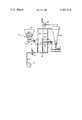
- FIGUREschematically illustrates a preferred embodiment of the present invention.
- a preferred embodiment of the present inventionIn particular, there is disclosed a process for eliminating pollution causing organic material from drill cuttings to enable the drill cuttings to be disposed of directly into the water surrounding an offshore drilling location.
- the inventionmay also be employed on land-based drilling equipment to prevent ecological damage to the earth.
- a conventional drilling derrick with its associated drill worksis mounted on a work platform for drilling a well into the earth formations lying beneath the ocean floor.
- a drill pipe having a drill bit at the lower endis connected to a rotary table and draw works associated with the derrick.
- a mud pitis connected by way of a mud line and mud pump to a mud hose and swivel such that the drilling mud is pumped into the top of the drill pipe down through the length thereof and into the bottom of the borehole through the drill bit.
- a portion of the boreholeis cased with a cement sheath.
- the mudis pumped down through the drill pipe and into the bottom of the borehole. Further pumping of the mud causes it to be pumped up, through the annulus formed between the casing and drill pipe, and into a mud return pipe. As the drill bit cuts into the earth, the drill cuttings or portions of the rock and earth are carried back to the earth's surface via the mud.
- the mudis oil based. Since the mud is used as the transport medium for bringing the drill cuttings to the surface of the borehole, some of the oil from the mud will be entrained in the drill cuttings and adhere to the surface thereof.
- the drill cuttingsthemselves are normally in the form of a slurry, since there is a substantial amount of moisture in the earth cut by the drill bit.
- the combined mud and drill cuttingsare generally pumped to a storage or feed tank for processing.
- screens and/or shale shakersare employed to separate the oil coated, damp, raw cuttings from the mud.
- the drill cuttingsmay then be supplied to a washing screen having a continuous spray of a diesel oil solvent mixture furnished thereto to remove the oil mud adhering to the cuttings.
- other forms of mechanical meanssuch as centrifugal separators, may be employed to separate the cuttings from the mud.
- the drill cuttingsstill have oil entrained therewith.
- the present inventionprovides a process for effectively and efficiently eliminating pollution causing organic material from the drill cuttings.
- Process 10 of the present inventionincludes a feed hopper 12 into which the mechanically clean and washed drill cuttings are conveyed.
- the cuttingsfall by gravity onto a conveying section 14 which preferably comprises an endless chain formed by interconnected screen panels.
- a fan 16delivers a fixed gas, for example air, through a conduit 18 to a heat exchanger 20 functioning as an air heater.
- the temperature of the airis increased through operation of the air heater.
- the air heatermay utilize electricity, hot gas, steam, or other suitable means to increase the temperature of the air passing therethrough.
- the temperature of the airwill be raised to approximately 500° to 550° F. through operation of air heater 20.
- fixed gasrefers to a fluid which is in a gaseous state at standard ambient temperature and pressure conditions.
- a fixed gasshould be contrasted to steam, which at standard conditions, is in its liquid phase.
- steamwhich at standard conditions, is in its liquid phase.
- other fixed gasesmay also be employed, such gases including nitrogen, carbon dioxide, and exhaust gases from internal combustion engines.
- the relatively warm airis discharged from the air heater into conduits 22.
- the airthence passes through the conduits into a heat transfer zone 23 formed in dryer 24.
- dryer 24is a vibrating bed dryer to achieve efficient operation of the present invention.
- Conveyor section 14delivers the drill cuttings through zone 23.
- the airpasses upwardly through the screen panels and then through the drill cuttings disposed thereon.
- the passage of the air at a relatively high velocity, for example 300 feet per minute, plus vibration of the conveying section, through suitable means not shownresults in fluidization of the drill cuttings.
- the individual particles of drill cuttingsare entrained within the flowing air stream. Each particle is completely surrounded by the flowing gas to maximize heat transfer from the gas to the drill cutting particles. Heat from the gas is imparted to the drill cuttings causing moisture and relatively light hydrocarbons to be vaporized and the temperature of the cuttings to be increased.
- the warm temperature gas, passing through heat transfer zone 23is discharged via conduits 26 into a dust collector 30 or similar device.
- the airhas the vaporized hydrocarbons and moisture entrained therewith.
- the gaspasses from the dust collector 30 via an exhaust fan 28 and may thence be delivered to a condenser or similar apparatus if recovery of the entrained vaporous organic material is desired or necessary.
- the relatively clean drill cuttingspass from zone 23 of drying section 24 onto a flatbed 32 from whence the cuttings may be directly disposed of into the surrounding water. The clean cuttings may still have heavier hydrocarbons entrained therewith; however as has been recently recognized, these hydrocarbons are not ecologically harmful.
- the passage of the warm gas through heat transfer zone 23results in two stages of vaporization of the moisture and entrained hydrocarbons from the drill cuttings.
- the fixed gasis very dry and since it is at a relatively warm temperature, its capacity to absorb moisture from the drill cuttings is extremely high.
- the warm temperature gasflows into contact with the fluidized drill cutting particles, the moisture and relatively light hydrocarbons adhering to the surface of the drill cuttings are vaporized therefrom at a constant rate.
- any moisture and hydrocarbons contained in the drill cuttings below the surface thereofwill diffuse to the exterior surface and thence be vaporized by transfer of heat from the gas stream.
- this latter stagesince less heat is required to vaporize the moisture and hydrocarbons, the sensible temperature of the cuttings is increased.
- the individual particles of drill cuttingsare separated and suspended in the gas, resulting in maximum heat transfer between the gas stream and suspended particles.
- the present processemploys a heated fixed gas directly as a heat transfer medium, resulting in direct transfer of heat from the medium to the cuttings.
- a relatively high flow rate of the gas stream through the heat transfer zoneis maintained, for example approximately 300 feet per minute, the removal of moisture and entrained organics from the drill cuttings occurs at a relatively fast rate. In effect, vaporization of the more volatile organics from the drill cuttings will occur at a high rate with a relatively low level of heat input to the fixed gas stream.
- the temperature of the airwill be increased only to 500° to 550° F., the temperature of the drill cuttings will be maintained below the ignition point of the hydrocarbons.
- the foregoingwill enable air to be safely employed without risking combustion of the hydrocarbons.
- a high volume of air flowis maintained resulting in the mixture of air-vaporous organic material being diluted whereby the mixture contains less than 1% organic material. This again will insure that combustion will not be possible with the entrained organics.
- dryersAlthough there are a number of dryers which may be commercially employed in the process of the invention, one such dryer is manufactured by the Jeffrey Manufacturing division of Dresser Industries, Inc. and is illustrated in "Jeffrey" catalog 1149-3.5 entitled “Dryers and Coolers.”
- the above described processprovides an efficient and effective means for eliminating pollution causing hydrocarbons from drill cuttings permitting the subsequent disposal thereof into water surrounding an offshore drilling site.
Landscapes
- Engineering & Computer Science (AREA)
- Life Sciences & Earth Sciences (AREA)
- Mining & Mineral Resources (AREA)
- Geology (AREA)
- Environmental & Geological Engineering (AREA)
- Mechanical Engineering (AREA)
- Physics & Mathematics (AREA)
- Fluid Mechanics (AREA)
- General Life Sciences & Earth Sciences (AREA)
- Geochemistry & Mineralogy (AREA)
- General Engineering & Computer Science (AREA)
- Microbiology (AREA)
- Earth Drilling (AREA)
- Drying Of Solid Materials (AREA)
- Manufacture And Refinement Of Metals (AREA)
Abstract
Description
Claims (6)
Priority Applications (5)
| Application Number | Priority Date | Filing Date | Title |
|---|---|---|---|
| US06/251,437US4387514A (en) | 1981-04-06 | 1981-04-06 | Method for drying oil well drill cuttings |
| CA000398674ACA1178048A (en) | 1981-04-06 | 1982-03-17 | Method for drying oil well drill cuttings |
| NL8201348ANL8201348A (en) | 1981-04-06 | 1982-03-31 | METHOD FOR DRYING DRILLING CROSS FROM A DRILLING WELL |
| GB8209720AGB2096297A (en) | 1981-04-06 | 1982-04-01 | Method for drying well drill cuttings |
| NO821119ANO821119L (en) | 1981-04-06 | 1982-04-02 | PROCEDURE FOR DRYING DRILL CAKES FROM OIL BROWN |
Applications Claiming Priority (1)
| Application Number | Priority Date | Filing Date | Title |
|---|---|---|---|
| US06/251,437US4387514A (en) | 1981-04-06 | 1981-04-06 | Method for drying oil well drill cuttings |
Publications (1)
| Publication Number | Publication Date |
|---|---|
| US4387514Atrue US4387514A (en) | 1983-06-14 |
Family
ID=22951967
Family Applications (1)
| Application Number | Title | Priority Date | Filing Date |
|---|---|---|---|
| US06/251,437Expired - Fee RelatedUS4387514A (en) | 1981-04-06 | 1981-04-06 | Method for drying oil well drill cuttings |
Country Status (5)
| Country | Link |
|---|---|
| US (1) | US4387514A (en) |
| CA (1) | CA1178048A (en) |
| GB (1) | GB2096297A (en) |
| NL (1) | NL8201348A (en) |
| NO (1) | NO821119L (en) |
Cited By (21)
| Publication number | Priority date | Publication date | Assignee | Title |
|---|---|---|---|---|
| US4683963A (en)* | 1985-04-19 | 1987-08-04 | Atlantic Richfield Company | Drilling cuttings treatment |
| US4839022A (en)* | 1984-12-03 | 1989-06-13 | Atlantic Richfield Company | Method and apparatus for treating oil-water-solids sludges and refinery waste streams |
| US4872949A (en)* | 1988-03-08 | 1989-10-10 | Wilwerding Carl M | Process for treatment of drilling mud |
| US4913245A (en)* | 1984-12-03 | 1990-04-03 | Atlantic Richfield Company | Wellbore drilling cuttings treatment |
| USH1000H (en) | 1990-03-30 | 1991-12-03 | M-I Drilling Fluids Company | Water based synthetic hydrocarbon drilling fluid and spotting fluid |
| US5090498A (en)* | 1989-11-10 | 1992-02-25 | M-I Drilling Fluids Company | Water wash/oil wash cyclonic column tank separation system |
| US5707939A (en)* | 1995-09-21 | 1998-01-13 | M-I Drilling Fluids | Silicone oil-based drilling fluids |
| WO2000049269A1 (en)* | 1999-02-17 | 2000-08-24 | Mcintyre Barry E | Method and apparatus for cleaning drill cuttings |
| US6440312B1 (en)* | 2000-05-02 | 2002-08-27 | Kai Technologies, Inc. | Extracting oil and water from drill cuttings using RF energy |
| US20020153288A1 (en)* | 2001-04-18 | 2002-10-24 | M-I L.L.C. | Motor control system for vibrating screen separator |
| WO2002085491A1 (en) | 2001-04-18 | 2002-10-31 | M-I L.L.C. | Flow diverter and exhaust blower for a vibrating screen separator assembly |
| WO2004011767A1 (en)* | 2002-07-25 | 2004-02-05 | Martin Mckenzie | Apparatus and method for transporting of drill cuttings |
| WO2005054623A1 (en)* | 2003-12-01 | 2005-06-16 | Clean Cut Technologies Inc. | An apparatus and process for removing liquids from drill cuttings |
| US20060185236A1 (en)* | 2003-08-20 | 2006-08-24 | Hill Houston E | Method and apparatus for converting spent water-based drilling muds into fertile indigenous top soil |
| US7373996B1 (en) | 2002-12-17 | 2008-05-20 | Centrifugal Services, Inc. | Method and system for separation of drilling/production fluids and drilled earthen solids |
| CN100404989C (en)* | 2002-12-18 | 2008-07-23 | 兰州瑞德干燥技术有限公司 | A kind of engineering plastic air flow and fluidized bed drying method with nitrogen circulation |
| US20100146814A1 (en)* | 2008-12-11 | 2010-06-17 | Baker Stephen T | Vibratory Flash Dryer |
| US20150204151A1 (en)* | 2010-03-18 | 2015-07-23 | Daniel Guy Pomerleau | Optimization Of Vacuum System And Methods For Drying Drill Cuttings |
| WO2020236226A1 (en)* | 2019-05-23 | 2020-11-26 | Halliburton Energy Services, Inc. | Thermal desorption of oily solids |
| EP4062024A4 (en)* | 2019-11-22 | 2023-03-15 | Elavo Energy Solutions Ltd. | SYSTEM AND PROCESS FOR REMOVAL OF DRILLING FLUID FROM DRILLINGS USING DIRECT HEAT |
| US12098602B2 (en) | 2019-11-22 | 2024-09-24 | Elavo Cleantech Ltd. | System and method for removing drilling fluid from drill cuttings using direct heat |
Families Citing this family (4)
| Publication number | Priority date | Publication date | Assignee | Title |
|---|---|---|---|---|
| NO167710C (en)* | 1984-12-03 | 1991-12-04 | Atlantic Richfield Co | PROCEDURE FOR RECOVERY OF MAIN DRY, OIL FREE, SOLID PARTICLES. |
| JPS63256200A (en)* | 1987-04-02 | 1988-10-24 | ヘイドン・シュワイツァ−・コ−ポレ−ション | Processing method and equipment for organic and inorganic mixed waste |
| AU2003201416A1 (en) | 2002-01-03 | 2003-07-15 | Hood Environmental Engineering Ltd. | Thermal remediation process |
| DK3231984T3 (en)* | 2016-04-11 | 2020-08-31 | Max Wild Gmbh | PROCEDURE FOR TREATING DRILLING SLUDGE |
Citations (7)
| Publication number | Priority date | Publication date | Assignee | Title |
|---|---|---|---|---|
| US3658015A (en)* | 1970-04-15 | 1972-04-25 | Dresser Ind | Explosive-proof method and incinerator for burning drill cuttings |
| US3693951A (en)* | 1970-12-30 | 1972-09-26 | Nl Industries Inc | Process and apparatus for the treatment of well cuttings |
| US3768174A (en)* | 1971-04-19 | 1973-10-30 | Escher Wyss Ag | Fluidised bed device |
| US4058905A (en)* | 1974-12-19 | 1977-11-22 | The Superior Oil Company | Method for reducing residence time and eliminating gas leakage between zones in a cross-flow device for heating and cooling solids |
| US4139462A (en)* | 1976-07-12 | 1979-02-13 | Dresser Industries, Inc. | Method for thermally treating oil well drill cuttings |
| US4209381A (en)* | 1978-02-02 | 1980-06-24 | Mobil Oil Corporation | Method and apparatus for treating drill cuttings at an onsite location |
| US4222988A (en)* | 1978-05-05 | 1980-09-16 | Oil Base Germany G.M.B.H. | Apparatus for removing hydrocarbons from drill cuttings |
- 1981
- 1981-04-06USUS06/251,437patent/US4387514A/ennot_activeExpired - Fee Related
- 1982
- 1982-03-17CACA000398674Apatent/CA1178048A/ennot_activeExpired
- 1982-03-31NLNL8201348Apatent/NL8201348A/ennot_activeApplication Discontinuation
- 1982-04-01GBGB8209720Apatent/GB2096297A/ennot_activeWithdrawn
- 1982-04-02NONO821119Apatent/NO821119L/enunknown
Patent Citations (8)
| Publication number | Priority date | Publication date | Assignee | Title |
|---|---|---|---|---|
| US3658015A (en)* | 1970-04-15 | 1972-04-25 | Dresser Ind | Explosive-proof method and incinerator for burning drill cuttings |
| US3693951A (en)* | 1970-12-30 | 1972-09-26 | Nl Industries Inc | Process and apparatus for the treatment of well cuttings |
| US3768174A (en)* | 1971-04-19 | 1973-10-30 | Escher Wyss Ag | Fluidised bed device |
| US4058905A (en)* | 1974-12-19 | 1977-11-22 | The Superior Oil Company | Method for reducing residence time and eliminating gas leakage between zones in a cross-flow device for heating and cooling solids |
| US4139462A (en)* | 1976-07-12 | 1979-02-13 | Dresser Industries, Inc. | Method for thermally treating oil well drill cuttings |
| US4208285A (en)* | 1976-07-12 | 1980-06-17 | Dresser Industries, Inc. | Drill cuttings disposal system with good environmental and ecological properties |
| US4209381A (en)* | 1978-02-02 | 1980-06-24 | Mobil Oil Corporation | Method and apparatus for treating drill cuttings at an onsite location |
| US4222988A (en)* | 1978-05-05 | 1980-09-16 | Oil Base Germany G.M.B.H. | Apparatus for removing hydrocarbons from drill cuttings |
Non-Patent Citations (2)
| Title |
|---|
| "Is Oil a Threat to Marine EcoSystems?", Houston Engineer, Jun. 1980.* |
| Catalog 1149-3.5 "Dryers and Coolers".* |
Cited By (49)
| Publication number | Priority date | Publication date | Assignee | Title |
|---|---|---|---|---|
| US4839022A (en)* | 1984-12-03 | 1989-06-13 | Atlantic Richfield Company | Method and apparatus for treating oil-water-solids sludges and refinery waste streams |
| US4913245A (en)* | 1984-12-03 | 1990-04-03 | Atlantic Richfield Company | Wellbore drilling cuttings treatment |
| US4683963A (en)* | 1985-04-19 | 1987-08-04 | Atlantic Richfield Company | Drilling cuttings treatment |
| US4872949A (en)* | 1988-03-08 | 1989-10-10 | Wilwerding Carl M | Process for treatment of drilling mud |
| US5090498A (en)* | 1989-11-10 | 1992-02-25 | M-I Drilling Fluids Company | Water wash/oil wash cyclonic column tank separation system |
| USH1000H (en) | 1990-03-30 | 1991-12-03 | M-I Drilling Fluids Company | Water based synthetic hydrocarbon drilling fluid and spotting fluid |
| US5189012A (en)* | 1990-03-30 | 1993-02-23 | M-I Drilling Fluids Company | Oil based synthetic hydrocarbon drilling fluid |
| EP0764711A2 (en) | 1990-03-30 | 1997-03-26 | M-I Drilling Fluids Company | Oil based synthetic hydrocarbon drilling fluid |
| US5707939A (en)* | 1995-09-21 | 1998-01-13 | M-I Drilling Fluids | Silicone oil-based drilling fluids |
| US6530438B1 (en)* | 1999-02-17 | 2003-03-11 | Mcintyre Barry E. | Apparatus and process for removing drilling fluid from drill cuttings |
| WO2000049269A1 (en)* | 1999-02-17 | 2000-08-24 | Mcintyre Barry E | Method and apparatus for cleaning drill cuttings |
| US6440312B1 (en)* | 2000-05-02 | 2002-08-27 | Kai Technologies, Inc. | Extracting oil and water from drill cuttings using RF energy |
| WO2002085491A1 (en) | 2001-04-18 | 2002-10-31 | M-I L.L.C. | Flow diverter and exhaust blower for a vibrating screen separator assembly |
| US20040251182A1 (en)* | 2001-04-18 | 2004-12-16 | M-I L.L.C. | Flow diverter and exhaust blower for vibrating screen separator assembly |
| US20030024398A1 (en)* | 2001-04-18 | 2003-02-06 | M-I L.L.C. | Flow diverter and exhaust blower for vibrating screen separator assembly |
| AU2002258654B2 (en)* | 2001-04-18 | 2007-08-30 | M-I L.L.C. | Flow diverter and exhaust blower for a vibrating screen separator assembly |
| US6679385B2 (en) | 2001-04-18 | 2004-01-20 | M I Llc. | Motor control system for vibrating screen separator |
| US7380672B2 (en) | 2001-04-18 | 2008-06-03 | M-I L.L.C. | Flow diverter and exhaust blower for vibrating screen separator assembly |
| US6746602B2 (en) | 2001-04-18 | 2004-06-08 | M-I L.L.C. | Flow diverter and exhaust blower for vibrating screen separator assembly |
| US6485640B2 (en)* | 2001-04-18 | 2002-11-26 | Gary Fout | Flow diverter and exhaust blower for vibrating screen separator assembly |
| US6838008B2 (en) | 2001-04-18 | 2005-01-04 | M-I Llc | Flow diverter and exhaust blower for vibrating screen separator assembly |
| US20050087501A1 (en)* | 2001-04-18 | 2005-04-28 | M-I L.L.C. | Flow diverter and exhaust blower for vibrating screen separator assembly |
| US20020153288A1 (en)* | 2001-04-18 | 2002-10-24 | M-I L.L.C. | Motor control system for vibrating screen separator |
| US7380673B2 (en) | 2001-04-18 | 2008-06-03 | M-I L.L.C. | Flow diverter and exhaust blower for vibrating screen separator assembly |
| WO2004011767A1 (en)* | 2002-07-25 | 2004-02-05 | Martin Mckenzie | Apparatus and method for transporting of drill cuttings |
| US7373996B1 (en) | 2002-12-17 | 2008-05-20 | Centrifugal Services, Inc. | Method and system for separation of drilling/production fluids and drilled earthen solids |
| CN100404989C (en)* | 2002-12-18 | 2008-07-23 | 兰州瑞德干燥技术有限公司 | A kind of engineering plastic air flow and fluidized bed drying method with nitrogen circulation |
| US20060185236A1 (en)* | 2003-08-20 | 2006-08-24 | Hill Houston E | Method and apparatus for converting spent water-based drilling muds into fertile indigenous top soil |
| US20070214715A1 (en)* | 2003-08-20 | 2007-09-20 | Hill Houston E | Method and apparatus for converting spent water-based drilling muds into fertile indigenous top soil |
| US7272912B2 (en)* | 2003-08-20 | 2007-09-25 | Hill Houston E | Method and apparatus for converting spent water-based drilling muds into fertile indigenous top soil |
| US7322152B2 (en) | 2003-08-20 | 2008-01-29 | Hill Houston E | Method and apparatus for converting spent water-based drilling muds into fertile indigenous top soil |
| US20070107303A1 (en)* | 2003-08-20 | 2007-05-17 | Hill Houston E | Method and apparatus for converting spent water-based drilling muds into fertile indigenous top soil |
| US20060191195A1 (en)* | 2003-08-20 | 2006-08-31 | Hill Houston E | Method and apparatus for converting spent water-based drilling muds into fertile indigenous top soil |
| US7444780B2 (en) | 2003-08-20 | 2008-11-04 | Hill Houston E | Method and apparatus for converting spent water-based drilling muds into fertile indigenous top soil |
| US7337860B2 (en)* | 2003-12-01 | 2008-03-04 | Clean Cut Technologies Inc. | Apparatus and process for removing liquids from drill cuttings |
| US20050153844A1 (en)* | 2003-12-01 | 2005-07-14 | Mcintyre Barry E. | Apparatus and process for removing liquids from drill cuttings |
| WO2005054623A1 (en)* | 2003-12-01 | 2005-06-16 | Clean Cut Technologies Inc. | An apparatus and process for removing liquids from drill cuttings |
| EP2196757A3 (en)* | 2008-12-11 | 2011-06-08 | Carrier Vibrating Equipment, Inc. | Vibratory flash dryer |
| US20100146814A1 (en)* | 2008-12-11 | 2010-06-17 | Baker Stephen T | Vibratory Flash Dryer |
| US20170067686A1 (en)* | 2008-12-11 | 2017-03-09 | Carrier Vibrating Equipment, Inc. | Vibratory Flash Dryer |
| US20150204151A1 (en)* | 2010-03-18 | 2015-07-23 | Daniel Guy Pomerleau | Optimization Of Vacuum System And Methods For Drying Drill Cuttings |
| US10335720B2 (en) | 2010-03-18 | 2019-07-02 | Fp Marangoni Inc. | Optimization of vacuum system and methods for drying drill cuttings |
| WO2020236226A1 (en)* | 2019-05-23 | 2020-11-26 | Halliburton Energy Services, Inc. | Thermal desorption of oily solids |
| GB2596018A (en)* | 2019-05-23 | 2021-12-15 | Halliburton Energy Services Inc | Thermal desorption of oily solids |
| US11219842B2 (en) | 2019-05-23 | 2022-01-11 | Halliburton Energy Services, Inc. | Thermal desorption of oily solids |
| GB2596018B (en)* | 2019-05-23 | 2023-08-02 | Halliburton Energy Services Inc | Thermal desorption of oily solids |
| EP4062024A4 (en)* | 2019-11-22 | 2023-03-15 | Elavo Energy Solutions Ltd. | SYSTEM AND PROCESS FOR REMOVAL OF DRILLING FLUID FROM DRILLINGS USING DIRECT HEAT |
| US11970917B2 (en) | 2019-11-22 | 2024-04-30 | Elavo Energy Solutions Ltd. | System and method for removing drilling fluid from drill cuttings using direct heat |
| US12098602B2 (en) | 2019-11-22 | 2024-09-24 | Elavo Cleantech Ltd. | System and method for removing drilling fluid from drill cuttings using direct heat |
Also Published As
| Publication number | Publication date |
|---|---|
| CA1178048A (en) | 1984-11-20 |
| NO821119L (en) | 1982-10-07 |
| GB2096297A (en) | 1982-10-13 |
| NL8201348A (en) | 1982-11-01 |
Similar Documents
| Publication | Publication Date | Title |
|---|---|---|
| US4387514A (en) | Method for drying oil well drill cuttings | |
| US4139462A (en) | Method for thermally treating oil well drill cuttings | |
| US4725362A (en) | Treatment techniques for drill fluids, cuttings and other oil field wastes | |
| US4136747A (en) | Method and means for reduction of oxygen content in drilling fluid | |
| US4751887A (en) | Treatment of oil field wastes | |
| US5090498A (en) | Water wash/oil wash cyclonic column tank separation system | |
| US4836302A (en) | Apparatus and method for removing and recovering oil and/or other oil-based drilling mud additives from drill cuttings | |
| WO2020052109A1 (en) | Rotational flow rotation deoiling method and device for oil-based mud rock debris | |
| US4209381A (en) | Method and apparatus for treating drill cuttings at an onsite location | |
| US3693951A (en) | Process and apparatus for the treatment of well cuttings | |
| NO335027B1 (en) | Method and apparatus for cleaning cuttings | |
| CA2473256A1 (en) | Soil cleaning systems and methods | |
| CN108251148A (en) | A kind of dangerous waste, solid waste oil-containing mud sand Thermal desorption comprehensive utilization method of disposal | |
| US4350505A (en) | Device for reduction of oxygen content in drilling fluid | |
| CN109045770A (en) | For the oil-base mud landwaste processing method of marine drilling platform and with boring device | |
| CN111661995A (en) | Oil-based drilling waste recycling and harmless treatment system and method | |
| US4313785A (en) | Method and apparatus for treating waste rock cuttings | |
| US20030037922A1 (en) | System and method for processing oil-based mud cuttings | |
| WO2021097565A1 (en) | System and method for removing drilling fluid from drill cuttings using direct heat | |
| CN109267953B (en) | Method and device for grading recovery of mud and base oil in waste oil-based drilling fluid | |
| US20170023247A1 (en) | System and method for treating waste particulate solids | |
| US3570420A (en) | Process for the removal of hydrocarbons contained in earth cuttings from subterranean wells | |
| CN109184601A (en) | Discarded oil base drilling fluid cyclone gas drives away oily method and apparatus | |
| CN100523689C (en) | Drill cuttings treatment method and apparatus | |
| CN109020123B (en) | Method and device for non-falling circulation of oil-bearing solid pollutants in onshore oil and gas fields |
Legal Events
| Date | Code | Title | Description |
|---|---|---|---|
| AS | Assignment | Owner name:DRESSER INDUSTRIES, INC., DALLAS, TEX. A CORP. OF Free format text:ASSIGNMENT OF ASSIGNORS INTEREST.;ASSIGNOR:MC CASKILL JAMES N. JR.;REEL/FRAME:003883/0434 Effective date:19810403 Owner name:DRESSER INDUSTRIES, INC., A CORP. OF DE., TEXAS Free format text:ASSIGNMENT OF ASSIGNORS INTEREST;ASSIGNOR:MC CASKILL JAMES N. JR.;REEL/FRAME:003883/0434 Effective date:19810403 | |
| FEPP | Fee payment procedure | Free format text:MAINTENANCE FEE REMINDER MAILED (ORIGINAL EVENT CODE: REM.); ENTITY STATUS OF PATENT OWNER: LARGE ENTITY | |
| FEPP | Fee payment procedure | Free format text:SURCHARGE FOR LATE PAYMENT, PL 96-517 (ORIGINAL EVENT CODE: M176); ENTITY STATUS OF PATENT OWNER: LARGE ENTITY | |
| MAFP | Maintenance fee payment | Free format text:PAYMENT OF MAINTENANCE FEE, 4TH YEAR, PL 96-517 (ORIGINAL EVENT CODE: M170); ENTITY STATUS OF PATENT OWNER: LARGE ENTITY Year of fee payment:4 | |
| AS | Assignment | Owner name:MI DRILLING FLUIDS COMPANY, HOUSTON, TX., A TX. GE Free format text:ASSIGNMENT OF ASSIGNORS INTEREST. EFFECTIVE DEC. 1, 1986,;ASSIGNOR:DRESSER INDUSTRIES, INC., A CORP OF DE.;REEL/FRAME:004669/0784 Effective date:19870205 Owner name:MI DRILLING FLUIDS COMPANY, A TX. GENERAL PARTNERS Free format text:ASSIGNMENT OF ASSIGNORS INTEREST;ASSIGNOR:DRESSER INDUSTRIES, INC., A CORP OF DE.;REEL/FRAME:004669/0784 Effective date:19870205 | |
| FEPP | Fee payment procedure | Free format text:MAINTENANCE FEE REMINDER MAILED (ORIGINAL EVENT CODE: REM.); ENTITY STATUS OF PATENT OWNER: LARGE ENTITY | |
| LAPS | Lapse for failure to pay maintenance fees | ||
| STCH | Information on status: patent discontinuation | Free format text:PATENT EXPIRED DUE TO NONPAYMENT OF MAINTENANCE FEES UNDER 37 CFR 1.362 | |
| FP | Lapsed due to failure to pay maintenance fee | Effective date:19910616 |