US4386501A - Heat pump using liquid ammoniated ammonium chloride, and thermal storage system - Google Patents
Heat pump using liquid ammoniated ammonium chloride, and thermal storage systemDownload PDFInfo
- Publication number
- US4386501A US4386501AUS06/287,992US28799281AUS4386501AUS 4386501 AUS4386501 AUS 4386501AUS 28799281 AUS28799281 AUS 28799281AUS 4386501 AUS4386501 AUS 4386501A
- Authority
- US
- United States
- Prior art keywords
- ammonia
- ammoniate
- heat
- ammonium chloride
- low
- Prior art date
- Legal status (The legal status is an assumption and is not a legal conclusion. Google has not performed a legal analysis and makes no representation as to the accuracy of the status listed.)
- Expired - Fee Related
Links
- NLXLAEXVIDQMFP-UHFFFAOYSA-NAmmonia chlorideChemical compound[NH4+].[Cl-]NLXLAEXVIDQMFP-UHFFFAOYSA-N0.000titleclaimsabstractdescription66
- 235000019270ammonium chlorideNutrition0.000titleclaimsabstractdescription33
- 239000007788liquidSubstances0.000titleclaimsabstractdescription19
- QGZKDVFQNNGYKY-UHFFFAOYSA-NAmmoniaChemical compoundNQGZKDVFQNNGYKY-UHFFFAOYSA-N0.000claimsabstractdescription209
- 229910021529ammoniaInorganic materials0.000claimsabstractdescription99
- 238000001816coolingMethods0.000claimsabstractdescription30
- 238000010438heat treatmentMethods0.000claimsabstractdescription26
- 238000005057refrigerationMethods0.000claimsabstractdescription23
- 230000002745absorbentEffects0.000claimsabstractdescription17
- 239000002250absorbentSubstances0.000claimsabstractdescription17
- 238000000034methodMethods0.000claimsabstractdescription16
- 239000002699waste materialSubstances0.000claimsabstractdescription4
- 239000006096absorbing agentSubstances0.000claimsdescription27
- 229910017917NH4 ClInorganic materials0.000claimsdescription7
- 238000003795desorptionMethods0.000claimsdescription7
- 229910000069nitrogen hydrideInorganic materials0.000claimsdescription3
- 150000003839saltsChemical class0.000abstractdescription9
- 239000000126substanceSubstances0.000abstractdescription2
- 238000004146energy storageMethods0.000abstract2
- 239000012530fluidSubstances0.000description34
- 239000003570airSubstances0.000description22
- 238000010521absorption reactionMethods0.000description12
- 239000013529heat transfer fluidSubstances0.000description10
- 239000012080ambient airSubstances0.000description9
- XLYOFNOQVPJJNP-UHFFFAOYSA-NwaterSubstancesOXLYOFNOQVPJJNP-UHFFFAOYSA-N0.000description9
- 238000006243chemical reactionMethods0.000description5
- 239000000498cooling waterSubstances0.000description5
- 239000003507refrigerantSubstances0.000description5
- VHUUQVKOLVNVRT-UHFFFAOYSA-NAmmonium hydroxideChemical compound[NH4+].[OH-]VHUUQVKOLVNVRT-UHFFFAOYSA-N0.000description4
- VEXZGXHMUGYJMC-UHFFFAOYSA-MChloride anionChemical compound[Cl-]VEXZGXHMUGYJMC-UHFFFAOYSA-M0.000description4
- 235000011114ammonium hydroxideNutrition0.000description4
- 239000007795chemical reaction productSubstances0.000description4
- 230000001143conditioned effectEffects0.000description4
- 238000005086pumpingMethods0.000description4
- YMWUJEATGCHHMB-UHFFFAOYSA-NDichloromethaneChemical compoundClCClYMWUJEATGCHHMB-UHFFFAOYSA-N0.000description3
- 239000000203mixtureSubstances0.000description3
- 239000003921oilSubstances0.000description3
- 238000009834vaporizationMethods0.000description3
- 230000008016vaporizationEffects0.000description3
- BAVYZALUXZFZLV-UHFFFAOYSA-NMethylamineChemical compoundNCBAVYZALUXZFZLV-UHFFFAOYSA-N0.000description2
- 238000009835boilingMethods0.000description2
- 150000001805chlorine compoundsChemical class0.000description2
- 230000000694effectsEffects0.000description2
- 239000007787solidSubstances0.000description2
- MHCVCKDNQYMGEX-UHFFFAOYSA-N1,1'-biphenyl;phenoxybenzeneChemical compoundC1=CC=CC=C1C1=CC=CC=C1.C=1C=CC=CC=1OC1=CC=CC=C1MHCVCKDNQYMGEX-UHFFFAOYSA-N0.000description1
- CPELXLSAUQHCOX-UHFFFAOYSA-MBromideChemical compound[Br-]CPELXLSAUQHCOX-UHFFFAOYSA-M0.000description1
- WHXSMMKQMYFTQS-UHFFFAOYSA-NLithiumChemical compound[Li]WHXSMMKQMYFTQS-UHFFFAOYSA-N0.000description1
- 229910002651NO3Inorganic materials0.000description1
- NHNBFGGVMKEFGY-UHFFFAOYSA-NNitrateChemical compound[O-][N+]([O-])=ONHNBFGGVMKEFGY-UHFFFAOYSA-N0.000description1
- 229910052784alkaline earth metalInorganic materials0.000description1
- 150000001342alkaline earth metalsChemical class0.000description1
- DVARTQFDIMZBAA-UHFFFAOYSA-Oammonium nitrateChemical class[NH4+].[O-][N+]([O-])=ODVARTQFDIMZBAA-UHFFFAOYSA-O0.000description1
- 150000003863ammonium saltsChemical class0.000description1
- 230000009286beneficial effectEffects0.000description1
- 238000004891communicationMethods0.000description1
- 238000009833condensationMethods0.000description1
- 230000005494condensationEffects0.000description1
- 238000007599dischargingMethods0.000description1
- 238000001704evaporationMethods0.000description1
- 230000008020evaporationEffects0.000description1
- 230000007717exclusionEffects0.000description1
- 150000002334glycolsChemical class0.000description1
- 150000004820halidesChemical class0.000description1
- 238000005338heat storageMethods0.000description1
- XMBWDFGMSWQBCA-UHFFFAOYSA-Nhydrogen iodideChemical compoundIXMBWDFGMSWQBCA-UHFFFAOYSA-N0.000description1
- 239000007791liquid phaseSubstances0.000description1
- 229910052744lithiumInorganic materials0.000description1
- IPLONMMJNGTUAI-UHFFFAOYSA-Mlithium;bromide;hydrateChemical compound[Li+].O.[Br-]IPLONMMJNGTUAI-UHFFFAOYSA-M0.000description1
- 239000000463materialSubstances0.000description1
- 150000002823nitratesChemical class0.000description1
- 230000009972noncorrosive effectEffects0.000description1
- 231100000252nontoxicToxicity0.000description1
- 230000003000nontoxic effectEffects0.000description1
- 239000003208petroleumSubstances0.000description1
- 230000000704physical effectEffects0.000description1
- 229920000151polyglycolPolymers0.000description1
- 239000010695polyglycolSubstances0.000description1
- VGTPCRGMBIAPIM-UHFFFAOYSA-Msodium thiocyanateChemical compound[Na+].[S-]C#NVGTPCRGMBIAPIM-UHFFFAOYSA-M0.000description1
- 239000002351wastewaterSubstances0.000description1
Images


Classifications
- F—MECHANICAL ENGINEERING; LIGHTING; HEATING; WEAPONS; BLASTING
- F25—REFRIGERATION OR COOLING; COMBINED HEATING AND REFRIGERATION SYSTEMS; HEAT PUMP SYSTEMS; MANUFACTURE OR STORAGE OF ICE; LIQUEFACTION SOLIDIFICATION OF GASES
- F25B—REFRIGERATION MACHINES, PLANTS OR SYSTEMS; COMBINED HEATING AND REFRIGERATION SYSTEMS; HEAT PUMP SYSTEMS
- F25B15/00—Sorption machines, plants or systems, operating continuously, e.g. absorption type
- F—MECHANICAL ENGINEERING; LIGHTING; HEATING; WEAPONS; BLASTING
- F25—REFRIGERATION OR COOLING; COMBINED HEATING AND REFRIGERATION SYSTEMS; HEAT PUMP SYSTEMS; MANUFACTURE OR STORAGE OF ICE; LIQUEFACTION SOLIDIFICATION OF GASES
- F25B—REFRIGERATION MACHINES, PLANTS OR SYSTEMS; COMBINED HEATING AND REFRIGERATION SYSTEMS; HEAT PUMP SYSTEMS
- F25B30/00—Heat pumps
- F25B30/04—Heat pumps of the sorption type
- F—MECHANICAL ENGINEERING; LIGHTING; HEATING; WEAPONS; BLASTING
- F28—HEAT EXCHANGE IN GENERAL
- F28D—HEAT-EXCHANGE APPARATUS, NOT PROVIDED FOR IN ANOTHER SUBCLASS, IN WHICH THE HEAT-EXCHANGE MEDIA DO NOT COME INTO DIRECT CONTACT
- F28D20/00—Heat storage plants or apparatus in general; Regenerative heat-exchange apparatus not covered by groups F28D17/00 or F28D19/00
- F28D20/003—Heat storage plants or apparatus in general; Regenerative heat-exchange apparatus not covered by groups F28D17/00 or F28D19/00 using thermochemical reactions
- Y—GENERAL TAGGING OF NEW TECHNOLOGICAL DEVELOPMENTS; GENERAL TAGGING OF CROSS-SECTIONAL TECHNOLOGIES SPANNING OVER SEVERAL SECTIONS OF THE IPC; TECHNICAL SUBJECTS COVERED BY FORMER USPC CROSS-REFERENCE ART COLLECTIONS [XRACs] AND DIGESTS
- Y02—TECHNOLOGIES OR APPLICATIONS FOR MITIGATION OR ADAPTATION AGAINST CLIMATE CHANGE
- Y02A—TECHNOLOGIES FOR ADAPTATION TO CLIMATE CHANGE
- Y02A30/00—Adapting or protecting infrastructure or their operation
- Y02A30/27—Relating to heating, ventilation or air conditioning [HVAC] technologies
- Y—GENERAL TAGGING OF NEW TECHNOLOGICAL DEVELOPMENTS; GENERAL TAGGING OF CROSS-SECTIONAL TECHNOLOGIES SPANNING OVER SEVERAL SECTIONS OF THE IPC; TECHNICAL SUBJECTS COVERED BY FORMER USPC CROSS-REFERENCE ART COLLECTIONS [XRACs] AND DIGESTS
- Y02—TECHNOLOGIES OR APPLICATIONS FOR MITIGATION OR ADAPTATION AGAINST CLIMATE CHANGE
- Y02B—CLIMATE CHANGE MITIGATION TECHNOLOGIES RELATED TO BUILDINGS, e.g. HOUSING, HOUSE APPLIANCES OR RELATED END-USER APPLICATIONS
- Y02B30/00—Energy efficient heating, ventilation or air conditioning [HVAC]
- Y02B30/62—Absorption based systems
- Y—GENERAL TAGGING OF NEW TECHNOLOGICAL DEVELOPMENTS; GENERAL TAGGING OF CROSS-SECTIONAL TECHNOLOGIES SPANNING OVER SEVERAL SECTIONS OF THE IPC; TECHNICAL SUBJECTS COVERED BY FORMER USPC CROSS-REFERENCE ART COLLECTIONS [XRACs] AND DIGESTS
- Y02—TECHNOLOGIES OR APPLICATIONS FOR MITIGATION OR ADAPTATION AGAINST CLIMATE CHANGE
- Y02E—REDUCTION OF GREENHOUSE GAS [GHG] EMISSIONS, RELATED TO ENERGY GENERATION, TRANSMISSION OR DISTRIBUTION
- Y02E60/00—Enabling technologies; Technologies with a potential or indirect contribution to GHG emissions mitigation
- Y02E60/14—Thermal energy storage
- Y—GENERAL TAGGING OF NEW TECHNOLOGICAL DEVELOPMENTS; GENERAL TAGGING OF CROSS-SECTIONAL TECHNOLOGIES SPANNING OVER SEVERAL SECTIONS OF THE IPC; TECHNICAL SUBJECTS COVERED BY FORMER USPC CROSS-REFERENCE ART COLLECTIONS [XRACs] AND DIGESTS
- Y02—TECHNOLOGIES OR APPLICATIONS FOR MITIGATION OR ADAPTATION AGAINST CLIMATE CHANGE
- Y02E—REDUCTION OF GREENHOUSE GAS [GHG] EMISSIONS, RELATED TO ENERGY GENERATION, TRANSMISSION OR DISTRIBUTION
- Y02E70/00—Other energy conversion or management systems reducing GHG emissions
- Y02E70/30—Systems combining energy storage with energy generation of non-fossil origin
Definitions
- Heat pumpsare widely used for heating and cooling buildings primarily in moderate climates.
- Such heat pumpsgenerally include a refrigeration system having a condenser exposed to ambient conditions and an evaporator exposed to the enclosure, house or other zone to be air conditioned so as to provide cooling for the zone.
- suitable meansgenerally including flow control valves, are provided to transfer heat required for the evaporation portion of the process to the ambient surroundings, and to transfer heat generated by the condenser portion of the process to the zone.
- This inventionrelates to a working fluid and, to a process specifically designed to include a heat pump system to provide, optionally, heat and/or refrigeration by suitable heat exchange, using operations that include vaporization, expansion, and condensation of a chemically and thermally stable refrigerant which is alternately absorbed and desorbed from the working fluid without using a compressor. More particularly, the invention relates to a heat pump based on an absorption system which uses an improved working fluid, and the heat pump may be used either continuously or in a cyclical (that is, "batch-type") operation, depending upon the work it is to perform.
- the working fluidis a liquid ammoniate formed by ammoniating ammonium chloride to form a reaction product or complex (hereafter "complex" for brevity) of ammonia with the ammonium chloride, and is not a simple physical solution of the chloride in ammonia, but chemically combined with it.
- the working fluidis the complex containing no more ammonia than is effective to make the absorbent a pumpable liquid, in which state the absorbent is therefore referred to as a "low ammoniate”.
- the working fluidbecomes a highly ammoniated complex (hence referred to as "high ammoniate") which is to be desorbed in the generator.
- U.S. Pat. No. 2,986,525 to Hughesdiscloses the use of anhydrous mixtures of the halides of the alkaline earth metals and various nitrates and chlorides such as lithium and ammonium nitrates or chlorides to form a strong porous mass for absorption of ammonia when the mass is cooled, and desorption of the ammonia when the mass is heated.
- the saltsone of which may be ammonium chloride, are fused and intimately blended together to form a "eutectoid".
- ammonium chlorideis essentially insoluble in a complex of ammonium chloride and ammonia
- a complex formed by approximately equimolar quantities of ammonium chloride and ammoniawould provide a pumpable liquid especially well-adapted for use as the absorbent in a continuously or cyclically operable heat pump in which the energy is provided by a heat source below 100° C.
- This anomolous physical property of ammonium chlorideinter alia, which is quite distinct from the behavior of other ammonium salts, presumably accounts for its (the chloride's) exclusion from the many salts suggested by Seay, supra.
- ammonia-water systemthough popular, uses a solution of ammonia in water and requires high operating pressures generally ranging up to about 400 pounds per square inch (psi), a source of high temperature heat above 100° C., and a rectifier to free the ammonia from entrained water.
- psipounds per square inch
- a source of high temperature heat above 100° C.a rectifier to free the ammonia from entrained water.
- the lithium bromide-water combination and variations thereofare operated at subatmospheric pressures as disclosed in U.S. Pat. No. 3,541,013 to Macriss et al.
- refrigerantammonia
- ammoniatefor brevity
- ammoniate working fluidin which a minimum amount of ammonia is always chemically combined with ammonium chloride, and which further combines with additional ammonia refrigerant which is desorbable from it by a heat source below 90° C., and as low as 65° C.; which working fluid provides a high heat transfer coefficient because it is liquid, which has low vapor pressure, acceptable heat capacity and low viscosity; which working fluid is relatively non-corrosive, non-toxic and economically desirable and feasible where no prior art heat pump system has provided satisfactory results.
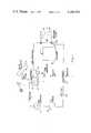
- FIG. 1is a schematic illustration of the heat pump utilizing the absorption-desorption system using ammonia as the refrigerant, and ammoniated ammonium chloride as the working fluid.
- the heat pumpis shown for operation in a continuous heating and/or cooling mode requiring separate vessels for the generator and the absorber.
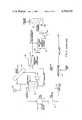
- FIG. 2is a schematic illustration of the heat pump in a heating mode adapted for use during warm days and cool nights in a typical residential unit calling for cooling of a zone to be air conditioned during the warm day, and heating of the zone in the cold night, for around-the-clock thermostatic control of the zone.
- FIG. 3is a schmatic illustration of the heat pump in a cooling mode adapted for use during warm days and warm nights in a typical residential unit calling for cooling of the zone to be air conditioned.
- FIG. 4is a graph showing the equilibrium curves for high ammoniate which is represented as NH 4 Cl.3NH 3 and ammonia; the curve for low ammoniate (absorbent) represented as NH 4 Cl.NH 3 is substantially superimposed on the curve for NH 4 Cl.3NH 3 in the temperature range shown, indicating the unique equilibrium properties of the ammoniate which permit operation of the heat pump with a low temperature heat source.
- this inventionis especially well-suited to the use of geothermal or solar heat at a temperature as low as 65° C. to provide refrigeration.
- the system of the inventionis particularly directed to cooling a dwelling unit, such as a single family house, both during the day and the night, when the system is used as an absorption refrigeration system.
- a dwelling unitsuch as a single family house
- the systemprovides heat for the house.
- a batch modethat is, cyclically to cool and heat the house alternately
- the systemis especially practical to cool the house during a warm day and then, to heat the house during a cool night, typical of the weather which is quite prevalent in the southeastern parts of the United States and many other regions of the world where geothermal and solar heat sources are available.
- the particular working fluid of this inventionis formed as a liquid ammoniate consisting essentially of a reaction product or complex of ammonia with ammonium chloride.
- complexis used hereafter to describe what is also regarded as being the reaction product of ammonia with the ammonium chloride (NH 4 Cl) salt, because the precise manner in which the ammonia is chemically combined with the salt is not known.
- NH 4 Clammonium chloride
- the complexcontain a minimum proportion of ammonia. It is desirable that this minimum proportion of ammonia in the complex be maintained substantially constant when it is drawn from the generator, prior to the absorbent absorbing additional ammonia.
- chloride absorbentIn the low ammoniate complex of ammonia and ammonium chloride (referred to hereafter as "chloride absorbent"), the minimum amount of ammonia is about one mole of ammonia per mole of ammonium chloride, so that about 53.5 parts by weight (wt) of ammonium chloride are chemically combined with about 17 parts by wt of ammonia.
- the reactionmay be represented as follows:
- At least about 24 percent (%) by wt of the chloride absorbentconsists of ammonia.
- the low ammoniateWhen the low ammoniate is enriched by absorbing additional ammonia and becomes high ammoniate it contains about 3 moles of ammonia per mole of ammonium chloride, so that about 53.5 parts of ammonium chloride are chemically combined with about 51 parts by wt of ammonia.
- the reactionmay be represented as follows:
- At least about 48.6% by wt of the high ammoniateconsists of ammonia.
- FIG. 1there is schematically illustrated, with the main components labeled, the heat pump of this invention for continuous operation, utilizing ammoniated ammonium chloride as the working fluid, irrespective of whether it is used in an absorption refrigeration mode typical of summer operation, or in a heating mode during cold weather.
- Ammoniais desorbed from the high ammoniate in a generator indicated generally by reference numeral 10.
- the generatoris in open fluid communication with an ammonia condenser indicated generally by reference numeral 11.
- Condensed ammoniaflows into an ammonia tank indicated generally by reference numeral 12, from which liquid ammonia passes through expansion valve 13 into evaporator 14 over which warm air to be cooled is flowed, and by so doing, is chilled.
- Warmed ammonia vapors from the evaporatorare ducted to the suction of an ammoniate recirculation pump 21.
- the vaporsare absorbed in the ammoniate which is flow proportioned in any predetermined ratio between an absorber indicated generally by reference numeral 15, and an ammoniate cooler 25.
- Recirculated low ammoniateis thus gradually enriched with ammonia until the low ammoniate becomes high ammoniate.
- the generatoris provided with a heating core 16 through which a heat source such as a heat transfer fluid from a solar collector 17 is pumped by pump 18 at a temperature sufficiently high to desorb ammonia from the high ammoniate held under elevated pressure in the generator.
- An expansion tank 19is preferably provided in the recirculation loop of the heat transfer fluid between solar collector 17 and generator 10 (hereafter "generator heat transfer loop").
- a preferred pressure in the generatoris in the range from about 140 psia to about 200 psia and the preferred temperature of the heat source is in the range from about 65° C. to about 90° C. It will be apparent that the upper limit of the temperature of the heat source is arbitrary and may be as high as about 200° C.
- the lower limitis determined by the temperature differential which is the driving force for desorbing the ammonia from the working fluid. Since this invention is most particularly directed to utilizing a heat source such as a geothermal stream or a fluid heat transfer stream heated in a solar collector, the invention is practical and will be most beneficial where the temperature of the heat source is about 65° C.
- the systemoperates in two well-defined modes, namely the charging or "charge” mode and the discharging or “discharge” mode.
- the charge modethe system utilizes the generator and its source of heat, and includes the ammonia condenser.
- the discharge mode of the systemutilizes the ammonia tank, expansion valve, evaporator, and absorber with its cooling loop.
- Working fluidis continuously provided to the generator by recirculation pump 21 which draws high ammoniate from the absorber 15.
- the discharge from pump 21 flow-controlled to ammoniate cooler 25may be cooled by air to be heated and recirculated, the ammoniate cooler serving as an air heater.
- the low ammoniateflows into the absorber, the flow being controlled by valve 22.
- the absorberis provided with a cooling coil (not shown) through which a heat transfer fluid such as oil is recirculated by an oil pump (not shown) to the finned heat exchange tubes 27 in the ammoniate cooler.
- a valved stubis conventionally provided in the absorber heat transfer loop, to charge it with oil.
- Any conventional heat transfer fluidmay be used, for example petroleum oil, glycols, and various commercially available heat transfer fluids such as those available under the Dowtherm brand name if the temperature of the fluid in the loop is to be relatively high.
- watermay be used, as is the case when heat transfer fluid from a solar collector, or a waste water heat source is used in the generator heat transfer loop to desorb ammonia in the generator.
- cooling of the heat transfer fluid in the absorber-heater loopwill preferably be effected by cooling water recirculated from a cooling tower.
- cooling of the watermay be provided with a cooling chamber.
- ammoniamay be condensed by heat exchange with ambient air or with cooling water from the cooling tower or chamber (also referred to as an "evaporative cooler"). It is most preferred to maintain a high enough pressure in the generator to condense the ammonia vapors driven from it with ambient air.
- heat transfer fluid from the solar collectoris at a temperature of about 71° C. as it enters the heating core.
- the flow rateis sufficient to raise the temperature of high ammoniate in the generator to about 60° C. at which the ammonia vapor pressure is about 240 psia, as can be read from FIG. 4.
- Ammoniais condensed by rejecting heat to the atmosphere and condensing in the ammonia tank where it collects at a temperature of about 38° C. and 200 psia.
- liquid ammonia from the ammonia tank 12 at 200 psiaflows through expansion valve 13 where it is vaporized in the evaporator 14 and picks up heat from the air to be cooled.
- the ammonia vaporthen flows into the absorber where it complexes or "reacts" with low ammoniate giving off heat at about 35° C. at which the pressure is about 85 psia.
- heatis rejected to the atmosphere by circulating ammoniate through an air cooled heat exchanger, namely ammoniate cooler 25.
- a prototype of a system capable of heating and/or cooling a typical single family dwellingis schematically illustrated in its heating mode in FIG. 2.
- the systemis charged by bringing heat from the solar collector 17 into the generator at 150° F.
- Ammoniais condensed in the ammonia condenser 11 by rejecting heat to ambient air at a temperature in the range from about -1.1° C. to about 15.6° C.
- the heated ambient air from out the ammonia condenser 11may be ducted to the house, or to the air heater 25 for further heating before it is recirculated to the house.
- Liquid ammoniaflows from the condenser into the ammonia tank 12 where it is held at a temperature of about 32.2° C. and a pressure of about 190 psia.
- liquid ammonia at 190 psiaflows through an expansion valve where it is vaporized and picks up heat from a low temperature source such as the ambient air at a temperature in the range from about -1.1° C. to about 15.6° C.
- the vaporflows to the absorber 15 where it is reacted with low ammoniate giving off heat.
- the absorberis used for storage of the ammoniate at about 35° C. and a pressure of about 85 psia.
- the ammoniateis circulated from the abosrber to the air heater 25 which heats air circulated to the building.
- an ammonia heat exchanger 28in which ammonia vapors from the evaporator 14 are heated by contact with finned tubes 31 through which liquid ammonia from the storage tank is flowed before it is expanded in the expansion valve 13.
- the warmed vapors from the ammonia heat exchanger 28flow to the inlet of the ammoniate recirculation pump 21 where they are absorbed, generating heat which is transferred to air recirculated through the air heater 25.
- the cooled ammoniate from the air heaterflows to the absorber or to the generator where it is reheated by the low temperature heat source.
- the systemis intended to be used with an intermittent heat source such as solar.
- an intermittent heat sourcesuch as solar.
- the ammoniateis circulated through the generator to drive off the ammonia and reduce the molar concentration of the ammonium chloride to its lower level (NH 4 Cl.NH 3 ).
- the ammoniais stored in the ammonia storage tank. At night this ammonia flows on demand to the absorber to generate heat.
- the system of this inventionis most particularly suited to provide refrigeration where low temperature heat is abundant.
- FIG. 3Operation of the system in the cooling mode is schematically illustrated in FIG. 3 wherein heat transfer fluid from a solar collector enters generator 10 and heats high ammoniate to a temperature of about 60° C. at which the pressure in the generator is about 190 psia.
- Ammonia liberatedmay be cooled by heat exchange with ambient air in a condenser as shown in FIG. 2, but is preferably cooled by heat exchange with cooling water in an evaporative cooler 11 because ambient air temperatures are likely to be too high to be economical.
- the condensed ammoniaflows into the ammonia storage tank 12, the temperature of the condensed ammonia being in the range from about 90° F. to about 100° F.
- the liquid ammoniais expanded in expansion valve 13 into evaporator 14 where the heat of vaporization is provided by air recirculated through the house which is to be cooled.
- the ammonia vaporsare fed to the inlet of pump 21 where it is absorbed in low ammoniate with generation of heat which is dissipated in water cooled chamber 25 by heat exchange with cooling water.
- the air heater used in the heating mode shown in FIG. 2may be used to cool the ammoniate by heat exchange with ambient air, with appropriate changes in ducting, if the ambient air temperature is low enough.
- Cooled low ammoniateis led into the absorber which also serves as a storage tank.
- the efficiency of the systemis improved by use of the heat exchanger 29.
- the heat contained in the low ammoniate leaving the generatoris transferred to the high ammoniate flow to the generator.
- a typical refrigeration system using ammoniated ammonium chloride as the working fluidis compared in Table I hereunder with a typical ammonia-water system when each is operated with air-cooled condensers and each provides an evaporator temperature of 4.4° C.
- the ammonia-water systemrequires a generator temperature above the boiling point of water (121° C. is used) while the generator of the claimed system operates at 60° C.
- the relevant figures for the ammonia-water systemare reproduced from Table I in U.S. Pat. No. 3,458,445 and are believed to be substantially correct, except for the ideal C.O.P. (coefficient of performance) which cannot be corroborated as the method for computing it is not stated in the patent.
- the C.O.P.has been computed for the claimed system as follows:
- the energy input(ammonia flow) (heat of reaction)
- the figures for the claimed systemhave been calculated based upon the performance of a typical system designed for a residential unit capable of storing 500,000 BTU for heating and 250,000 BTU for cooling.
- the heating and cooling ratescan be up to 70,000 BTU/hr and do not materially affect the comparison of relevant figures for the two systems.
- the pumping factor RP used in the Tableis defined as the pounds of the solution circulated between the generator and absorber per unit time divided by the pounds of ammonia vaporized per unit time.
- the pumping factoris thus a measure of the quantity of solution needed for circulation between the absorber and the generator to vaporize one pound of ammonia. The lower the pumping factor the more efficient is the system, all other things being the same.
- this systemoperates with a coefficient of performance which is generally as high as 90% of theoretical, and often in the range from about 90% to 95% of theoretical, irrespective of how the theoretical C.O.P. is to be calculated.
Landscapes
- Engineering & Computer Science (AREA)
- Physics & Mathematics (AREA)
- Mechanical Engineering (AREA)
- Thermal Sciences (AREA)
- General Engineering & Computer Science (AREA)
- Chemical & Material Sciences (AREA)
- Chemical Kinetics & Catalysis (AREA)
- General Chemical & Material Sciences (AREA)
- Sorption Type Refrigeration Machines (AREA)
Abstract
Description
NH.sub.4 Cl+NH.sub.3 ⃡NH.sub.4 Cl.NH.sub.3
NH.sub.4 Cl+3NH.sub.3 ⃡NH.sub.4 Cl.3NH.sub.3
TABLE I ______________________________________ Comparison of NH.sub.3 --H.sub.2 O and NH.sub.3.(1-3)NH.sub.4 Cl working fluids Design Variables NH.sub.3 --H.sub.2 O NH.sub.3.NH.sub.4 Cl ______________________________________ Evaporator temp., °F. 40 40 Condenser temp., °F. 120 120 Generator temp., °F. 250 250 Absorber conc., wt % NH.sub.3 44.3 48.8 Generator conc., wt % NH.sub.3 35.0 24. Pumping factor, RP 6.0 1.86 Heat of vap., BTU/# 536 536 Heat of reaction, BTU/# 751 700 Pump work, HP/ton 5.8 × 10.sup.-2 0.6 × 10.sup.-2 Heat exchange load, BTU/ton min. 391 286 Ideal C.O.P 0.714 0.766 ______________________________________
Claims (9)
Priority Applications (1)
| Application Number | Priority Date | Filing Date | Title |
|---|---|---|---|
| US06/287,992US4386501A (en) | 1981-07-29 | 1981-07-29 | Heat pump using liquid ammoniated ammonium chloride, and thermal storage system |
Applications Claiming Priority (1)
| Application Number | Priority Date | Filing Date | Title |
|---|---|---|---|
| US06/287,992US4386501A (en) | 1981-07-29 | 1981-07-29 | Heat pump using liquid ammoniated ammonium chloride, and thermal storage system |
Publications (1)
| Publication Number | Publication Date |
|---|---|
| US4386501Atrue US4386501A (en) | 1983-06-07 |
Family
ID=23105284
Family Applications (1)
| Application Number | Title | Priority Date | Filing Date |
|---|---|---|---|
| US06/287,992Expired - Fee RelatedUS4386501A (en) | 1981-07-29 | 1981-07-29 | Heat pump using liquid ammoniated ammonium chloride, and thermal storage system |
Country Status (1)
| Country | Link |
|---|---|
| US (1) | US4386501A (en) |
Cited By (28)
| Publication number | Priority date | Publication date | Assignee | Title |
|---|---|---|---|---|
| FR2548340A1 (en)* | 1983-07-01 | 1985-01-04 | Elf Aquitaine | THREE PHASE HEAT PUMP |
| WO1986001880A1 (en)* | 1984-09-13 | 1986-03-27 | Gadd, Olof | A chemo-thermal plant |
| US5666818A (en)* | 1995-12-26 | 1997-09-16 | Instituto Tecnologico And De Estudios Superiores | Solar driven ammonia-absorption cooling machine |
| US5685152A (en)* | 1995-04-19 | 1997-11-11 | Sterling; Jeffrey S. | Apparatus and method for converting thermal energy to mechanical energy |
| US20050103615A1 (en)* | 2003-10-14 | 2005-05-19 | Ritchey Jonathan G. | Atmospheric water collection device |
| US20080283622A1 (en)* | 2007-05-16 | 2008-11-20 | Dieter Weiss | Method for the transport of heat energy and apparatus for the carrying out of such a method |
| US20100140286A1 (en)* | 2008-12-08 | 2010-06-10 | Michael Christopher Quinn | Portable beverage machine |
| CN101818967A (en)* | 2010-05-20 | 2010-09-01 | 上海交通大学 | Composite energy storage and supply device via thermochemical temperature swing adsorption combined cold-heat supply |
| US20100252788A1 (en)* | 2009-04-02 | 2010-10-07 | Valterra Products, Inc. | Vehicle leveling device |
| US20100266475A1 (en)* | 2009-04-16 | 2010-10-21 | Amminex A/S | Production of Saturated Ammonia Storage Materials |
| US20110108020A1 (en)* | 2009-11-11 | 2011-05-12 | Mcenerney Bryan William | Ballast member for reducing active volume of a vessel |
| US20110314844A1 (en)* | 2010-06-25 | 2011-12-29 | Junjie Gu | Method and apparatus for waste heat recovery and absorption gases used as working fluid therein |
| JP2012117783A (en)* | 2010-12-02 | 2012-06-21 | Kawasaki Thermal Engineering Co Ltd | Hot water utilization system |
| CN102997358A (en)* | 2012-12-03 | 2013-03-27 | 中国科学院广州能源研究所 | Non-water taking type geothermal heat pipe air-conditioning system |
| US20130081413A1 (en)* | 2010-06-17 | 2013-04-04 | Tomas Åbyhammar | Method in treating solvent containing gas |
| CN103528258A (en)* | 2013-10-30 | 2014-01-22 | 宁波工程学院 | Mixed working medium variable concentration volume adjusting absorption heat pump system |
| WO2016169867A1 (en)* | 2015-04-22 | 2016-10-27 | Commissariat A L'energie Atomique Et Aux Energies Alternatives | Concentrating solar power (csp) plant with chemical storage |
| US20170120725A1 (en)* | 2015-11-04 | 2017-05-04 | Toyota Motor Engineering & Manufacturing North America, Inc. | Absorption-based system for automotive waste heat recovery |
| US20170138649A1 (en)* | 2015-11-17 | 2017-05-18 | King Fahd University Of Petroleum And Minerals | Integrated solar absorption heat pump system |
| RU2625073C1 (en)* | 2016-07-25 | 2017-07-11 | федеральное государственное бюджетное образовательное учреждение высшего образования "Национальный исследовательский университет "МЭИ" (ФГБОУ ВО "НИУ "МЭИ") | Absorption refrigerator with built-in heat pump plant |
| WO2017167901A1 (en)* | 2016-03-31 | 2017-10-05 | Siemens Aktiengesellschaft | Device and method for transferring heat |
| US20170321101A1 (en)* | 2013-05-28 | 2017-11-09 | Yanjie Jeff | Refrigeration System With Dual Refrigerants and Liquid Working Fluids |
| CN107388620A (en)* | 2017-09-20 | 2017-11-24 | 河海大学常州校区 | A kind of complex type solar lithium bromide absorption type air conditioner system |
| US20170356695A1 (en)* | 2014-10-21 | 2017-12-14 | University Of Utah Research Foundation | Climate control system and associated methods |
| US20180100676A1 (en)* | 2015-03-23 | 2018-04-12 | Centre National De La Recherche Scientifique | Solar device for autonomous refrigeration by solid-gas sorption |
| US10330331B2 (en)* | 2015-11-24 | 2019-06-25 | Southeast University | Independent temperature and humidity processing air conditioning system driven by low-level thermal energy |
| US10961874B2 (en) | 2016-03-06 | 2021-03-30 | Husham Al-Ghizzy | Enhanced thermoutilizer |
| US11709023B2 (en)* | 2017-03-30 | 2023-07-25 | Nederlandse Organisatie Voor Toegepast-Natuurwetenschappelijk Onderzoek Tno | Enhanced TCM production and use |
Citations (5)
| Publication number | Priority date | Publication date | Assignee | Title |
|---|---|---|---|---|
| US1961890A (en)* | 1931-08-14 | 1934-06-05 | Chester F Hockley | Refrigeration process |
| US2184993A (en)* | 1937-03-06 | 1939-12-26 | Hoover Co | Refrigeration |
| US2185040A (en)* | 1936-11-30 | 1939-12-26 | Gen Motors Corp | Method of refrigeration and absorbent therefor |
| US2986525A (en)* | 1958-04-16 | 1961-05-30 | Hugh S Hughes | Refrigerant absorbent composition and method of producing same |
| US3520812A (en)* | 1968-02-16 | 1970-07-21 | Ray A Ecklund | Refrigerant composition containing ammonia,ethanol,and mineral oil |
- 1981
- 1981-07-29USUS06/287,992patent/US4386501A/ennot_activeExpired - Fee Related
Patent Citations (5)
| Publication number | Priority date | Publication date | Assignee | Title |
|---|---|---|---|---|
| US1961890A (en)* | 1931-08-14 | 1934-06-05 | Chester F Hockley | Refrigeration process |
| US2185040A (en)* | 1936-11-30 | 1939-12-26 | Gen Motors Corp | Method of refrigeration and absorbent therefor |
| US2184993A (en)* | 1937-03-06 | 1939-12-26 | Hoover Co | Refrigeration |
| US2986525A (en)* | 1958-04-16 | 1961-05-30 | Hugh S Hughes | Refrigerant absorbent composition and method of producing same |
| US3520812A (en)* | 1968-02-16 | 1970-07-21 | Ray A Ecklund | Refrigerant composition containing ammonia,ethanol,and mineral oil |
Cited By (41)
| Publication number | Priority date | Publication date | Assignee | Title |
|---|---|---|---|---|
| EP0130908A1 (en)* | 1983-07-01 | 1985-01-09 | Societe Nationale Elf Aquitaine | Heat transfer process with a three-phase monovariant reaction |
| FR2548340A1 (en)* | 1983-07-01 | 1985-01-04 | Elf Aquitaine | THREE PHASE HEAT PUMP |
| WO1986001880A1 (en)* | 1984-09-13 | 1986-03-27 | Gadd, Olof | A chemo-thermal plant |
| US5685152A (en)* | 1995-04-19 | 1997-11-11 | Sterling; Jeffrey S. | Apparatus and method for converting thermal energy to mechanical energy |
| US5666818A (en)* | 1995-12-26 | 1997-09-16 | Instituto Tecnologico And De Estudios Superiores | Solar driven ammonia-absorption cooling machine |
| US8196422B2 (en)* | 2003-10-14 | 2012-06-12 | Ritchey Jonathan G | Atmospheric water collection device |
| US20050103615A1 (en)* | 2003-10-14 | 2005-05-19 | Ritchey Jonathan G. | Atmospheric water collection device |
| US20100263396A1 (en)* | 2003-10-14 | 2010-10-21 | Jonathan G. Ritchey | Atmospheric water collection device |
| US20080283622A1 (en)* | 2007-05-16 | 2008-11-20 | Dieter Weiss | Method for the transport of heat energy and apparatus for the carrying out of such a method |
| US20100140286A1 (en)* | 2008-12-08 | 2010-06-10 | Michael Christopher Quinn | Portable beverage machine |
| US20100252788A1 (en)* | 2009-04-02 | 2010-10-07 | Valterra Products, Inc. | Vehicle leveling device |
| US7980532B2 (en) | 2009-04-02 | 2011-07-19 | Valterra Products, Inc. | Vehicle leveling device |
| US20100266475A1 (en)* | 2009-04-16 | 2010-10-21 | Amminex A/S | Production of Saturated Ammonia Storage Materials |
| US8084008B2 (en)* | 2009-04-16 | 2011-12-27 | Amminex A/S | Production of saturated ammonia storage materials |
| US20110108020A1 (en)* | 2009-11-11 | 2011-05-12 | Mcenerney Bryan William | Ballast member for reducing active volume of a vessel |
| CN101818967B (en)* | 2010-05-20 | 2012-08-29 | 上海交通大学 | Composite energy storage and supply device via thermochemical temperature swing adsorption combined cold-heat supply |
| CN101818967A (en)* | 2010-05-20 | 2010-09-01 | 上海交通大学 | Composite energy storage and supply device via thermochemical temperature swing adsorption combined cold-heat supply |
| US20130081413A1 (en)* | 2010-06-17 | 2013-04-04 | Tomas Åbyhammar | Method in treating solvent containing gas |
| US20110314844A1 (en)* | 2010-06-25 | 2011-12-29 | Junjie Gu | Method and apparatus for waste heat recovery and absorption gases used as working fluid therein |
| US8544284B2 (en)* | 2010-06-25 | 2013-10-01 | Petrochina North China Petrochemical Company | Method and apparatus for waste heat recovery and absorption gases used as working fluid therein |
| JP2012117783A (en)* | 2010-12-02 | 2012-06-21 | Kawasaki Thermal Engineering Co Ltd | Hot water utilization system |
| CN102997358A (en)* | 2012-12-03 | 2013-03-27 | 中国科学院广州能源研究所 | Non-water taking type geothermal heat pipe air-conditioning system |
| US20170321101A1 (en)* | 2013-05-28 | 2017-11-09 | Yanjie Jeff | Refrigeration System With Dual Refrigerants and Liquid Working Fluids |
| CN103528258A (en)* | 2013-10-30 | 2014-01-22 | 宁波工程学院 | Mixed working medium variable concentration volume adjusting absorption heat pump system |
| US20170356695A1 (en)* | 2014-10-21 | 2017-12-14 | University Of Utah Research Foundation | Climate control system and associated methods |
| US20180100676A1 (en)* | 2015-03-23 | 2018-04-12 | Centre National De La Recherche Scientifique | Solar device for autonomous refrigeration by solid-gas sorption |
| WO2016169867A1 (en)* | 2015-04-22 | 2016-10-27 | Commissariat A L'energie Atomique Et Aux Energies Alternatives | Concentrating solar power (csp) plant with chemical storage |
| FR3035486A1 (en)* | 2015-04-22 | 2016-10-28 | Commissariat Energie Atomique | SOLAR STATION WITH CONCENTRATION (CSP) WITH CHEMICAL STORAGE |
| US20170120725A1 (en)* | 2015-11-04 | 2017-05-04 | Toyota Motor Engineering & Manufacturing North America, Inc. | Absorption-based system for automotive waste heat recovery |
| US10996000B2 (en)* | 2015-11-04 | 2021-05-04 | Toyota Motor Engineering & Manufacturing North America, Inc. | Absorption-based system for automotive waste heat recovery |
| US10066856B2 (en)* | 2015-11-17 | 2018-09-04 | King Fahd University Of Petroleum And Minerals | Integrated solar absorption heat pump system |
| US10845102B2 (en)* | 2015-11-17 | 2020-11-24 | King Fahd University Of Petroleum And Minerals | Heat pump system with chilled water tank and photovoltaic thermal collector |
| US10845101B2 (en)* | 2015-11-17 | 2020-11-24 | King Fahd University Of Petroleum And Minerals | Integrated solar absorption heat pump system with evacuated tube solar collector |
| US20170138649A1 (en)* | 2015-11-17 | 2017-05-18 | King Fahd University Of Petroleum And Minerals | Integrated solar absorption heat pump system |
| US10330331B2 (en)* | 2015-11-24 | 2019-06-25 | Southeast University | Independent temperature and humidity processing air conditioning system driven by low-level thermal energy |
| US10961874B2 (en) | 2016-03-06 | 2021-03-30 | Husham Al-Ghizzy | Enhanced thermoutilizer |
| US11828201B2 (en) | 2016-03-06 | 2023-11-28 | Husham Al-Ghizzy | Enhanced thermoutilizer |
| WO2017167901A1 (en)* | 2016-03-31 | 2017-10-05 | Siemens Aktiengesellschaft | Device and method for transferring heat |
| RU2625073C1 (en)* | 2016-07-25 | 2017-07-11 | федеральное государственное бюджетное образовательное учреждение высшего образования "Национальный исследовательский университет "МЭИ" (ФГБОУ ВО "НИУ "МЭИ") | Absorption refrigerator with built-in heat pump plant |
| US11709023B2 (en)* | 2017-03-30 | 2023-07-25 | Nederlandse Organisatie Voor Toegepast-Natuurwetenschappelijk Onderzoek Tno | Enhanced TCM production and use |
| CN107388620A (en)* | 2017-09-20 | 2017-11-24 | 河海大学常州校区 | A kind of complex type solar lithium bromide absorption type air conditioner system |
Similar Documents
| Publication | Publication Date | Title |
|---|---|---|
| US4386501A (en) | Heat pump using liquid ammoniated ammonium chloride, and thermal storage system | |
| Raldow et al. | Chemical heat pumps—a basic thermodynamic analysis | |
| US5360057A (en) | Dual-temperature heat pump apparatus and system | |
| US12078385B2 (en) | Heat dissipation systems with hygroscopic working fluid | |
| US4827728A (en) | Seven-effect absorption refrigeration | |
| EP0034164B1 (en) | A method and apparatus for storing heat | |
| JPS61119954A (en) | Absorption heat pump/refrigeration system | |
| JPH09512332A (en) | Absorption cooling device and method | |
| Norton | Solar refrigeration | |
| CN103591746A (en) | Salt dissolving type temperature regulating device and method for applying same | |
| Iyoki et al. | Performance characteristics of the water-lithium bromide-zinc chloride-calcium bromide absorption refrigerating machine, absorption heat pump and absorption heat transformer | |
| Bjurström et al. | The absorption process for heating, cooling and energy storage—an historical survey | |
| He et al. | Performance prediction of refrigerant-DMF solutions in a single-stage solar-powered absorption refrigeration system at low generating temperatures | |
| Duffy et al. | Investigation of a novel combined ab-and ad-sorption based thermal energy storage and upgrade system | |
| US4487027A (en) | Hyperabsorption space conditioning process and apparatus | |
| Auh | Survey of absorption cooling technology in solar applications | |
| Stanish et al. | Salt hydrates as absorbents in heat pump cycles | |
| Sheridan et al. | A novel latent heat storage for solar space heating systems: refrigerant storage | |
| US4509336A (en) | Air conditioning apparatus | |
| Siddiqui et al. | Economic evaluation of biogas for optimizing generator temperature in a vapour-absorption system | |
| US4524759A (en) | Process for the reversible transfer of thermal energy and heat transfer system useful therein | |
| US4784783A (en) | Non-volatile high-lift ammonia vapor absorbent | |
| Titlov et al. | Optimizing NH3-H2O absorption system to produce water from ambient air | |
| Ahachad et al. | Solar absorption heat transformer applications to absorption refrigerating machines | |
| Arunkumar et al. | Design and fabrication of solar powered lithium bromide vapour absorption refrigeration system |
Legal Events
| Date | Code | Title | Description |
|---|---|---|---|
| AS | Assignment | Owner name:MARTIN MARIETTA CORPORATION, 6801 ROCKLEDGE DR.BET Free format text:ASSIGNMENT OF ASSIGNORS INTEREST.;ASSIGNOR:JAEGER, FREDERICK A.;REEL/FRAME:003913/0360 Effective date:19810716 Owner name:MARTIN MARIETTA CORPORATION, MARYLAND Free format text:ASSIGNMENT OF ASSIGNORS INTEREST;ASSIGNOR:JAEGER, FREDERICK A.;REEL/FRAME:003913/0360 Effective date:19810716 | |
| FEPP | Fee payment procedure | Free format text:PAYOR NUMBER ASSIGNED (ORIGINAL EVENT CODE: ASPN); ENTITY STATUS OF PATENT OWNER: LARGE ENTITY | |
| MAFP | Maintenance fee payment | Free format text:PAYMENT OF MAINTENANCE FEE, 4TH YEAR, PL 96-517 (ORIGINAL EVENT CODE: M170); ENTITY STATUS OF PATENT OWNER: LARGE ENTITY Year of fee payment:4 | |
| MAFP | Maintenance fee payment | Free format text:PAYMENT OF MAINTENANCE FEE, 8TH YEAR, PL 96-517 (ORIGINAL EVENT CODE: M171); ENTITY STATUS OF PATENT OWNER: LARGE ENTITY Year of fee payment:8 | |
| FEPP | Fee payment procedure | Free format text:PAYOR NUMBER ASSIGNED (ORIGINAL EVENT CODE: ASPN); ENTITY STATUS OF PATENT OWNER: LARGE ENTITY Free format text:PAYER NUMBER DE-ASSIGNED (ORIGINAL EVENT CODE: RMPN); ENTITY STATUS OF PATENT OWNER: LARGE ENTITY | |
| FEPP | Fee payment procedure | Free format text:MAINTENANCE FEE REMINDER MAILED (ORIGINAL EVENT CODE: REM.); ENTITY STATUS OF PATENT OWNER: LARGE ENTITY | |
| LAPS | Lapse for failure to pay maintenance fees | ||
| FP | Lapsed due to failure to pay maintenance fee | Effective date:19950607 | |
| STCH | Information on status: patent discontinuation | Free format text:PATENT EXPIRED DUE TO NONPAYMENT OF MAINTENANCE FEES UNDER 37 CFR 1.362 |