US4383805A - Gas compressor of the scroll type having delayed suction closing capacity modulation - Google Patents
Gas compressor of the scroll type having delayed suction closing capacity modulationDownload PDFInfo
- Publication number
- US4383805A US4383805AUS06/202,967US20296780AUS4383805AUS 4383805 AUS4383805 AUS 4383805AUS 20296780 AUS20296780 AUS 20296780AUS 4383805 AUS4383805 AUS 4383805A
- Authority
- US
- United States
- Prior art keywords
- end plate
- passage
- communication
- wrap element
- compressor
- Prior art date
- Legal status (The legal status is an assumption and is not a legal conclusion. Google has not performed a legal analysis and makes no representation as to the accuracy of the status listed.)
- Expired - Lifetime
Links
- 230000003111delayed effectEffects0.000title1
- 238000004891communicationMethods0.000claimsabstractdescription43
- 230000000903blocking effectEffects0.000claimsabstractdescription8
- 238000007789sealingMethods0.000claimsdescription9
- 238000006073displacement reactionMethods0.000claimsdescription4
- 238000007599dischargingMethods0.000claimsdescription2
- 230000002250progressing effectEffects0.000claimsdescription2
- 238000011144upstream manufacturingMethods0.000claims1
- 230000006835compressionEffects0.000abstractdescription13
- 238000007906compressionMethods0.000abstractdescription13
- 239000012530fluidSubstances0.000description11
- 230000008901benefitEffects0.000description4
- 238000005057refrigerationMethods0.000description4
- 238000004378air conditioningMethods0.000description3
- 238000001816coolingMethods0.000description3
- 230000000694effectsEffects0.000description3
- 239000007788liquidSubstances0.000description3
- 238000005461lubricationMethods0.000description3
- 230000008878couplingEffects0.000description2
- 238000010168coupling processMethods0.000description2
- 238000005859coupling reactionMethods0.000description2
- 238000013519translationMethods0.000description2
- 238000013459approachMethods0.000description1
- 230000015572biosynthetic processEffects0.000description1
- 238000005266castingMethods0.000description1
- 230000003028elevating effectEffects0.000description1
- 238000010438heat treatmentMethods0.000description1
- 238000004519manufacturing processMethods0.000description1
- 239000000463materialSubstances0.000description1
- 230000007246mechanismEffects0.000description1
- 238000000034methodMethods0.000description1
- 238000012986modificationMethods0.000description1
- 230000004048modificationEffects0.000description1
- 230000009467reductionEffects0.000description1
- 239000003507refrigerantSubstances0.000description1
- 239000011800void materialSubstances0.000description1
Images

Classifications
- F—MECHANICAL ENGINEERING; LIGHTING; HEATING; WEAPONS; BLASTING
- F04—POSITIVE - DISPLACEMENT MACHINES FOR LIQUIDS; PUMPS FOR LIQUIDS OR ELASTIC FLUIDS
- F04C—ROTARY-PISTON, OR OSCILLATING-PISTON, POSITIVE-DISPLACEMENT MACHINES FOR LIQUIDS; ROTARY-PISTON, OR OSCILLATING-PISTON, POSITIVE-DISPLACEMENT PUMPS
- F04C28/00—Control of, monitoring of, or safety arrangements for, pumps or pumping installations specially adapted for elastic fluids
- F04C28/10—Control of, monitoring of, or safety arrangements for, pumps or pumping installations specially adapted for elastic fluids characterised by changing the positions of the inlet or outlet openings with respect to the working chamber
- F04C28/16—Control of, monitoring of, or safety arrangements for, pumps or pumping installations specially adapted for elastic fluids characterised by changing the positions of the inlet or outlet openings with respect to the working chamber using lift valves
Definitions
- the present inventionrelates generally to the field of gas compressors of the scroll type, and is particularly directed to such a compressor capable of operation at variable capacities so as to have utility in the field of refrigeration and air conditioning, or other applications wherein a compressor of variable capacity is indicated.
- scroll-type fluid apparatusIn the field of positive displacement fluid apparatus, there exists a class or category generally referred to as scroll-type fluid apparatus which are characterized by the provision of wrap elements defining flank surfaces of generally spiroidal configuration about respective axes, which wrap elements lie in intermeshing, angularly offset relationship with their axes generally parallel such that relative orbital motion between the wrap elements results in the formation of one or more moving volumes between the wrap elements, defined by moving lines of coaction between the wrap elements at which their flank surfaces lie substantially tangent to each other.
- the precise shape of the generally spiroidal flank surfacescomprise an involute of a circle, however, the term "generally spiroidal" is intended to encompass any form providing the requisite moving volumes during relative orbital motion between the wrap elements.
- end plate meansare provided in sealing relationship to the wrap elements as they undergo relative orbital motion such that the moving volumes are effectively sealed.
- scroll-type fluid apparatushave utility in a wide variety of applications, including gas compressors or vacuum pumps for elevating the pressure of a gaseous working fluid; liquid pumps for transporting a liquid working fluid; or as an expansion engine for producing mechanical work by the expansion of a relatively high pressure gaseous working fluid.
- gas compressors or vacuum pumpsfor elevating the pressure of a gaseous working fluid
- liquid pumpsfor transporting a liquid working fluid
- expansion enginefor producing mechanical work by the expansion of a relatively high pressure gaseous working fluid.
- the moving volumes defined between wrap elementsoriginate at a radially outer portion thereof and progress inwardly while their volume is reduced, resulting in compression of the working gas which is then discharged at a radially inner portion of the wrap elements.
- Liquid pumpsfunction in a similar fashion with the wrap elements configured such that no appreciable reduction in volume occurs as the volumes progress radially inwardly, while scroll-type expansion engines receive a relatively high pressure gaseous working fluid at the radially inner portion of their wrap elements, which then progresses radially outwardly in the moving volumes as they increase in volume, resulting in expansion of the working fluid and production of mechanical work.
- a second consideration relevant to the relative orbital motion between wrap elementsis the manner in which their flank surfaces are permitted to coact with each other; i.e., is actual contact permitted therebetween along the lines at which the surfaces lie substantially tangent, accompanied by a radial sealing force therebetween; or are constraints imposed thereon so as to maintain a slight clearance or gap therebetween.
- the formermay be referred to as "radially compliant” type, while the latter may be referred to as "fixed-crank” type.
- the term “moving line coaction”is intended to be descriptive of both types, while the term “actual moving line contact” is limited to the radially compliant type.
- U.S. Pat. No. 3,924,977for disclosure of a radially compliant type drive mechanism
- U.S. Pat. No. 4,082,484is illustrative of the fixed-crank type.
- the compressorbe provided with variable capacity operation; particularly, in the field of refrigeration and air conditioning wherein gas compressors are utilized to compress a refrigerant gas such as Freon (a trademark of Du Pont), it is desirable that a particular refrigeration system be of variable capacity as to match the cooling or heating output of the system to the demand therefore at any particular time.
- a refrigerant gassuch as Freon (a trademark of Du Pont)
- many such systems todayutilize centrifugal or reciprocating gas compressors provided with means for varying their capacity. It would, however, due to certain advantages associated with gas compressors of the scroll type, be desirable that this type compressor be provided with means for selectively varying its capacity so as to enable its application in the field of refrigeration and air conditioning, or in other applications where such variable capacity operation is required.
- a gas compressor of the scroll typeincludes first and second wrap elements defining respective flank surfaces of generally spiroidaL configuration about their axes, the wrap elements being disposed in intermeshing, angularly offset relationship with their axes generally parallel, and with end plate means in overlying, substantially sealing relationship to first and second axial tip portions of the wrap elements.
- Drive meansare provided for effecting relative orbital motion between the wrap elements such that moving line coaction between the flank surfaces thereof defines between the end plate means one or more moving volumes originating at a radially outer portion of the wrap elements and progressing radially inwardly to an inner portion thereof, which moving volumes are bounded initially by a single, leading moving line of coaction, then by both leading and trailing lines of coaction so as to define a closed moving volume, thence by a single trailing line of coaction so as to define a discharge volume.
- Port meansare provided for admitting a working gas at suction pressure to the suction volumes about the periphery of the wrap elements and for discharging compressed gas from a radially inner portion of the wrap elements.
- passage meansare provided extending through the end plate means from a location in communication with the closed moving volumes from at least the time they are formed by their trailing moving line of coaction until they have progressed radially inwardly to a predetermined position, to a location in communication with working gas normally at suction pressure during operation of the compressor.
- Valve meansare further provided for selectively blocking flow through the passage means, whereby the gas compressor operates at a relatively high capacity; and for permitting flow through the passage means, whereby gas is exhausted via the passage means from said closed moving volume as it is reduced in volume and until it has progressed radially inwardly to the aforesaid predetermined position, whereby the capacity of the compressor is reduced.
- the end plate meanscomprise a first end plate sealingly affixed to a first axial tip portion of the first wrap element and a second end plate sealingly affixed to a first axial tip portion of the second wrap element; and wherein means are provided for maintaining the second wrap element and end plate in a fixed position while the drive means are operative to drive the first wrap element and end plate in an orbital path with respect thereto.
- the passage meansconveniently extend through the second, fixed end plate.
- the compressoris disposed within a hermetic shell to which working gas is admitted such that the interior thereof is maintained at suction pressure, such that the passage means extend through the second end plate to a location in communication with the interior of the shell. In this manner, working gas which is exhausted from the closed moving volumes via the passage means is simply returned to the interior of the hermetic shell without the need for additional fluid flow passages.
- the valve means associated with the unloader meanspreferably include a valve element movable between a first position blocking flow through the passage means and a second position permitting flow therethrough, said valve element having a generally planar surface which lies substantially flush to a generally planar surface of the end plate means. In this manner, no undesirable clearance volume is introduced into the compressor which would impair its operating efficiency at full capacity, and leakage across the axial tip portion of the wrap element is minimized or avoided.
- the passage means referred topreferably comprise first and second passages extending through the end plate means, the first passage being at a location so as to be in communication with first and second closed moving volumes at least from the time they are formed by their associated trailing lines of coaction, and a second passage extending through the end plate means at a second location so as to be in communication with the first and second closed moving volumes at least from the time they are no longer in communication with the first passage as they progress radially inwardly toward the predetermined positions at which compression is permitted to begin.
- three discrete capacitiesmay be obtained: full capacity with both passages closed; a first reduced capacity with the radially outer passage open; and a second further reduced capacity with both passages open.
- valve meansare actuated to their position blocking flow through the passage means by working gas at discharge pressure such that, at startup of the compressor from a standing start, the valve means are in their open position permitting flow through the passage means until the discharge pressure of the compressor reaches a predetermined value.
- a primary object of the present inventionto provide a gas compressor of the scroll type which includes unloader means for selectively varying its capacity by delaying the point at which compression of the working gas begins as the closed moving volumes defined between wrap elements of the compressor progress radially inwardly.
- Yet another object of the inventionis to provide a valve arrangement for the passage means which does not interfere with normal operation of the compressor and, in particular, does not effect its operating efficiency.
- a fourth object of the inventionis to provide a gas compressor having at least three discrete operating capacities, through the provision of two passages so-located as to bring about the desired variations in capacity.
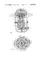
- FIG. 1is a vertical cross section view taken along the line 1--1 of FIG. 2.
- FIG. 2is a cross section view taken along line 2--2 of FIG. 1.
- FIG. 3is a cross section view taken along line 3--3 of FIG. 1.
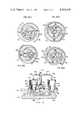
- FIG. 4is a series of cross section views taken along line 4--4 of FIG. 1, illustrating the wrap elements at sequential operating positions taken at 90° intervals.
- FIG. 5is a series of cross section views similar to those of FIG. 4 illustrating a second embodiment of the invention.
- FIG. 6is a cross section view taken along line 6--6 of FIG. 4 illustrating in detail the valve means of the present invention.
- fluid apparatus of the positive displacement scroll typeare illustrated in the form of a gas compressor indicated generally by reference numeral 1, and disposed within a hermetic casing or shell 2.
- a crankcase housing 3includes a plurality of supporting legs 4 which are suitably affixed to the inner periphery of shell 2 so as to support the compressor therein.
- Crankshaft meansare rotatably supported within housing 3 and include a shaft 5 rotatable on a shaft axis and crank means 6 in the form of a crank pin or stub shaft affixed thereto and radially offset therefrom along a crank axis.
- shaft 5is supported by an upper roller bearing assembly 7 and a lower ball bearing assembly 8, which bearings also serve to support any axial loads imposed upon shaft 5 due to the shoulders machined on shaft 5 and housing 3, as shown.
- An electric drive motorincludes a rotor 9 affixed to the lower end of shaft 5 and a stator 10 fastened to housing 3 by a plurality of bolts 11. Surrounding the lower end of stator 10 is a shroud 12 for receiving gas to be compressed from inlet conduit 13 and directing same over the drive motor for cooling purposes.
- the lowermost end of shaft 5includes a centrifugal oil pump, indicated generally by reference numeral 14, which pumps oil from a sump in the lower portion of shell 2, via one or more axial passages in shaft 5, to the various components of the compressor requiring lubrication. Since the particulars of the lubrication system do not form a part of the present invention, nor is an understanding thereof critical to the invention, no detailed explanation thereof is believed warranted. Reference may be had to U.S. Pat. No. 4,064,279 for an example of this type lubrication system.
- Scroll member 15Affixed to the upper portion of housing 3 is a fixed, or second, scroll member indicated generally at 15 and comprising a second wrap element 15a which, as best seen in FIG. 3, defines respective inner and outer flank surfaces 15b and 15c of generally spiroidal configuration about a second axis and extending between a first axial tip portion 15d and a second axial tip portion 15e.
- Scroll member 15further includes end plate means in overlying, substantially sealing relationship to axial tip portion 15d and, in the embodiment illustrated, comprise an end plate 15f sealingly affixed to axial tip portion 15d.
- Scroll member 15, including wrap element 15a and end plate 15fmay be machined from a single casting or block of material; or, in the alternative, wrap element 15a may be formed separately and then suitably attached to end plate 15f.
- end plate 15fis attached to housing 3 by four column members 16 spaced about its periphery.
- An orbiting, or first scroll member indicated generally at 17includes a first wrap element 17a which, as best seen in FIG. 3, defines respective inner and outer flank surfaces 17b and 17c of generally spiroidal configuration about a first axis and extending between a first axial tip portion 17d and a second axial tip portion 17e.
- Scroll member 17also includes end plate means in overlying, substantially sealing relationship to axial tip portion 17d and, in the embodiment illustrated, comprise a first end plate 17f sealingly affixed to axial tip portion 17d.
- Scroll member 17may be fabricated using those techniques, outlined with respect to scroll member 15.
- first and second wrap elements 17a and 15aare disposed in intermeshing, angularly offset relationship with their axes generally parallel, and such that second axial tip portions 17e and 15e extend to positions in substantial sealing relationship with end plates 15f and 17f, respectively.
- axial tip portions 17e and 15emay advantageously be provided with tip seals in order to improve compressor performance by reducing leakage.
- a variety of such tip sealsare disclosed in U.S. Pat. No. 3,994,636.
- wrap elements 15a and 17adefine a first series of moving volumes 18a, 18b between flank surfaces 15b and 17c; and a second series of moving volumes 19a, 19b between flank surfaces 17b and 15c; which volumes progress radially inwardly as wrap element 17a orbits with respect to wrap element 15a in a counterclockwise direction as viewed in FIG. 3.
- Volumes 18a, 19acomprise suction volumes bounded by a single, leading line of coaction, while volumes 18b, 19b are bounded by both leading and trailing lines of coaction and are reduced in volume as wrap element 17a undergoes orbital motion until the volumes are bounded by only a trailing line of coaction and the compressed gas is discharged via port 20 and discharge conduit 21.
- compressor 1receives gas to be compressed from conduit 13 after it has passed over the drive motor as previously described, which gas enters volumes 18a, 19a from about the periphery of wrap elements 15, 17, and is discharged therefrom via port 20 and conduit 21.
- radially compliant drive meansare provided such that actual moving line contact is permitted between the flank surfaces of wrap elements 15a and 17a, and a sealing force acts therebetween.
- linkage meansinclude linkage means operatively interconnecting shaft 5 and wrap element 17a via its attached end plate 17f, which linkage means comprise a linkage member 22 having a first bore 22a rotatably engaging stub shaft 6 of crankshaft 5; and a second bore 22b rotatably engaging a stub shaft 17g depending from end plate 17f along a third axis.
- Suitable bearing meanssuch as journal bearing 23 between bore 22a and stub shaft 5; and roller bearing 24 between bore 22b and stub shaft 17g are provided as shown.
- stub shaft 17g of scroll member 17is free to undergo at least limited motion in a radial direction with respect to the axis of shaft 5 as linkage member 22 pivots or swings about the axis of stub shaft 6, thereby permitting actual line contact between the flank surfaces of wrap elements 17a and 15a. It can further be seen that, upon rotation of shaft 5, scroll member 17 will undergo orbital motion with respect to fixed scroll member 15.
- Linkage member 22further includes a bore 22c containing a spring 22d; and an axial bore 22e which receives a pin 6a affixed to shaft 5.
- spring 22durges scroll member 17 in a radially inward direction so as to provide a clearance between the flank surfaces of wrap elements 15a and 17a, thereby reducing the initial torque required at start-up.
- an Oldham coupling 25which includes a circular ring 25a having a first pair of blocks 25b, 25c which are pivotally mounted thereto and slideably engage slots 26a, 26b in the upper portion of housing 3.
- a second pair of blocks 25d, 25eare likewise pivotally mounted to ring 25a and slideably engage slots 27a, 27b in end plate 17f (see FIG. 3). In this manner, orbiting scroll member 17 is restrained from angular displacement while permitted to undergo circular translation with a variable circular orbiting radius.
- Ring 25ais further provided with a plurality of pads 25f which slideably engage surfaces machined on the upper portion of housing 3 and on orbiting scroll member 17.
- pads 25fwhich slideably engage surfaces machined on the upper portion of housing 3 and on orbiting scroll member 17.
- Orbiting scroll member 17is supported during its orbital motion by a thrust bearing 28 adequate to absorb the axial pressure forces to which scroll member 17 is subjected during operation.
- a thrust bearing 28adequate to absorb the axial pressure forces to which scroll member 17 is subjected during operation.
- U.S. Pat. No. 4,065,279also discloses one type of thrust bearing suitable for use in this application.
- end plate 15f of the second, or fixed scroll memberincludes passage means extending therethrough which comprise a first passage 29a and a second passage 29b. These passages extend from a location in communication with closed moving volumes 18b and 19b to a location in communication with working gas normally at suction pressure during operation of the compressor. This is best illustrated by reference to FIG. 6 wherein it can be seen that passages 29a and 29b extend through end plate 15f to a position in communication with the interior of hermetic shell 2 which, as previously discussed, contains working gas at suction pressure after it has passed over the motor for cooling purposes.
- first and second passages 29a and 29bmay best be illustrated by following one of the closed moving volumes, such as 18b, as it progresses radially inwardly due to wrap element 17a moving counterclockwise in its orbital path.
- closed moving volume 18bhas just been closed off by its trailing line of coaction and that it is in communication with first passage 29a.
- Volume 18bremains in communication with first passage 29a until approximately the position of FIG. 4(c), at which time volume 18b has progressed to a position in communication with second passage 29b, with which it remains in communication until it progresses radially inwardly to a position intermediate those illustrated in FIGS.
- closed moving volume 19bmay be followed as it progresses radially inwardly from the position of FIG. 4(b) where it is initially formed by its trailing line of coaction and where it is in communication with first passage 29a until it reaches approximately the position of FIG. 4(a). At this point it will be noted that volume 19b is in communication with second passage 29b, with which it remains in communication until wrap element 17a reaches a position intermediate FIGS. 4(c) and 4(d), at which compression of the working gas therein is permitted to begin.
- passages 29a, 29bhave a dimension in the radial direction substantially equal to the distance between turns of wrap element 15a, that a closed moving volume lying on either side of wrap element 17a is placed in communication with the passage.
- each passage 29a and 29bcomprises a stepped bore extending axially through end plate 15f, with a correspondingly shaped valve element or piston 30a, 30b disposed therein.
- Each such valve elementis slideably disposed within a valve housing 31a, 31b suitably affixed to the upper surface of end plate 15f.
- Valve housings 31a, 31bare mounted to end plate 15f by a number of legs or feet spaced about the periphery of the housing so as to leave substantial open area therethrough for the flow of working gas.
- valve elements 30a and 30bare biased toward open positions by helical coil springs 32a and 32b, respectively.
- Valve elements 30a and 30bmay be actuated between a first position illustrated in FIG. 6 wherein flow through respective passages 29a and 29b is blocked; and a second position shown in dotted line wherein flow therethrough is permitted.
- valve housings 31a and 31bmay both be selectively placed in communication with working gas at discharge pressure via respective conduits 39a and 39b, under control of solenoid valves 33a and 33b.
- valves 33a and 33bwhen valves 33a and 33b are in their open positions, discharge gas at a relatively high pressure is sufficient to overcome the spring force provided by springs 32a and 32b, as well as the gas pressure force acting on surfaces 38a, 38b, in order to urge valve elements 30a and 30b to their closed positions; while upon closure of valves 33a and 33b, the high pressure gas disposed within valve housings 31a and 31b will leak past valve elements 32a and 32b, allowing them to be moved to their second, open positions under the influence of springs 32a and 32b.
- valve elements 30a and 30bBy requiring discharge gas pressure to urge valve elements 30a and 30b to their closed positions, an operating advantage is attained because, at startup of the compressor, the valve elements will be in their open positions, reducing the capacity of the gas compressor, and thereby reducing the starting torque required of the drive motor. Once the compressor has reached operating speed, the discharge pressure will increase to an operating level sufficient to urge the valve elements to their closed positions, assuming valves 33a and 33b to be in their open positions. It should further be noted at this time that this arrangement has utility in a compressor either with or without the particular linkage member 22 which, as previously disclosed, also serves to reduce starting torque requirements.
- valve elements 30a and 30binclude a generally planar surface 38a and 38b lying substantially flush to the generally planar surface of end plate 15f.
- each of valve elements 30a and 30binclude a generally planar surface 38a and 38b lying substantially flush to the generally planar surface of end plate 15f.
- pressure responsive valve meansare disposed immediately downstream from discharge port 20 and comprise a generally flat, planar valve element which cooperates with an upstanding valve seat 20a disposed about the peripery of discharge port 20.
- Valve element 34is preferably of circular shape, corresponding to that of discharge port 20, and includes a plurality of tabs 34a extending radially outwardly from the periphery thereof in order to guide same for sliding motion within housing 36.
- a coil spring 35is disposed between valve element 34 and the upper wall of housing 36 so as to bias the valve element to a closed position.
- valve element 34As the pressure of working gas within discharge port 20 increases, it will act upon the lower surface of valve element 34 and impose a force thereon so as to move the valve element to an open position, such that working gas can flow around the circumference of valve element 34, and out discharge conduit 21. In this manner, back flow from discharge conduit 21 into discharge port 20 will be prevented, and the compressor will be required to increase the pressure of working gas at least to a level equal to that existing downstream from valve element 34, which pressure acts upon the upper side of the valve element.
- first, second, and third passages 37a, 37b, and 37care provided. It will further be noted that passages 37a and 37b comprise circular bores as in the preceding embodiment, while third passage 37c comprises an elongated passage having a dimension in the radial direction which is less than or equal to the width of wrap element 17a.
- FIGS. 5(a) through 5(d)Operation of the embodiment illustrated in FIGS. 5(a) through 5(d) may also be visualized by following closed moving volume 18b from its position of FIG. 5(b) where it has been initially formed by its trailing line of coaction, and where it lies in communication with first passage 37a as well as second passage 37b.
- Volume 18bremains in communication with first passage 37a only briefly, and by the time it has progressed to the position of FIG. 5(c) it is in communication only with second passage 37b, with which it remains in communication until approximately the position of FIG. 5(a), where volume 18b is in communication with third passage 37c until it reaches approximately the position of FIG. 5(c) whereat compression is permitted to begin.
- closed moving volume 19bmay be followed from its initial position of FIG.
- FIGS. 5(a) through 5(d)is characterized in that compression in both moving volumes 18b and 19b is permitted to begin at substantially the same point in time, e.g., the position of FIG. 5(c).
- the compression characteristics of volumes 18b and 19bwill be substantially identical.
- valve means similar to that illustrated with respect to the preceding embodimentsmay be provided in order to effect the selective closing of first, second, and third passages 37a, 37b, and 37c, respectively; although it may be noted that the passage 37c would require a valve element of specialized form in order to cooperate with the particular shape of that passage.
Landscapes
- Engineering & Computer Science (AREA)
- Mechanical Engineering (AREA)
- General Engineering & Computer Science (AREA)
- Rotary Pumps (AREA)
Abstract
Description
Claims (12)
Priority Applications (3)
| Application Number | Priority Date | Filing Date | Title |
|---|---|---|---|
| US06/202,967US4383805A (en) | 1980-11-03 | 1980-11-03 | Gas compressor of the scroll type having delayed suction closing capacity modulation |
| CA000383187ACA1172221A (en) | 1980-11-03 | 1981-08-04 | Gas compressor of the scroll type having delayed suction closing capacity modulation |
| JP56173171AJPS57105583A (en) | 1980-11-03 | 1981-10-30 | Scroll type compressor |
Applications Claiming Priority (1)
| Application Number | Priority Date | Filing Date | Title |
|---|---|---|---|
| US06/202,967US4383805A (en) | 1980-11-03 | 1980-11-03 | Gas compressor of the scroll type having delayed suction closing capacity modulation |
Publications (1)
| Publication Number | Publication Date |
|---|---|
| US4383805Atrue US4383805A (en) | 1983-05-17 |
Family
ID=22751935
Family Applications (1)
| Application Number | Title | Priority Date | Filing Date |
|---|---|---|---|
| US06/202,967Expired - LifetimeUS4383805A (en) | 1980-11-03 | 1980-11-03 | Gas compressor of the scroll type having delayed suction closing capacity modulation |
Country Status (3)
| Country | Link |
|---|---|
| US (1) | US4383805A (en) |
| JP (1) | JPS57105583A (en) |
| CA (1) | CA1172221A (en) |
Cited By (83)
| Publication number | Priority date | Publication date | Assignee | Title |
|---|---|---|---|---|
| US4431380A (en)* | 1982-06-07 | 1984-02-14 | The Trane Company | Scroll compressor with controlled suction unloading using coupling means |
| US4431388A (en)* | 1982-03-05 | 1984-02-14 | The Trane Company | Controlled suction unloading in a scroll compressor |
| US4432708A (en)* | 1980-07-01 | 1984-02-21 | Sanden Corporation | Scroll type fluid displacement apparatus with pressure communicating passage between pockets |
| US4456435A (en)* | 1980-07-01 | 1984-06-26 | Sanden Corporation | Scroll type fluid displacement apparatus |
| US4468178A (en)* | 1981-03-09 | 1984-08-28 | Sanden Corporation | Scroll type compressor with displacement adjusting mechanism |
| US4496296A (en)* | 1982-01-13 | 1985-01-29 | Hitachi, Ltd. | Device for pressing orbiting scroll member in scroll type fluid machine |
| US4497615A (en)* | 1983-07-25 | 1985-02-05 | Copeland Corporation | Scroll-type machine |
| US4514150A (en)* | 1981-03-09 | 1985-04-30 | Sanden Corporation | Scroll type compressor with displacement adjusting mechanism |
| US4575318A (en)* | 1984-08-16 | 1986-03-11 | Sundstrand Corporation | Unloading of scroll compressors |
| US4580956A (en)* | 1981-10-20 | 1986-04-08 | Sanden Corporation | Biased drive mechanism for an orbiting fluid displacement member |
| FR2573488A1 (en)* | 1984-11-09 | 1986-05-23 | Sanden Corp | SPIRAL TYPE FLUID COMPRESSOR WITH COMPRESSION VOLUME ADJUSTMENT MECHANISM |
| DE3739978A1 (en)* | 1986-11-27 | 1988-06-09 | Mitsubishi Electric Corp | SPIRAL COMPRESSOR WITH VARIABLE DELIVERY PERFORMANCE |
| US4840545A (en)* | 1988-05-16 | 1989-06-20 | American Standard Inc. | Scroll compressor relief valve |
| US4890987A (en)* | 1987-03-20 | 1990-01-02 | Sanden Corporation | Scroll type compressor with seal supporting anti-wear plate portions |
| US4904164A (en)* | 1987-06-30 | 1990-02-27 | Sanden Corporation | Scroll type compressor with variable displacement mechanism |
| US5141407A (en)* | 1990-10-01 | 1992-08-25 | Copeland Corporation | Scroll machine with overheating protection |
| US5240389A (en)* | 1991-07-26 | 1993-08-31 | Kabushiki Kaisha Toshiba | Scroll type compressor |
| US5336058A (en)* | 1992-02-18 | 1994-08-09 | Sanden Corporation | Scroll-type compressor with variable displacement mechanism |
| US5358391A (en)* | 1986-08-22 | 1994-10-25 | Copeland Corporation | Hermetic compressor with heat shield |
| US5395214A (en)* | 1989-11-02 | 1995-03-07 | Matsushita Electric Industrial Co., Ltd. | Starting method for scroll-type compressor |
| US5520524A (en)* | 1993-10-13 | 1996-05-28 | Nippondenso Co., Ltd. | Scroll-type compressor with reduced start-up orbiting radius |
| US5639225A (en)* | 1994-05-30 | 1997-06-17 | Nippondenso Co., Ltd. | Scroll type compressor |
| US5674062A (en)* | 1986-08-22 | 1997-10-07 | Copeland Corporation | Hermetic compressor with heat shield |
| US5678985A (en)* | 1995-12-19 | 1997-10-21 | Copeland Corporation | Scroll machine with capacity modulation |
| US5690475A (en)* | 1993-12-28 | 1997-11-25 | Matsushita Electric Industrial Co., Ltd. | Scroll compressor with overload protection |
| US5860791A (en)* | 1995-06-26 | 1999-01-19 | Sanden Corporation | Scroll compressor with end-plate valve having a conical passage and a free sphere |
| US5993171A (en)* | 1996-06-25 | 1999-11-30 | Sanden Corporation | Scroll-type compressor with variable displacement mechanism |
| US6050793A (en)* | 1997-06-05 | 2000-04-18 | Alcatel | Scroll type fluid displacement machine |
| US6116867A (en)* | 1998-01-16 | 2000-09-12 | Copeland Corporation | Scroll machine with capacity modulation |
| US6120255A (en)* | 1998-01-16 | 2000-09-19 | Copeland Corporation | Scroll machine with capacity modulation |
| US6123517A (en)* | 1997-11-24 | 2000-09-26 | Copeland Corporation | Scroll machine with capacity modulation |
| US6176686B1 (en) | 1999-02-19 | 2001-01-23 | Copeland Corporation | Scroll machine with capacity modulation |
| US6241495B1 (en)* | 1999-11-02 | 2001-06-05 | Rechi Precision Co., Ltd. | Modified positioning mechanism for stationary scroll of scroll compressor |
| US6293767B1 (en) | 2000-02-28 | 2001-09-25 | Copeland Corporation | Scroll machine with asymmetrical bleed hole |
| US6412293B1 (en) | 2000-10-11 | 2002-07-02 | Copeland Corporation | Scroll machine with continuous capacity modulation |
| US6419457B1 (en) | 2000-10-16 | 2002-07-16 | Copeland Corporation | Dual volume-ratio scroll machine |
| US6478550B2 (en) | 1998-06-12 | 2002-11-12 | Daikin Industries, Ltd. | Multi-stage capacity-controlled scroll compressor |
| US20030063983A1 (en)* | 2001-09-28 | 2003-04-03 | Christophe Ancel | Variable-capacity scroll-type compressor |
| US6679683B2 (en) | 2000-10-16 | 2004-01-20 | Copeland Corporation | Dual volume-ratio scroll machine |
| US20060159579A1 (en)* | 2005-01-20 | 2006-07-20 | Skinner Robin G | Motor-compressor unit mounting arrangement for compressors |
| US20080138227A1 (en)* | 2006-12-08 | 2008-06-12 | Knapke Brian J | Scroll compressor with capacity modulation |
| US20090035167A1 (en)* | 2007-08-03 | 2009-02-05 | Zili Sun | Stepped scroll compressor with staged capacity modulation |
| US20090071183A1 (en)* | 2007-07-02 | 2009-03-19 | Christopher Stover | Capacity modulated compressor |
| US20090104060A1 (en)* | 2007-10-19 | 2009-04-23 | Mitsubishi Heavy Industries, Ltd. | Compressor |
| US20090200076A1 (en)* | 2008-02-07 | 2009-08-13 | Emerson Climate Technologies, Inc. | Compressor Having Wire Retainer |
| US20090297378A1 (en)* | 2008-05-30 | 2009-12-03 | Stover Robert C | Compressor having capacity modulation system |
| US20090297377A1 (en)* | 2008-05-30 | 2009-12-03 | Stover Robert C | Compressor having capacity modulation system |
| US20090297379A1 (en)* | 2008-05-30 | 2009-12-03 | Stover Robert C | Compressor Having Output Adjustment Assembly Including Piston Actuation |
| US20090297380A1 (en)* | 2008-05-30 | 2009-12-03 | Stover Robert C | Compressor having capacity modulation system |
| US20100135836A1 (en)* | 2008-12-03 | 2010-06-03 | Stover Robert C | Scroll Compressor Having Capacity Modulation System |
| US20100158731A1 (en)* | 2008-05-30 | 2010-06-24 | Masao Akei | Compressor having capacity modulation system |
| US20100183453A1 (en)* | 2009-01-22 | 2010-07-22 | Milliff Tracy L | Scroll compressor with three-step capacity control |
| US20100254841A1 (en)* | 2009-04-07 | 2010-10-07 | Masao Akei | Compressor having capacity modulation assembly |
| US7811071B2 (en) | 2007-10-24 | 2010-10-12 | Emerson Climate Technologies, Inc. | Scroll compressor for carbon dioxide refrigerant |
| US20100303659A1 (en)* | 2009-05-29 | 2010-12-02 | Stover Robert C | Compressor having piston assembly |
| US20100300659A1 (en)* | 2009-05-29 | 2010-12-02 | Stover Robert C | Compressor Having Capacity Modulation Or Fluid Injection Systems |
| CN102086865A (en)* | 2009-12-08 | 2011-06-08 | 丹佛斯涡旋技术有限责任公司 | Scroll compressor capacity modulation with hybrid solenoid and fluid control |
| US20110206548A1 (en)* | 2010-02-23 | 2011-08-25 | Doepker Roy J | Compressor including valve assembly |
| US9127677B2 (en) | 2012-11-30 | 2015-09-08 | Emerson Climate Technologies, Inc. | Compressor with capacity modulation and variable volume ratio |
| US9249802B2 (en) | 2012-11-15 | 2016-02-02 | Emerson Climate Technologies, Inc. | Compressor |
| US9435340B2 (en) | 2012-11-30 | 2016-09-06 | Emerson Climate Technologies, Inc. | Scroll compressor with variable volume ratio port in orbiting scroll |
| US9651043B2 (en) | 2012-11-15 | 2017-05-16 | Emerson Climate Technologies, Inc. | Compressor valve system and assembly |
| US9739277B2 (en) | 2014-05-15 | 2017-08-22 | Emerson Climate Technologies, Inc. | Capacity-modulated scroll compressor |
| US9790940B2 (en) | 2015-03-19 | 2017-10-17 | Emerson Climate Technologies, Inc. | Variable volume ratio compressor |
| US9850902B2 (en)* | 2009-03-26 | 2017-12-26 | Johnson Controls Technology Company | Compressor with a bypass port |
| US9989057B2 (en) | 2014-06-03 | 2018-06-05 | Emerson Climate Technologies, Inc. | Variable volume ratio scroll compressor |
| US10066622B2 (en) | 2015-10-29 | 2018-09-04 | Emerson Climate Technologies, Inc. | Compressor having capacity modulation system |
| US10378540B2 (en) | 2015-07-01 | 2019-08-13 | Emerson Climate Technologies, Inc. | Compressor with thermally-responsive modulation system |
| US10753352B2 (en) | 2017-02-07 | 2020-08-25 | Emerson Climate Technologies, Inc. | Compressor discharge valve assembly |
| US10801495B2 (en) | 2016-09-08 | 2020-10-13 | Emerson Climate Technologies, Inc. | Oil flow through the bearings of a scroll compressor |
| US10890186B2 (en) | 2016-09-08 | 2021-01-12 | Emerson Climate Technologies, Inc. | Compressor |
| US10941774B2 (en)* | 2015-10-15 | 2021-03-09 | Gree Electric Appliances, Inc. Of Zhuhai | Variable-capacity mechanism of scroll compressor and scroll compressor |
| US10962008B2 (en) | 2017-12-15 | 2021-03-30 | Emerson Climate Technologies, Inc. | Variable volume ratio compressor |
| US10995753B2 (en) | 2018-05-17 | 2021-05-04 | Emerson Climate Technologies, Inc. | Compressor having capacity modulation assembly |
| US11022119B2 (en) | 2017-10-03 | 2021-06-01 | Emerson Climate Technologies, Inc. | Variable volume ratio compressor |
| US11655813B2 (en) | 2021-07-29 | 2023-05-23 | Emerson Climate Technologies, Inc. | Compressor modulation system with multi-way valve |
| US11656003B2 (en) | 2019-03-11 | 2023-05-23 | Emerson Climate Technologies, Inc. | Climate-control system having valve assembly |
| US11846287B1 (en) | 2022-08-11 | 2023-12-19 | Copeland Lp | Scroll compressor with center hub |
| US11965507B1 (en) | 2022-12-15 | 2024-04-23 | Copeland Lp | Compressor and valve assembly |
| US12163523B1 (en) | 2023-12-15 | 2024-12-10 | Copeland Lp | Compressor and valve assembly |
| US12173708B1 (en) | 2023-12-07 | 2024-12-24 | Copeland Lp | Heat pump systems with capacity modulation |
| US12259163B2 (en) | 2022-06-01 | 2025-03-25 | Copeland Lp | Climate-control system with thermal storage |
| US12416308B2 (en) | 2022-12-28 | 2025-09-16 | Copeland Lp | Compressor with shutdown assembly |
Families Citing this family (4)
| Publication number | Priority date | Publication date | Assignee | Title |
|---|---|---|---|---|
| JPS58220988A (en)* | 1982-06-17 | 1983-12-22 | Mitsubishi Electric Corp | scroll compressor |
| JPS61265380A (en)* | 1985-05-16 | 1986-11-25 | Mitsubishi Electric Corp | Scroll fluid machinery |
| JP2007154761A (en)* | 2005-12-05 | 2007-06-21 | Daikin Ind Ltd | Scroll compressor |
| JP5773615B2 (en)* | 2009-12-15 | 2015-09-02 | 三菱重工業株式会社 | Scroll compressor |
Citations (7)
| Publication number | Priority date | Publication date | Assignee | Title |
|---|---|---|---|---|
| US2519913A (en)* | 1943-08-21 | 1950-08-22 | Jarvis C Marble | Helical rotary compressor with pressure and volume regulating means |
| US3295752A (en)* | 1966-04-04 | 1967-01-03 | Worthington Corp | Rotary vane compressor |
| US4065279A (en)* | 1976-09-13 | 1977-12-27 | Arthur D. Little, Inc. | Scroll-type apparatus with hydrodynamic thrust bearing |
| US4068981A (en)* | 1976-07-13 | 1978-01-17 | Frick Company | Blade-type rotary compressor with full unloading and oil sealed interfaces |
| US4222715A (en)* | 1978-02-21 | 1980-09-16 | Audi Nsu Auto Union Aktiengesellschaft | Device for delivery control in a rotary piston compressor |
| US4314796A (en)* | 1978-09-04 | 1982-02-09 | Sankyo Electric Company Limited | Scroll-type compressor with thrust bearing lubricating and bypass means |
| US4332535A (en)* | 1978-12-16 | 1982-06-01 | Sankyo Electric Company Limited | Scroll type compressor having an oil separator and oil sump in the suction chamber |
Family Cites Families (2)
| Publication number | Priority date | Publication date | Assignee | Title |
|---|---|---|---|---|
| JPS5428002A (en)* | 1977-08-03 | 1979-03-02 | Hitachi Ltd | Control system for scrool fluid machine |
| JPS5776287A (en)* | 1980-10-31 | 1982-05-13 | Hitachi Ltd | Scroll compressor |
- 1980
- 1980-11-03USUS06/202,967patent/US4383805A/ennot_activeExpired - Lifetime
- 1981
- 1981-08-04CACA000383187Apatent/CA1172221A/ennot_activeExpired
- 1981-10-30JPJP56173171Apatent/JPS57105583A/enactiveGranted
Patent Citations (7)
| Publication number | Priority date | Publication date | Assignee | Title |
|---|---|---|---|---|
| US2519913A (en)* | 1943-08-21 | 1950-08-22 | Jarvis C Marble | Helical rotary compressor with pressure and volume regulating means |
| US3295752A (en)* | 1966-04-04 | 1967-01-03 | Worthington Corp | Rotary vane compressor |
| US4068981A (en)* | 1976-07-13 | 1978-01-17 | Frick Company | Blade-type rotary compressor with full unloading and oil sealed interfaces |
| US4065279A (en)* | 1976-09-13 | 1977-12-27 | Arthur D. Little, Inc. | Scroll-type apparatus with hydrodynamic thrust bearing |
| US4222715A (en)* | 1978-02-21 | 1980-09-16 | Audi Nsu Auto Union Aktiengesellschaft | Device for delivery control in a rotary piston compressor |
| US4314796A (en)* | 1978-09-04 | 1982-02-09 | Sankyo Electric Company Limited | Scroll-type compressor with thrust bearing lubricating and bypass means |
| US4332535A (en)* | 1978-12-16 | 1982-06-01 | Sankyo Electric Company Limited | Scroll type compressor having an oil separator and oil sump in the suction chamber |
Cited By (139)
| Publication number | Priority date | Publication date | Assignee | Title |
|---|---|---|---|---|
| US4456435A (en)* | 1980-07-01 | 1984-06-26 | Sanden Corporation | Scroll type fluid displacement apparatus |
| US4432708A (en)* | 1980-07-01 | 1984-02-21 | Sanden Corporation | Scroll type fluid displacement apparatus with pressure communicating passage between pockets |
| US4468178A (en)* | 1981-03-09 | 1984-08-28 | Sanden Corporation | Scroll type compressor with displacement adjusting mechanism |
| US4514150A (en)* | 1981-03-09 | 1985-04-30 | Sanden Corporation | Scroll type compressor with displacement adjusting mechanism |
| US4580956A (en)* | 1981-10-20 | 1986-04-08 | Sanden Corporation | Biased drive mechanism for an orbiting fluid displacement member |
| US4496296A (en)* | 1982-01-13 | 1985-01-29 | Hitachi, Ltd. | Device for pressing orbiting scroll member in scroll type fluid machine |
| US4431388A (en)* | 1982-03-05 | 1984-02-14 | The Trane Company | Controlled suction unloading in a scroll compressor |
| US4431380A (en)* | 1982-06-07 | 1984-02-14 | The Trane Company | Scroll compressor with controlled suction unloading using coupling means |
| US4497615A (en)* | 1983-07-25 | 1985-02-05 | Copeland Corporation | Scroll-type machine |
| US4575318A (en)* | 1984-08-16 | 1986-03-11 | Sundstrand Corporation | Unloading of scroll compressors |
| FR2573488A1 (en)* | 1984-11-09 | 1986-05-23 | Sanden Corp | SPIRAL TYPE FLUID COMPRESSOR WITH COMPRESSION VOLUME ADJUSTMENT MECHANISM |
| US4673340A (en)* | 1984-11-09 | 1987-06-16 | Sanden Corporation | Variable capacity scroll type fluid compressor |
| US5487654A (en)* | 1986-08-22 | 1996-01-30 | Copeland Corporation | Hermetic compressor with heat shield |
| US5358391A (en)* | 1986-08-22 | 1994-10-25 | Copeland Corporation | Hermetic compressor with heat shield |
| US5674062A (en)* | 1986-08-22 | 1997-10-07 | Copeland Corporation | Hermetic compressor with heat shield |
| US4846633A (en)* | 1986-11-27 | 1989-07-11 | Mitsubishi Denki Kabushiki Kaisha | Variable-capacity scroll-type compressor |
| DE3739978A1 (en)* | 1986-11-27 | 1988-06-09 | Mitsubishi Electric Corp | SPIRAL COMPRESSOR WITH VARIABLE DELIVERY PERFORMANCE |
| US4890987A (en)* | 1987-03-20 | 1990-01-02 | Sanden Corporation | Scroll type compressor with seal supporting anti-wear plate portions |
| US4904164A (en)* | 1987-06-30 | 1990-02-27 | Sanden Corporation | Scroll type compressor with variable displacement mechanism |
| US4840545A (en)* | 1988-05-16 | 1989-06-20 | American Standard Inc. | Scroll compressor relief valve |
| US5395214A (en)* | 1989-11-02 | 1995-03-07 | Matsushita Electric Industrial Co., Ltd. | Starting method for scroll-type compressor |
| US5141407A (en)* | 1990-10-01 | 1992-08-25 | Copeland Corporation | Scroll machine with overheating protection |
| US5527158A (en)* | 1990-10-01 | 1996-06-18 | Copeland Corporation | Scroll machine with overheating protection |
| US5240389A (en)* | 1991-07-26 | 1993-08-31 | Kabushiki Kaisha Toshiba | Scroll type compressor |
| US5336058A (en)* | 1992-02-18 | 1994-08-09 | Sanden Corporation | Scroll-type compressor with variable displacement mechanism |
| US5520524A (en)* | 1993-10-13 | 1996-05-28 | Nippondenso Co., Ltd. | Scroll-type compressor with reduced start-up orbiting radius |
| US5690475A (en)* | 1993-12-28 | 1997-11-25 | Matsushita Electric Industrial Co., Ltd. | Scroll compressor with overload protection |
| US5639225A (en)* | 1994-05-30 | 1997-06-17 | Nippondenso Co., Ltd. | Scroll type compressor |
| US5860791A (en)* | 1995-06-26 | 1999-01-19 | Sanden Corporation | Scroll compressor with end-plate valve having a conical passage and a free sphere |
| US5678985A (en)* | 1995-12-19 | 1997-10-21 | Copeland Corporation | Scroll machine with capacity modulation |
| US5993171A (en)* | 1996-06-25 | 1999-11-30 | Sanden Corporation | Scroll-type compressor with variable displacement mechanism |
| US6050793A (en)* | 1997-06-05 | 2000-04-18 | Alcatel | Scroll type fluid displacement machine |
| US6123517A (en)* | 1997-11-24 | 2000-09-26 | Copeland Corporation | Scroll machine with capacity modulation |
| US6120255A (en)* | 1998-01-16 | 2000-09-19 | Copeland Corporation | Scroll machine with capacity modulation |
| US6116867A (en)* | 1998-01-16 | 2000-09-12 | Copeland Corporation | Scroll machine with capacity modulation |
| US6478550B2 (en) | 1998-06-12 | 2002-11-12 | Daikin Industries, Ltd. | Multi-stage capacity-controlled scroll compressor |
| US6176686B1 (en) | 1999-02-19 | 2001-01-23 | Copeland Corporation | Scroll machine with capacity modulation |
| US6241495B1 (en)* | 1999-11-02 | 2001-06-05 | Rechi Precision Co., Ltd. | Modified positioning mechanism for stationary scroll of scroll compressor |
| US6293767B1 (en) | 2000-02-28 | 2001-09-25 | Copeland Corporation | Scroll machine with asymmetrical bleed hole |
| US6412293B1 (en) | 2000-10-11 | 2002-07-02 | Copeland Corporation | Scroll machine with continuous capacity modulation |
| US20060204379A1 (en)* | 2000-10-16 | 2006-09-14 | Seibel Stephen M | Dual volume-ratio scroll machine |
| US8475140B2 (en) | 2000-10-16 | 2013-07-02 | Emerson Climate Technologies, Inc. | Dual volume-ratio scroll machine |
| US20040081562A1 (en)* | 2000-10-16 | 2004-04-29 | Seibel Stephen M. | Dual volume-ratio scroll machine |
| US7074013B2 (en) | 2000-10-16 | 2006-07-11 | Copeland Corporation | Dual volume-ratio scroll machine |
| US20060204380A1 (en)* | 2000-10-16 | 2006-09-14 | Seibel Stephen M | Dual volume-ratio scroll machine |
| US20070269326A1 (en)* | 2000-10-16 | 2007-11-22 | Seibel Stephen M | Dual volume-ratio scroll machine |
| US6679683B2 (en) | 2000-10-16 | 2004-01-20 | Copeland Corporation | Dual volume-ratio scroll machine |
| US6419457B1 (en) | 2000-10-16 | 2002-07-16 | Copeland Corporation | Dual volume-ratio scroll machine |
| US6715999B2 (en)* | 2001-09-28 | 2004-04-06 | Danfoss Maneurop S.A. | Variable-capacity scroll-type compressor |
| US20030063983A1 (en)* | 2001-09-28 | 2003-04-03 | Christophe Ancel | Variable-capacity scroll-type compressor |
| CN100400884C (en)* | 2001-09-28 | 2008-07-09 | 丹福斯曼纽罗普公司 | variable capacity scroll compressor |
| US20060159579A1 (en)* | 2005-01-20 | 2006-07-20 | Skinner Robin G | Motor-compressor unit mounting arrangement for compressors |
| US20080138227A1 (en)* | 2006-12-08 | 2008-06-12 | Knapke Brian J | Scroll compressor with capacity modulation |
| US7547202B2 (en) | 2006-12-08 | 2009-06-16 | Emerson Climate Technologies, Inc. | Scroll compressor with capacity modulation |
| US20090071183A1 (en)* | 2007-07-02 | 2009-03-19 | Christopher Stover | Capacity modulated compressor |
| EP2012017A3 (en)* | 2007-07-02 | 2009-04-15 | Emerson Climate Technologies, Inc. | Capacity modulated compressor |
| EP2025939A2 (en) | 2007-08-03 | 2009-02-18 | Scroll Technologies | Stepped scroll compressor with staged capacity modulation |
| US20090035167A1 (en)* | 2007-08-03 | 2009-02-05 | Zili Sun | Stepped scroll compressor with staged capacity modulation |
| EP2025939A3 (en)* | 2007-08-03 | 2010-08-11 | Scroll Technologies | Stepped scroll compressor with staged capacity modulation |
| US20090104060A1 (en)* | 2007-10-19 | 2009-04-23 | Mitsubishi Heavy Industries, Ltd. | Compressor |
| US7811071B2 (en) | 2007-10-24 | 2010-10-12 | Emerson Climate Technologies, Inc. | Scroll compressor for carbon dioxide refrigerant |
| US8262373B2 (en)* | 2008-02-07 | 2012-09-11 | Emerson Climate Technologies, Inc. | Compressor having wire retainer |
| US8777594B2 (en) | 2008-02-07 | 2014-07-15 | Emerson Climate Technologies, Inc. | Compressor having wire retainer |
| US20090200076A1 (en)* | 2008-02-07 | 2009-08-13 | Emerson Climate Technologies, Inc. | Compressor Having Wire Retainer |
| US7972125B2 (en) | 2008-05-30 | 2011-07-05 | Emerson Climate Technologies, Inc. | Compressor having output adjustment assembly including piston actuation |
| US8790098B2 (en) | 2008-05-30 | 2014-07-29 | Emerson Climate Technologies, Inc. | Compressor having output adjustment assembly |
| US8529232B2 (en) | 2008-05-30 | 2013-09-10 | Emerson Climate Technologies, Inc. | Compressor having capacity modulation system |
| US20090297377A1 (en)* | 2008-05-30 | 2009-12-03 | Stover Robert C | Compressor having capacity modulation system |
| US8517704B2 (en) | 2008-05-30 | 2013-08-27 | Emerson Climate Technologies, Inc. | Compressor having capacity modulation system |
| US20090297378A1 (en)* | 2008-05-30 | 2009-12-03 | Stover Robert C | Compressor having capacity modulation system |
| US20090297380A1 (en)* | 2008-05-30 | 2009-12-03 | Stover Robert C | Compressor having capacity modulation system |
| US8313318B2 (en) | 2008-05-30 | 2012-11-20 | Emerson Climate Technologies, Inc. | Compressor having capacity modulation system |
| US20110033328A1 (en)* | 2008-05-30 | 2011-02-10 | Emerson Climate Technologies, Inc. | Compressor having capacity modulation system |
| US20100158731A1 (en)* | 2008-05-30 | 2010-06-24 | Masao Akei | Compressor having capacity modulation system |
| US20090297379A1 (en)* | 2008-05-30 | 2009-12-03 | Stover Robert C | Compressor Having Output Adjustment Assembly Including Piston Actuation |
| US7967582B2 (en) | 2008-05-30 | 2011-06-28 | Emerson Climate Technologies, Inc. | Compressor having capacity modulation system |
| US7967583B2 (en) | 2008-05-30 | 2011-06-28 | Emerson Climate Technologies, Inc. | Compressor having capacity modulation system |
| US8628316B2 (en) | 2008-05-30 | 2014-01-14 | Emerson Climate Technologies, Inc. | Compressor having capacity modulation system |
| US7976295B2 (en) | 2008-05-30 | 2011-07-12 | Emerson Climate Technologies, Inc. | Compressor having capacity modulation system |
| US20100135836A1 (en)* | 2008-12-03 | 2010-06-03 | Stover Robert C | Scroll Compressor Having Capacity Modulation System |
| US7976296B2 (en) | 2008-12-03 | 2011-07-12 | Emerson Climate Technologies, Inc. | Scroll compressor having capacity modulation system |
| US20100183453A1 (en)* | 2009-01-22 | 2010-07-22 | Milliff Tracy L | Scroll compressor with three-step capacity control |
| CN101787977B (en)* | 2009-01-22 | 2013-01-16 | 丹佛斯涡旋技术有限责任公司 | Scroll compressor with three-step capacity control |
| EP2213879A1 (en)* | 2009-01-22 | 2010-08-04 | Danfoss Scroll Technologies | Scroll compressor with three-step capacity control |
| US8328531B2 (en)* | 2009-01-22 | 2012-12-11 | Danfoss Scroll Technologies, Llc | Scroll compressor with three-step capacity control |
| US9850902B2 (en)* | 2009-03-26 | 2017-12-26 | Johnson Controls Technology Company | Compressor with a bypass port |
| US9303642B2 (en) | 2009-04-07 | 2016-04-05 | Emerson Climate Technologies, Inc. | Compressor having capacity modulation assembly |
| US10954940B2 (en) | 2009-04-07 | 2021-03-23 | Emerson Climate Technologies, Inc. | Compressor having capacity modulation assembly |
| US9879674B2 (en) | 2009-04-07 | 2018-01-30 | Emerson Climate Technologies, Inc. | Compressor having capacity modulation assembly |
| US20100254841A1 (en)* | 2009-04-07 | 2010-10-07 | Masao Akei | Compressor having capacity modulation assembly |
| US7988433B2 (en) | 2009-04-07 | 2011-08-02 | Emerson Climate Technologies, Inc. | Compressor having capacity modulation assembly |
| US11635078B2 (en) | 2009-04-07 | 2023-04-25 | Emerson Climate Technologies, Inc. | Compressor having capacity modulation assembly |
| US8585382B2 (en) | 2009-04-07 | 2013-11-19 | Emerson Climate Technologies, Inc. | Compressor having capacity modulation assembly |
| US8568118B2 (en) | 2009-05-29 | 2013-10-29 | Emerson Climate Technologies, Inc. | Compressor having piston assembly |
| US8616014B2 (en) | 2009-05-29 | 2013-12-31 | Emerson Climate Technologies, Inc. | Compressor having capacity modulation or fluid injection systems |
| US8857200B2 (en) | 2009-05-29 | 2014-10-14 | Emerson Climate Technologies, Inc. | Compressor having capacity modulation or fluid injection systems |
| US20100300659A1 (en)* | 2009-05-29 | 2010-12-02 | Stover Robert C | Compressor Having Capacity Modulation Or Fluid Injection Systems |
| US20100303659A1 (en)* | 2009-05-29 | 2010-12-02 | Stover Robert C | Compressor having piston assembly |
| US8308448B2 (en)* | 2009-12-08 | 2012-11-13 | Danfoss Scroll Technologies Llc | Scroll compressor capacity modulation with hybrid solenoid and fluid control |
| US20110135509A1 (en)* | 2009-12-08 | 2011-06-09 | Gene Fields | Scroll compressor capacity modulation with hybrid solenoid and fluid control |
| CN102086865A (en)* | 2009-12-08 | 2011-06-08 | 丹佛斯涡旋技术有限责任公司 | Scroll compressor capacity modulation with hybrid solenoid and fluid control |
| US8517703B2 (en) | 2010-02-23 | 2013-08-27 | Emerson Climate Technologies, Inc. | Compressor including valve assembly |
| US20110206548A1 (en)* | 2010-02-23 | 2011-08-25 | Doepker Roy J | Compressor including valve assembly |
| US9249802B2 (en) | 2012-11-15 | 2016-02-02 | Emerson Climate Technologies, Inc. | Compressor |
| US10907633B2 (en) | 2012-11-15 | 2021-02-02 | Emerson Climate Technologies, Inc. | Scroll compressor having hub plate |
| US11434910B2 (en) | 2012-11-15 | 2022-09-06 | Emerson Climate Technologies, Inc. | Scroll compressor having hub plate |
| US10495086B2 (en) | 2012-11-15 | 2019-12-03 | Emerson Climate Technologies, Inc. | Compressor valve system and assembly |
| US9651043B2 (en) | 2012-11-15 | 2017-05-16 | Emerson Climate Technologies, Inc. | Compressor valve system and assembly |
| US10094380B2 (en) | 2012-11-15 | 2018-10-09 | Emerson Climate Technologies, Inc. | Compressor |
| US9127677B2 (en) | 2012-11-30 | 2015-09-08 | Emerson Climate Technologies, Inc. | Compressor with capacity modulation and variable volume ratio |
| US9494157B2 (en) | 2012-11-30 | 2016-11-15 | Emerson Climate Technologies, Inc. | Compressor with capacity modulation and variable volume ratio |
| US9435340B2 (en) | 2012-11-30 | 2016-09-06 | Emerson Climate Technologies, Inc. | Scroll compressor with variable volume ratio port in orbiting scroll |
| US9777730B2 (en) | 2012-11-30 | 2017-10-03 | Emerson Climate Technologies, Inc. | Scroll compressor with variable volume ratio port in orbiting scroll |
| US9739277B2 (en) | 2014-05-15 | 2017-08-22 | Emerson Climate Technologies, Inc. | Capacity-modulated scroll compressor |
| US9989057B2 (en) | 2014-06-03 | 2018-06-05 | Emerson Climate Technologies, Inc. | Variable volume ratio scroll compressor |
| US10323639B2 (en) | 2015-03-19 | 2019-06-18 | Emerson Climate Technologies, Inc. | Variable volume ratio compressor |
| US10323638B2 (en) | 2015-03-19 | 2019-06-18 | Emerson Climate Technologies, Inc. | Variable volume ratio compressor |
| US9790940B2 (en) | 2015-03-19 | 2017-10-17 | Emerson Climate Technologies, Inc. | Variable volume ratio compressor |
| US10378540B2 (en) | 2015-07-01 | 2019-08-13 | Emerson Climate Technologies, Inc. | Compressor with thermally-responsive modulation system |
| US10941774B2 (en)* | 2015-10-15 | 2021-03-09 | Gree Electric Appliances, Inc. Of Zhuhai | Variable-capacity mechanism of scroll compressor and scroll compressor |
| US10087936B2 (en) | 2015-10-29 | 2018-10-02 | Emerson Climate Technologies, Inc. | Compressor having capacity modulation system |
| US10066622B2 (en) | 2015-10-29 | 2018-09-04 | Emerson Climate Technologies, Inc. | Compressor having capacity modulation system |
| US10890186B2 (en) | 2016-09-08 | 2021-01-12 | Emerson Climate Technologies, Inc. | Compressor |
| US10801495B2 (en) | 2016-09-08 | 2020-10-13 | Emerson Climate Technologies, Inc. | Oil flow through the bearings of a scroll compressor |
| US10753352B2 (en) | 2017-02-07 | 2020-08-25 | Emerson Climate Technologies, Inc. | Compressor discharge valve assembly |
| US11022119B2 (en) | 2017-10-03 | 2021-06-01 | Emerson Climate Technologies, Inc. | Variable volume ratio compressor |
| US10962008B2 (en) | 2017-12-15 | 2021-03-30 | Emerson Climate Technologies, Inc. | Variable volume ratio compressor |
| US10995753B2 (en) | 2018-05-17 | 2021-05-04 | Emerson Climate Technologies, Inc. | Compressor having capacity modulation assembly |
| US11754072B2 (en) | 2018-05-17 | 2023-09-12 | Copeland Lp | Compressor having capacity modulation assembly |
| US11656003B2 (en) | 2019-03-11 | 2023-05-23 | Emerson Climate Technologies, Inc. | Climate-control system having valve assembly |
| US11655813B2 (en) | 2021-07-29 | 2023-05-23 | Emerson Climate Technologies, Inc. | Compressor modulation system with multi-way valve |
| US11879460B2 (en) | 2021-07-29 | 2024-01-23 | Copeland Lp | Compressor modulation system with multi-way valve |
| US12259163B2 (en) | 2022-06-01 | 2025-03-25 | Copeland Lp | Climate-control system with thermal storage |
| US11846287B1 (en) | 2022-08-11 | 2023-12-19 | Copeland Lp | Scroll compressor with center hub |
| US12188470B2 (en) | 2022-08-11 | 2025-01-07 | Copeland Lp | Scroll compressor with center hub |
| US11965507B1 (en) | 2022-12-15 | 2024-04-23 | Copeland Lp | Compressor and valve assembly |
| US12416308B2 (en) | 2022-12-28 | 2025-09-16 | Copeland Lp | Compressor with shutdown assembly |
| US12173708B1 (en) | 2023-12-07 | 2024-12-24 | Copeland Lp | Heat pump systems with capacity modulation |
| US12163523B1 (en) | 2023-12-15 | 2024-12-10 | Copeland Lp | Compressor and valve assembly |
Also Published As
| Publication number | Publication date |
|---|---|
| JPH0129994B2 (en) | 1989-06-15 |
| JPS57105583A (en) | 1982-07-01 |
| CA1172221A (en) | 1984-08-07 |
Similar Documents
| Publication | Publication Date | Title |
|---|---|---|
| US4383805A (en) | Gas compressor of the scroll type having delayed suction closing capacity modulation | |
| US4389171A (en) | Gas compressor of the scroll type having reduced starting torque | |
| US4431388A (en) | Controlled suction unloading in a scroll compressor | |
| KR100755238B1 (en) | Dual volume-ratio scroll machine | |
| AU749375B2 (en) | Bearing lubrication system for a scroll compressor | |
| US4382754A (en) | Scroll-type, positive fluid displacement apparatus with diverse clearances between scroll elements | |
| US6672846B2 (en) | Capacity modulation for plural compressors | |
| US5931649A (en) | Scroll-type machine having a bearing assembly for the drive shaft | |
| US6511308B2 (en) | Scroll vacuum pump with improved performance | |
| KR100330456B1 (en) | Scroll Machine with Reduced Reverse Noise | |
| KR20030062208A (en) | Scroll compressor with vapor injection | |
| US11732710B2 (en) | Screw compressor, and refrigeration device | |
| AU5798601A (en) | Scroll machine with ported orbiting scroll member | |
| JPS60190691A (en) | Scroll machine for fluid compression | |
| JPH0249988A (en) | Compressor with driving shaft pressure-equalized in axial direction | |
| US6659729B2 (en) | Screw compressor equipment for accommodating low compression ratio and pressure variation and the operation method thereof | |
| US5240386A (en) | Multiple stage orbiting ring rotary compressor | |
| KR890013351A (en) | Scroll compressor | |
| JP4337820B2 (en) | Scroll type fluid machinery | |
| US4934910A (en) | Scroll-type fluid apparatus with radially compliant driving means | |
| US5135368A (en) | Multiple stage orbiting ring rotary compressor | |
| US5015161A (en) | Multiple stage orbiting ring rotary compressor | |
| US6352418B1 (en) | Displacement type fluid machine | |
| US5769617A (en) | Vane-type compressor exhibiting efficiency improvements and low fabrication cost | |
| JP2001323881A (en) | Compressor |
Legal Events
| Date | Code | Title | Description |
|---|---|---|---|
| STCF | Information on status: patent grant | Free format text:PATENTED CASE | |
| AS | Assignment | Owner name:TRANE COMPANY, THE Free format text:MERGER;ASSIGNOR:A-S CAPITAL INC. A CORP OF DE;REEL/FRAME:004334/0523 | |
| AS | Assignment | Owner name:AMERICAN STANDARD INC., A CORP OF DE Free format text:MERGER;ASSIGNORS:TRANE COMPANY, THE;A-S SALEM INC., A CORP. OF DE (MERGED INTO);REEL/FRAME:004372/0349 Effective date:19841226 Owner name:TRANE COMPANY THE Free format text:MERGER;ASSIGNORS:TRANE COMPANY THE, A CORP OF WI (INTO);A-S CAPITAL INC., A CORP OF DE (CHANGED TO);REEL/FRAME:004372/0370 Effective date:19840224 | |
| AS | Assignment | Owner name:A-S CAPITAL INC., A CORP OF DE Free format text:MERGER;ASSIGNOR:TRANE COMPANY THE A WI CORP;REEL/FRAME:004432/0765 Effective date:19840224 | |
| AS | Assignment | Owner name:BANKERS TRUST COMPANY Free format text:SECURITY INTEREST;ASSIGNOR:AMERICAN STANDARD INC., A DE. CORP.,;REEL/FRAME:004905/0035 Effective date:19880624 Owner name:BANKERS TRUST COMPANY, 4 ALBANY STREET, 9TH FLOOR, Free format text:SECURITY INTEREST;ASSIGNOR:TRANE AIR CONDITIONING COMPANY, A DE CORP.;REEL/FRAME:004905/0213 Effective date:19880624 Owner name:BANKERS TRUST COMPANY, NEW YORK Free format text:SECURITY INTEREST;ASSIGNOR:TRANE AIR CONDITIONING COMPANY, A DE CORP.;REEL/FRAME:004905/0213 Effective date:19880624 | |
| AS | Assignment | Owner name:CHEMICAL BANK, AS COLLATERAL AGENT, NEW YORK Free format text:ASSIGNMENT OF ASSIGNORS INTEREST;ASSIGNOR:AMERICAN STANDARD INC.;REEL/FRAME:006566/0170 Effective date:19930601 Owner name:CHEMICAL BANK, AS COLLATERAL AGENT, NEW YORK Free format text:ASSIGNMENT OF SECURITY INTEREST;ASSIGNOR:BANKERS TRUST COMPANY, AS COLLATERAL TRUSTEE;REEL/FRAME:006565/0753 Effective date:19930601 | |
| AS | Assignment | Owner name:AMERICAN STANDARD, INC., NEW JERSEY Free format text:RELEASE OF SECURITY INTEREST (RE-RECORD TO CORRECT DUPLICATES SUBMITTED BY CUSTOMER. THE NEW SCHEDULE CHANGES THE TOTAL NUMBER OF PROPERTY NUMBERS INVOLVED FROM 1133 TO 794. THIS RELEASE OF SECURITY INTEREST WAS PREVIOUSLY RECORDED AT REEL 8869, FRAME 0001.);ASSIGNOR:CHASE MANHATTAN BANK, THE (FORMERLY KNOWN AS CHEMICAL BANK);REEL/FRAME:009123/0300 Effective date:19970801 | |
| AS | Assignment | Owner name:AMERICAN STANDARD, INC., NEW JERSEY Free format text:RELEASE OF SECURITY INTEREST;ASSIGNOR:CHASE MANHATTAN BANK, THE (FORMERLY KNOWN AS CHEMICAL BANK);REEL/FRAME:008869/0001 Effective date:19970801 | |
| AS | Assignment | Owner name:AMERICAN STANDARD INTERNATIONAL INC., NEW YORK Free format text:NOTICE OF ASSIGNMENT;ASSIGNOR:AMERICAN STANDARD INC., A CORPORATION OF DELAWARE;REEL/FRAME:011474/0650 Effective date:20010104 |