US4383525A - Implantable penile prosthetic cylinder with inclusive fluid reservoir - Google Patents
Implantable penile prosthetic cylinder with inclusive fluid reservoirDownload PDFInfo
- Publication number
- US4383525A US4383525AUS06/264,202US26420281AUS4383525AUS 4383525 AUS4383525 AUS 4383525AUS 26420281 AUS26420281 AUS 26420281AUS 4383525 AUS4383525 AUS 4383525A
- Authority
- US
- United States
- Prior art keywords
- cylinder
- fluid
- distal end
- reservoir chamber
- end section
- Prior art date
- Legal status (The legal status is an assumption and is not a legal conclusion. Google has not performed a legal analysis and makes no representation as to the accuracy of the status listed.)
- Expired - Lifetime
Links
- 239000012530fluidSubstances0.000titleclaimsabstractdescription107
- 210000003899penisAnatomy0.000claimsabstractdescription52
- 210000004706scrotumAnatomy0.000claimsabstractdescription15
- 238000012546transferMethods0.000claimsabstractdescription6
- 238000005086pumpingMethods0.000claimsdescription14
- 230000009471actionEffects0.000claimsdescription9
- 238000002513implantationMethods0.000claimsdescription8
- 239000000463materialSubstances0.000claimsdescription7
- 230000018052penile erectionEffects0.000claimsdescription4
- 238000004891communicationMethods0.000claimsdescription3
- 210000002640perineumAnatomy0.000claimsdescription2
- 210000005226corpus cavernosumAnatomy0.000abstractdescription20
- 201000001881impotenceDiseases0.000abstractdescription5
- 230000001856erectile effectEffects0.000abstractdescription4
- 239000007943implantSubstances0.000description43
- 230000007246mechanismEffects0.000description15
- 239000003351stiffenerSubstances0.000description8
- 229920002379silicone rubberPolymers0.000description5
- 239000004945silicone rubberSubstances0.000description5
- 238000003780insertionMethods0.000description4
- 230000037431insertionEffects0.000description4
- 229920001296polysiloxanePolymers0.000description4
- 229920002635polyurethanePolymers0.000description4
- 239000004814polyurethaneSubstances0.000description4
- 229920004934Dacron®Polymers0.000description3
- 210000001015abdomenAnatomy0.000description3
- 238000010276constructionMethods0.000description3
- 229920001971elastomerPolymers0.000description3
- 239000000835fiberSubstances0.000description3
- 238000000034methodMethods0.000description3
- 239000005020polyethylene terephthalateSubstances0.000description3
- 230000003014reinforcing effectEffects0.000description3
- 210000001519tissueAnatomy0.000description3
- 230000003466anti-cipated effectEffects0.000description2
- 230000008901benefitEffects0.000description2
- 230000000694effectsEffects0.000description2
- 230000014759maintenance of locationEffects0.000description2
- 229920002529medical grade siliconePolymers0.000description2
- 210000000056organAnatomy0.000description2
- 238000001356surgical procedureMethods0.000description2
- 229920001875EbonitePolymers0.000description1
- FAPWRFPIFSIZLT-UHFFFAOYSA-MSodium chlorideChemical compound[Na+].[Cl-]FAPWRFPIFSIZLT-UHFFFAOYSA-M0.000description1
- 238000004026adhesive bondingMethods0.000description1
- 210000003484anatomyAnatomy0.000description1
- 238000013459approachMethods0.000description1
- 239000000560biocompatible materialSubstances0.000description1
- 230000008859changeEffects0.000description1
- 230000006835compressionEffects0.000description1
- 238000007906compressionMethods0.000description1
- 210000005225erectile tissueAnatomy0.000description1
- 210000005224forefingerAnatomy0.000description1
- 230000006872improvementEffects0.000description1
- 230000002452interceptive effectEffects0.000description1
- 239000007788liquidSubstances0.000description1
- 239000002184metalSubstances0.000description1
- 239000004033plasticSubstances0.000description1
- 229920003023plasticPolymers0.000description1
- 230000003252repetitive effectEffects0.000description1
- 229920000260silasticPolymers0.000description1
- 239000007787solidSubstances0.000description1
- 229910001220stainless steelInorganic materials0.000description1
- 239000010935stainless steelSubstances0.000description1
- 210000003813thumbAnatomy0.000description1
Images

Classifications
- A—HUMAN NECESSITIES
- A61—MEDICAL OR VETERINARY SCIENCE; HYGIENE
- A61F—FILTERS IMPLANTABLE INTO BLOOD VESSELS; PROSTHESES; DEVICES PROVIDING PATENCY TO, OR PREVENTING COLLAPSING OF, TUBULAR STRUCTURES OF THE BODY, e.g. STENTS; ORTHOPAEDIC, NURSING OR CONTRACEPTIVE DEVICES; FOMENTATION; TREATMENT OR PROTECTION OF EYES OR EARS; BANDAGES, DRESSINGS OR ABSORBENT PADS; FIRST-AID KITS
- A61F2/00—Filters implantable into blood vessels; Prostheses, i.e. artificial substitutes or replacements for parts of the body; Appliances for connecting them with the body; Devices providing patency to, or preventing collapsing of, tubular structures of the body, e.g. stents
- A61F2/02—Prostheses implantable into the body
- A61F2/26—Penis implants
Definitions
- This inventionrelates generally to the field of implantable medical prosthetic devices for treating male erectile impotence, and more particularly to penile prosthetic implants operated by fluid pressure supplied from an implanted pump device.
- Implantable penile prostheses for the management of erectile impotence utilizing inflatable cylinders which are implanted within the penisare described and disclosed by Scott et al in Urology, Vol. II, No. 1, July 1973, pp. 80-82; and by Kothari et al in the Journal of Biomechanics, Vol. V, 1972, pp. 567-570.
- the prosthetic devices disclosed in those articlescomprise a reservoir to hole a radiopaque fluid used to activate the device through inflatable cylinders adapted to be placed inside of the corpora cavernosa of the penis, and two pumping mechanisms for inflating and deflating the cylinders.
- the inflatable cylindersare disclosed as comprising collapsible tubes constructed of dacron reinforced silicone rubber and having a shape simulating the corpora cavernosa. Valves are employed in the disclosed fluidic system in such a way as to permit selective actuation of the pumping mechanisms to inflate and deflate the cylinders. In this manner, the patient is able to selectively produce an erection and to return the penis to a flaccid state by manual manipulation of the pumping mechanisms.
- a method and device for achieving a penile erectionis described by Strauch et al in U.S. Pat. No. 3,853,122. That patent discloses an elongated, flexible, and stretchable hollow tube implanted in the penis.
- a flexible, fluid containeris provided for implantation in the scrotum or in the lower abdomen of the patient. Pressing on the implanted container serves to displace the fluid into the tube to render the tube relatively rigid, thus providing the desired erection.
- Usonshows a body member having a nondistensible portion and a distensible body portion, with the latter being connected by suitable conduit means to a fluid supply source implanted within the patient.
- the nondistensible portionis preferably made of plastic material, such as Silastic, which is relatively rigid and is adapted to be implanted into the root end of the corpus cavernosum of the penis to anchor the prosthetic device in place.
- the distensible body portionis connected by fluid conduit means to a pump bulb implanted within the scrotum.
- the Uson prosthesisis thus rigid at the root of the penis, and inflatable at the pendulous portion of the penis.
- the penile erection system disclosed by Buuck in U.S. Pat. No. 3,954,102is an improved variation of that disclosed in the aforesaid Scott et al and Kothari et al articles.
- the Buuck patentdiscloses a pair of inflatable and collapsible cylinders adapted to be implanted within the corpora cavernosa of the penis and to simulate their function.
- Each cylinderincludes a cylindrical silicone rubber body or sleeve which is expansible circumferentially and also longitudinally.
- a single pump bulb implanted within the scrotumis utilized to selectively deliver fluid to the inflatable cylinders through a valve system.
- a separate, fluid reservoir implanted within the abdomen of the male patientcontains the fluid utilized to activate the inflatable cylinders.
- a manually actuable bypass valve contained within the pump bulb implanted within the scrotumis manipulated to permit pressurized fluid to flow from the cylinders back to the fluid reservoir in order to return the penis to a flaccid state.
- Prior art inflatable penile prostheses as implanted and used in actual practicehave required relatively large fluid reservoirs as disclosed in the Buuck patent to contain the amount of fluid necessary to inflate elongated, stretchable hollow tubes implanted in the penis. It is disadvantageous to implant a large fluid reservoir in the scrotum. It is also undesirable to implant separate structures, such as a fluid reservoir and connecting fluid conduits, at remote locations from the penis or from a pump device implanted in the scrotum. Such fluidic systems complicate the surgical implant procedure.
- One approach to simplifying the implantable prosthesis, particularly with respect to the fluid pressurizing systemis disclosed in the aforesaid U.S. application Ser. No.
- a pressurizable implant cylinderwhich is comprised of a substantially rigid front or distal portion, a rigid rear portion for mounting inside the root end of the penis, and a tubular section attached to and mounted between the front and rear portions so as to define a chamber which is connected to pump means.
- the tubular sectionis collapsible but resists stretching so that the volume of the chamber undergoes only a small change as the penis is caused to go between a nonerect, bent condition and an erect condition. Therefore, only a small volume of fluid is required to actuate the cylinder to an erect, rigid condition.
- the pump means as disclosed in the aforesaid applicationmay take the form of a separate pump bulb implanted within the scrotum or a fluid chamber formed within the distal end of the implantable cylinder to provide a fully self-contained implantable prosthesis.
- the implantable penile prosthesis of this inventionreflects a further improvement and variation of a fluid pressurized prosthetic device with a simplified fluidic system which does not require a separate fluid reservoir implanted in the abdomen or other remote location.
- This inventionis directed to an implantable penile prosthesis of the fluid operated type.
- a flexible, fluid pressurizable, cylinder adapted to be implanted within the corpus cavernosum along the distal end of the penisis combined with a fluid reservoir, pump means and control valve in a compact fluidics arrangement which greatly simplifies the implant surgery required and reduces associated risk and patient discomfort.
- a further objectis to provide such a simplified penile prosthesis for treatment of male impotence which permits the patient to readily manipulate the pump and control valve to selectively produce an erection or maintain the penis in a nonerect, flaccid state.
- This inventionalso has as an objective the provision of an implantable penile prosthesis which may be implanted, in part, in the scrotum but which does not occupy so much of the intrascrotal space as to interfere with the functioning of bodily organs contained therein or cause patient discomfort.
- an implantable penile prosthesiscomprised of an elongated cylinder adapted to be preferably implanted within the corpus cavernosum of the penis, with the cylinder including a fluid pressurizable distal end section and a self-contained fluid reservoir chamber formed within one end thereof.
- a valve mechanism for controlling the flow of fluid back and forth between the reservoir chamber and the distal end of the cylinderis also contained within the cylinder.
- the prosthesisfurther comprises pump means manually operable to transfer fluid under pressure from the reservoir chamber to the distal end of the cylinder implanted within the distal or pendulous end of the penis for producing an erection.
- the proximal, rear or root end section of the cylinderis formed to provide the fluid reservoir chamber.
- the reservoir chamber within the implant cylinderalso serves as the pump means.
- the walls of the rear end section of the cylinder forming the fluid reservoirare resiliently compressible; and, upon implantation, are accessible for direct manual pumping action through the patient's perineal tissue.
- the aforesaid valve mechanismis positioned within the implant cylinder so that upon implantation it will be located within the penis where it will be accessible for manual actuation. Unseating the control valve through manual pressure permits the return flow of fluid to the fluid reservoir chamber from the distal section of the implant cylinder for returning the penis to a flaccid state.
- the pump meanscomprises an elastomeric bulb adapted to be implanted within the scrotum.
- the pump bulbis in fluid flow communication with the aforesaid reservoir chamber and distal end section of the implant cylinder through the valve mechanism contained within the cylinder.
- the valve mechanismcomprises check valves which function to permit fluid flow from the reservoir chamber to the distal end section of the cylinder as the pump is actuated through the scrotal skin.
- Connector means between the pump bulb and the valve mechanismallows the check valves to be unseated for returning fluid to the reservoir chamber from the distal end section of the cylinder, by manual manipulation of the pump bulb through the scrotal skin.
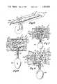
- FIG. 1is a top, plan view of one preferred embodiment of the penile prosthesis of this invention
- FIG. 2is a fragmentary, section view showing the valve chamber and interconnecting portions of the penile prosthesis cylinder, taken along lines 2--2 of FIG. 1;
- FIG. 3is a section view of the valve mechanism of FIG. 1 taken along lines 3--3 of FIG. 2;
- FIG. 4is a section view of the valve mechanism taken at the same location on FIG. 2 as is the view for FIG. 3, but showing the valve seat displaced to open the valve;
- FIG. 5is a side elevation view showing the penile prosthesis of FIG. 1 implanted in a male with the prosthesis in a nonerect condition and wherein portions of the male anatomy including the penis and scrotum are shown in phantom;
- FIG. 6is a side elevation view showing an alternative embodiment of the penile prosthesis as implanted in a male patient, with the prosthesis in an erect condition;
- FIG. 7is a section view showing the valve mechanism of the embodiment of the penile prosthesis depicted in FIG. 6, taken along lines 7--7 of FIG. 6;
- FIG. 8is a section view showing the same valve mechanism as depicted in FIG. 7, but with the valves depicted in their pumping stroke positions with fluid flowing from the pump to the distal end of the implant cylinder;
- FIG. 9also shows the same cross section view of the valve assembly as depicted in FIGS. 7 and 8, but with the valve assembly actuated to the position which it will assume to permit reverse flow of fluid from the distal cylinder to the fluid reservoir.
- FIGS. 1 through 5one preferred embodiment of the implantable penile prosthesis.
- the prosthesisis comprised of an elongated cylinder generally indicated by reference numeral 1.
- Cylinder 1is adapted to be implanted within the patient's penis, and preferably within one of the corpus cavernosum of the penis.
- Cylinder 1is comprised of a distal end section 2 and a proximal or root end section 4 separated by a valve section generally indicated by reference numeral 6.
- Distal end section 2is flexible and is adapted for implantation within the pendulous segment of the penis. To that end, distal section 2 is tapered along its length from a point adjacent its end near valve section 6 towards its distal tip.
- tubular prosthetic insert 1is generally referred to as a cylinder, it is to be understood that the distal end section 2 of the cylinder is preferably tapered as described herein.
- Distal end section 2is formed from a medical grade, biocompatible material which will permit it to flex and bend, whereby the penis may assume a bent, nonerect condition as shown in FIG. 5; however, the construction of distal section 2 is such that it will be impervious to fluid, and will rigidize upon being filled with a pressurizing fluid so as to permit the penis to assume an erected state.
- distal section 2 and proximal section 4 of the implant device 1are preferably formed from the same material joined together within valve section 6 at a sealed joint as by gluing to form a continuous tubular implant device 1.
- Proximal, root section 4 of the implant deviceis formed to provide a fluid reservoir chamber indicated by reference numeral 12 in FIG. 2.
- the reservoir chamber for pressurizing fluidis self-contained within the body of generally cylindrical prosthetic implant device 1.
- proximal reservoir chamber section 4 of implant 1will be positioned in the root segment of a corpus cavernosum. This location ensures the accessibility of reservoir chamber proximal section 4 for manual manipulation when it also serves as a pump as hereinafter set forth.
- valve block 14which may be made of hard rubber, such as medical grade silicone.
- valve block 14is positioned within cylinder 1 between fluid reservoir chamber 12 and distal end section 2 of implant device 1. It is formed to include a valve seat 16 with which a valve poppet or element 18 cooperates to provide a fluid flow control function between reservoir chamber 12 and distal end section 2.
- Valve poppet 18is connected by a stem 20 to a valve head 22.
- a coil spring 24is positioned as shown between annular shoulder 26 of valve block 14 and valve head 22 so as to normally urge valve poppet 18 to the left as viewed in FIG. 2 in a closing position against seat 16.
- Valve block 14is hollow internally so as to provide a chamber accomodating the aforesaid valve components.
- valve section 6 and the joint between cylinder sections 2 and 4 of the implant cylinder 1are preferably reinforced and sealed by a band or ring 28 made of the same silicone or polyurethane material of which cylinder 1 is constructed.
- a charging tube 30extends through reinforcing band 28 and the wall 1a of cylinder 1 surrounding valve block 14 and connects with an internal flow passage 32. Tube 30 serves for initially charging fluid into cylinder 1 for containment within reservoir chamber 12 and distal end section 2.
- the fluid with which cylinder 1 is chargedwill be a biocompatible, preferably radiopaque liquid, such as a saline solution which is noncompressible.
- a one piece stiffener generally indicated by reference numeral 34is positioned within the walls of cylinder 1 defining proximal, root section 4 forming reservoir chamber 12.
- Stiffener 34is preferably made from stainless steel and includes a rod 36 extending between a rounded end 35 and a continuous skirt head comprised of a conical segment 40 and a cylindrical skirt 38.
- Skirt 38is imbedded within the rubber forming valve block 14 and is apertured as shown for secure retention within the silicone rubber from which valve block 14 is molded.
- the opposite, rounded end 35 of stiffener 34bears against the extreme, proximal end of the root section 4 of implant cylinder 1.
- Apertures 42 formed in the conical segment 40 of stiffener 34permit unimpeded fluid flow from reservoir chamber 12 into the valve chamber formed within valve block 14, and thence into distal end section 2 through valve seat or port 16.
- Stiffener 34supports the flexible walls forming the proximal, reservoir portion 4 of cylinder 1 at all times. The strength and rigidity which stiffener 34 lends to proximal section 4 of the implant device particularly aids in the insertion of proximal section 4 within the root end of the corpora cavernosa of a male patient at the location shown in FIG. 5.
- proximal root section 4 of the implant cylinder 1which serves as reservoir chamber 12 also functions as the pump means.
- the walls of cylinder 1 defining proximal section 4are resiliently compressible inwardly.
- cylinder 1is adapted to be surgically implanted within the corpus cavernosum of the penis.
- the corpora cavernosa regions of the penisare first dilated, as by the insertion of a metal rod through the incision to displace the erectile tissue and create a space for the subsequent insertion of the prosthetic cylinders 1.
- distal end section 2will extend within the pendulous portion of the penis
- proximal section 4 of the cylinderwill extend into the root end of the corpora cavernosa as shown in FIG. 5.
- Proximal section 4comprising the combined fluid reservoir and pump will be located within the root end of the corpora cavernosa at the location where it may be subjected to compression and pumping action by the application of manual pressure to the patient's perineal tissue.
- FIG. 3illustrates the condition of the valve assembly in its normal, rest condition free from the application of any such squeezing pressure.
- the vertical deformation of valve seat 16 as illustrated in FIG. 4results in the forming of openings 44 adjacent the top and bottom of valve poppet 18. Fluid flows from distal end section 2 of cylinder 1 through openings 44 back into reservoir chamber 12, thereby depressurizing distal end section 2 and causing it to collapse to the condition shown in FIG. 5. This permits the penis to return to the nonerect state of FIG. 5.
- valve section 6 of the penile prosthesisis positioned along cylinder 1 at such a location that it will be located substantially as shown in FIG. 5 adjacent the base end of the penis and just inwardly from the body plane of the patient where it will be accessible to squeezing pressure applied to the skin adjacent the base of the penis.
- the implantable prosthetic cylinder 1is substantially identical to that illustrated in FIGS. 1 and 2.
- the implantable prosthetic cylindercomprises a distal end section 2 which is pressurizable to assume a rigid condition, a proximal, root section 4 which serves as a fluid reservoir chamber 12, and a valve section 6 which may be conveniently located between the distal and root cylinder sections 2 and 4.
- a separate elastomeric bulb 46is employed as a pump device.
- Bulb 46is sized to fit conveniently within the scrotal sac of the patient as illustrated in FIG.
- Valve block 52is molded from solid rubber, preferably medical grade silicone in the same manner as is valve block 14 of the embodiment shown in FIGS. 1 and 2. Valve block 52 may also be located within cylinder 1 between reservoir chamber 12 of proximal section 4 and distal section 2 of the implant cylinder for convenient connection with pump bulb 46 through tube 48. As with the embodiment of FIGS.
- valve section 6may be reinforced by a band or ring 28 made of the same silicone or polyurethane material of which cylinder 1 is constructed.
- a stiffener 34 of the same shape and construction as illustrated and described above with respect to FIGS. 1 and 2may also preferably be utilized to lend rigidity and strength to proximal, flexible wall reservoir section 4 of implant cylinder 1. Stiffener 34 is affixed to rubber valve block 52 and positioned within proximal section 4 of the implant cylinder in the same manner as described above with respect to FIGS. 1 and 2.
- pump bulb 46Since the reservoir chamber 12 for the pressurizing fluid is formed within proximal section 4 of the implant cylinder, pump bulb 46 need only function as a fluid transfer pump. Accordingly, pump bulb 46 is of a relatively small size, and may be implanted within the scrotal sac as shown in FIG. 6 without unduly interfering with bodily organs contained therein or causing discomfort to the patient. Pump bulb 46 is in fluid flow communication with reservoir chamber 12 and distal section 2 of the implant cylinder through conduit tube 48 and valve chamber 50. The flow of fluid between these components of the system is controlled by a valve mechanism positioned within valve block 52. A first check valve comprised of a valve seat 54 formed within valve block 50 and a valve poppet 56 controls flow between fluid reservoir chamber 12 and pump bulb 46.
- a valve stem 58is slidably positioned within U-shaped poppet element 56 in slidable relation thereto.
- Stem 58is normally urged to the left as viewed in FIG. 7 against poppet 56 to hold it in a closed position against valve seat 54 by a coil spring 60 bearing against stem collar 62.
- the opposite end of spring 60bears against an annular shoulder 64 formed on valve block 52. Pressure differentials created across valve seat 54 by the pumping action of bulb 46 permit valve poppet 56 to be unseated only so as to permit fluid flow in a direction from reservoir chamber 12 through valve chamber 50 to pump bulb 46.
- valve seat 66controls the flow of fluid between valve chamber 50 and distal end section 2 of the implant cylinder.
- Valve seat 66preferably takes the form of a ring molded integrally with valve block 52 and protruding laterally from one side thereof as shown in FIG. 7.
- Valve head 68is normally held in seating engagement therewith by coil spring 60.
- Valve stem extension 70 on which valve head 68 is formedmay be molded integrally with valve stem 58 or securely affixed thereto for shifting movement therewith in a longitudinal direction.
- the valve assemblyfurther includes means for manually manipulating the first and second check valves 54-56 and 66-68 to open positions to permit fluid flow from distal end section 2 back into fluid reservoir chamber 12.
- an elongated, flexible connector 72is attached between valve stem 58 and stretchable tube 48.
- Flexible connection 72may take the form of a dacron cord or a medical suture. At its upper end it is affixed to a sleeve 74 received within a recess 76 formed in the collar 62 of valve stem 58.
- the bottom end of connector cord 72may be looped through the side wall of stretchable tube 48 and secured thereto by a knot as illustrated in FIGS. 7-9.
- a retention band 78is affixed around stretchable tube 48 over the location of attachment of cord 72 thereto in order to secure and hold the bottom end of cord 72 in place.
- Band 78may also be a ring of silicone rubber.
- FIGS. 6-9The prosthetic device illustrated in FIGS. 6-9 is implanted in substantially the same way as that described above with respect to the embodiment of FIGS. 1-5.
- Distal end section 2 of the implant cylinder 1will be contained within one of the corpus cavernosum of the penis, and proximal, fluid reservoir section 4 thereof will be located within the root end of one of the corpus cavernosum.
- Pump bulb 46is located within the scrotal sac as stated above. When the patient desires to achieve an erection, pumping action is applied to bulb 46 by applying squeezing pressure thereto through the scrotal sac. Repetitive, squeezing manipulation of pump bulb 46 in that manner will have the effect of transfering fluid from reservoir chamber 12 to distal end section 2 of the implant cylinder.
- valve poppet 56will be drawn out of seating engagement with seat 54 and will shift to the right as viewed in FIG. 7 along valve stem 58. This permits fluid to flow from reservoir chamber 12, through valve chamber 52 and into pump bulb 46 through conduit 48.
- the pressurized fluid within valve chamber 50will force poppet 56 back to the left against seat 54.
- the pressurized fluid acting on the underside of valve head 68will shift it to the right as viewed in FIG. 8, overcoming spring pressure 60, to open valve seat 66. Fluid is thus permitted to flow under pressure into distal end section 2 of the implant cylinder. This causes flexible distal section 2 to elongate and rigidize as shown in FIG. 6 thereby producing an erection.
- distal end section 2 of the implant cylinder 1is made of flexible, medical grade material which will permit it to collapse and bend to the condition shown in FIG. 5.
- Distal end section 2is also inflatable to the extent that it may be rigidized in a straight condition for producing an erection as illustrated in FIG. 6.
- inflatableas used herein is intended to mean a penile prosthesis of the type having a distal end section 2 which is flexibly bendable to permit the penis to assume a flaccid state, but which rigidizes upon being pressurized to produce an erection.
- the implant cylinder as disclosed hereinmay be made of silicone or polyurethane so that distal end section 2 is expandable in girth and length; or it may be made of materials which permit distal end section 2 to distend only to a limited extent.
- the latter type of cylinderhas the advantage that it can be rigidized with a lesser volume of fluid.
- Such a limited distensible cylindercan be made of silicone or polyurethane reinforced by dacron fibers. The fiber reinforcing limits the ability of distal section 2 to distend.
- the fiber reinforced implant cylindermay be made in the same manner as the limited distensible fluid chamber of the implant cylinder described in the aforesaid copending U.S. application Ser. No. 108,124.
- the implantable prosthetic cylinder as disclosed herein with its self-contained fluid reservoir chamber at one end thereofwill greatly simplify surgical implant procedures. No separate, reservoir chamber containing fluid is required to be implanted within the patient at a location remote from the penis.
- the embodiment illustrated and described with respect to FIGS. 1-5also eliminates the need for a separate pump bulb by utilizing the proximal reservoir chamber section of the implant cylinder as the pumping device.
- the utilization of a fluid reservoir chamber formed within the implant cylinder, and the containment of the valve mechanism within the implant cylinder itselfpermits the separate pump bulb implanted within the scrotal sac to be of relatively small size.
Landscapes
- Health & Medical Sciences (AREA)
- Reproductive Health (AREA)
- Cardiology (AREA)
- Oral & Maxillofacial Surgery (AREA)
- Transplantation (AREA)
- Engineering & Computer Science (AREA)
- Biomedical Technology (AREA)
- Heart & Thoracic Surgery (AREA)
- Vascular Medicine (AREA)
- Life Sciences & Earth Sciences (AREA)
- Animal Behavior & Ethology (AREA)
- General Health & Medical Sciences (AREA)
- Public Health (AREA)
- Veterinary Medicine (AREA)
- Prostheses (AREA)
Abstract
Description
Claims (12)
Priority Applications (8)
| Application Number | Priority Date | Filing Date | Title |
|---|---|---|---|
| US06/264,202US4383525A (en) | 1979-12-28 | 1981-05-15 | Implantable penile prosthetic cylinder with inclusive fluid reservoir |
| US06/373,481US4407278A (en) | 1981-05-15 | 1982-05-03 | Penile prosthesis with improved fluid control |
| EP82302438AEP0065853B1 (en) | 1981-05-15 | 1982-05-13 | Penile prosthesis with improved fluid control |
| DE8282302438TDE3266329D1 (en) | 1981-05-15 | 1982-05-13 | Penile prosthesis with improved fluid control |
| JP8136282AJPS5924824B2 (en) | 1981-05-15 | 1982-05-14 | implantable artificial penis |
| ES512198AES512198A0 (en) | 1981-05-15 | 1982-05-14 | "IMPROVEMENTS IN IMPLANTABLE PENIAL PROSTHESES". |
| CA000402945ACA1185403A (en) | 1981-05-15 | 1982-05-14 | Penile prosthesis with improved fluid control |
| US07/241,826US5704895A (en) | 1979-12-28 | 1988-09-06 | Implantable penile prosthetic cylinder with inclusive fluid reservoir |
Applications Claiming Priority (2)
| Application Number | Priority Date | Filing Date | Title |
|---|---|---|---|
| US06/108,124US4267829A (en) | 1979-04-11 | 1979-12-28 | Penile prosthesis |
| US06/264,202US4383525A (en) | 1979-12-28 | 1981-05-15 | Implantable penile prosthetic cylinder with inclusive fluid reservoir |
Related Parent Applications (1)
| Application Number | Title | Priority Date | Filing Date |
|---|---|---|---|
| US06/108,124Continuation-In-PartUS4267829A (en) | 1979-04-11 | 1979-12-28 | Penile prosthesis |
Related Child Applications (2)
| Application Number | Title | Priority Date | Filing Date |
|---|---|---|---|
| US06/373,481Continuation-In-PartUS4407278A (en) | 1981-05-15 | 1982-05-03 | Penile prosthesis with improved fluid control |
| US49436083AContinuation | 1979-12-28 | 1983-05-13 |
Publications (1)
| Publication Number | Publication Date |
|---|---|
| US4383525Atrue US4383525A (en) | 1983-05-17 |
Family
ID=22320452
Family Applications (3)
| Application Number | Title | Priority Date | Filing Date |
|---|---|---|---|
| US06/108,124Expired - LifetimeUS4267829A (en) | 1979-04-11 | 1979-12-28 | Penile prosthesis |
| US06/264,202Expired - LifetimeUS4383525A (en) | 1979-12-28 | 1981-05-15 | Implantable penile prosthetic cylinder with inclusive fluid reservoir |
| US07/241,826Expired - Fee RelatedUS5704895A (en) | 1979-12-28 | 1988-09-06 | Implantable penile prosthetic cylinder with inclusive fluid reservoir |
Family Applications Before (1)
| Application Number | Title | Priority Date | Filing Date |
|---|---|---|---|
| US06/108,124Expired - LifetimeUS4267829A (en) | 1979-04-11 | 1979-12-28 | Penile prosthesis |
Family Applications After (1)
| Application Number | Title | Priority Date | Filing Date |
|---|---|---|---|
| US07/241,826Expired - Fee RelatedUS5704895A (en) | 1979-12-28 | 1988-09-06 | Implantable penile prosthetic cylinder with inclusive fluid reservoir |
Country Status (4)
| Country | Link |
|---|---|
| US (3) | US4267829A (en) |
| CA (1) | CA1151804A (en) |
| DE (1) | DE3048591A1 (en) |
| FR (1) | FR2472376A1 (en) |
Cited By (53)
| Publication number | Priority date | Publication date | Assignee | Title |
|---|---|---|---|---|
| US4449520A (en)* | 1982-09-02 | 1984-05-22 | Palomar Juan M | Penile prosthesis device |
| WO1984003038A1 (en)* | 1983-02-14 | 1984-08-16 | Robert E Trick | Implantable penile erectile system |
| FR2550935A1 (en)* | 1983-08-26 | 1985-03-01 | Fischell Robert | METHOD AND DEVICE FOR OBTAINING THE PENIS ERECTION IN A MAN |
| US4550719A (en)* | 1981-08-04 | 1985-11-05 | Medical Engineering Corporation | Implantable penile erectile system |
| US4559931A (en)* | 1983-03-21 | 1985-12-24 | Fischell Robert | Manually actuated fully implantable penile erection device |
| US4574792A (en)* | 1981-09-24 | 1986-03-11 | Medical Engineering Corporation | Penile erectile system |
| US4590927A (en)* | 1985-02-25 | 1986-05-27 | American Medical Systems, Inc. | Unitary, inflatable penile prosthesis system |
| US4594997A (en)* | 1984-11-13 | 1986-06-17 | Hakky Said I | Self actuated penile implant |
| US4602621A (en)* | 1984-12-18 | 1986-07-29 | Hakky Said I | Manually actuated, self contained penile implant |
| US4604994A (en)* | 1985-06-24 | 1986-08-12 | Repro-Med Systems, Inc. | Implantable medical prosthesis for obviating male impotency |
| US4622958A (en)* | 1984-12-12 | 1986-11-18 | Medical Engineering Corporation | Penile implant with accumulator |
| US4682589A (en)* | 1980-05-15 | 1987-07-28 | Medical Engineering Corporation | Penile prosthesis |
| US4711231A (en)* | 1986-11-03 | 1987-12-08 | Aaron N. Finegold | Implantable prosthesis system |
| US4726360A (en)* | 1986-07-17 | 1988-02-23 | Medical Engineering Corporation | Penile prosthesis |
| US4773403A (en)* | 1987-08-17 | 1988-09-27 | Medical Engineering Corporation | Penile prosthesis |
| US4823779A (en)* | 1987-05-15 | 1989-04-25 | Medical Engineering Corporation | Penile implant with compensator |
| US4881530A (en)* | 1988-01-19 | 1989-11-21 | Medical Engineering Corporation | Penile prosthesis |
| US4895139A (en)* | 1988-08-29 | 1990-01-23 | American Medical Systems, Inc. | Inflatable penile prosthesis with bend release valve |
| US4898158A (en)* | 1987-05-15 | 1990-02-06 | Medical Engineering Corporation | Penile implant with improved pressure relief valve |
| US4917110A (en)* | 1986-07-17 | 1990-04-17 | Medical Engineering Corporation | Penile prosthesis |
| US4995380A (en)* | 1989-11-07 | 1991-02-26 | Medical Engineering Corporation | Penile prosthesis |
| US5851176A (en)* | 1996-07-29 | 1998-12-22 | Mentor Corporation | Pressure-responsive lockout valve and method of use |
| US6443887B1 (en) | 2000-12-27 | 2002-09-03 | American Medical Systems Inc. | Switch based spontaneous inflation inhibitor in a pump for an inflation prosthesis |
| US6533719B2 (en) | 2000-12-27 | 2003-03-18 | Ams Research Corporation | Diaphragm based spontaneous inflation inhibitor in a pump for an inflatable prosthesis |
| US6723042B2 (en) | 2000-12-27 | 2004-04-20 | Ams Research Corporation | Penile pump with side release mechanism |
| US6730017B2 (en) | 2000-12-27 | 2004-05-04 | Ams Research Corporation | Pressure based spontaneous inflation inhibitor with penile pump improvements |
| US20040102677A1 (en)* | 2000-09-11 | 2004-05-27 | Vincent Frering | Method and device for controlling the blowing of an inflatable prosthetic envelope |
| US20040138523A1 (en)* | 2002-12-02 | 2004-07-15 | Ams Research Corporation | Implantable pump |
| US20040220447A1 (en)* | 2003-03-10 | 2004-11-04 | Morningstar Randy L. | Implantable penile prosthesis pump |
| US20050014993A1 (en)* | 2003-06-06 | 2005-01-20 | Mische Hans A. | Inflatable penile prosthesis with volume displacement materials and devices |
| US20050043581A1 (en)* | 2003-04-25 | 2005-02-24 | Ling Jeremy J. | Penile prosthesis with improved tubing junction |
| US20050075534A1 (en)* | 2003-10-02 | 2005-04-07 | Ams Research Corporation | Penile prosthesis devices and methods |
| US20050113638A1 (en)* | 2003-10-02 | 2005-05-26 | Kuyava Charles C. | Implantable penile prosthesis pump |
| US20060135845A1 (en)* | 2004-12-17 | 2006-06-22 | Ams Research Corporation | Implantable penile prosthesis pump |
| WO2007096354A1 (en)* | 2006-02-21 | 2007-08-30 | Didier Tytgadt | Variable volume body implant |
| US20090105530A1 (en)* | 2007-10-23 | 2009-04-23 | Ams Research Corporation | Corrugated Inflatable Penile Prosthesis Cylinder |
| US20090105818A1 (en)* | 2007-10-23 | 2009-04-23 | Ams Research Corporation | Malleable Prosthesis with Enhanced Concealability |
| US20090132043A1 (en)* | 2007-11-15 | 2009-05-21 | George Stephanie A | Prosthesis with Bladder that Adjusts Girth |
| US20100082057A1 (en)* | 2008-09-30 | 2010-04-01 | Borkon William D | Variable rigidity vaginal dilator and use thereof |
| US20100160722A1 (en)* | 2008-12-23 | 2010-06-24 | Ams Research Corporation | Penile prosthesis implantation device |
| US20100160723A1 (en)* | 2008-12-23 | 2010-06-24 | Kuyava Charles C | System to transport components of implantable penile prostheses |
| US7946975B2 (en) | 2005-04-08 | 2011-05-24 | Ams Research Corporation | Fluid reservoir for penile implant devices |
| US20110201880A1 (en)* | 2010-02-12 | 2011-08-18 | Fogarty Terence M | Inflatable penile prosthesis with spool valve |
| US8109870B2 (en) | 2006-11-10 | 2012-02-07 | Ams Research Corporation | Inflatable penile prosthesis bypass valve noise reduction |
| US8123674B2 (en) | 2007-11-12 | 2012-02-28 | Ams Research Corporation | Corrugated expansion-constraining sleeve for an inflatable penile prosthesis cylinder |
| US9084678B2 (en) | 2012-01-20 | 2015-07-21 | Ams Research Corporation | Automated implantable penile prosthesis pump system |
| US9474610B2 (en) | 2010-12-21 | 2016-10-25 | Boston Scientific Scimed, Inc. | Adjustable length rear tip extender for penile prosthesis |
| US9554937B2 (en) | 2014-06-16 | 2017-01-31 | Coloplast A/S | Penile prosthetic pump having an inlet valve with a lockout flange |
| US20170095334A1 (en)* | 2014-12-04 | 2017-04-06 | Coloplast A/S | Implantable penile prosthetic having a base expandable by liquid inflation |
| US9649217B2 (en) | 2014-07-08 | 2017-05-16 | Coloplast A/S | Implantable penile prosthetic lockout valve assembly |
| US9987136B2 (en) | 2016-09-09 | 2018-06-05 | Coloplast A/S | Penile prosthetic pump with an inflation assembly including a rotary valve |
| US10729546B2 (en) | 2017-02-02 | 2020-08-04 | Coloplast A/S | Inflatable penile prosthetic system |
| US20230285150A1 (en)* | 2022-03-09 | 2023-09-14 | Coloplast A/S | Penile prosthesis pump having a deflate valve assembly including a grooved valve stem disposed in a sleeve |
Families Citing this family (104)
| Publication number | Priority date | Publication date | Assignee | Title |
|---|---|---|---|---|
| WO1980000302A1 (en)* | 1978-08-02 | 1980-03-06 | S Hakky | Improvements in surgical implants |
| US4267829A (en)* | 1979-04-11 | 1981-05-19 | American Medical Systems, Inc. | Penile prosthesis |
| US4411261A (en)* | 1980-05-15 | 1983-10-25 | Medical Engineering Corporation | Semi-rigid penile implant |
| US4360010A (en)* | 1980-05-15 | 1982-11-23 | Medical Engineering Corporation | Penile prosthesis |
| US4378792A (en)* | 1980-05-15 | 1983-04-05 | Medical Engineering Corporation | Penile prosthesis |
| US4353360A (en)* | 1980-10-31 | 1982-10-12 | Medical Engineering Corporation | Penile erectile system |
| FR2508309A2 (en)* | 1981-06-29 | 1982-12-31 | Subrini Louis | Semi-rigid implantable penile prostheses - has cylindrical shaft joined to part-spherical tip by frusto=conical portion |
| US4399811A (en)* | 1981-08-04 | 1983-08-23 | Medical Engineering Corporation | Implantable penile erectile system |
| US4369771A (en)* | 1981-09-24 | 1983-01-25 | Medical Engineering Corporation | Penile erectile system |
| US4457335A (en)* | 1981-09-24 | 1984-07-03 | Medical Engineering Corporation | Penile erectile system |
| US4791917A (en)* | 1981-10-22 | 1988-12-20 | Medical Engineering Corporation | Penile prosthesis |
| US4399812A (en)* | 1981-12-31 | 1983-08-23 | Whitehead Edgar D | Penile prosthetic device |
| US4665903A (en)* | 1981-12-31 | 1987-05-19 | Whitehead Edgar D | Penile prosthetic device |
| US4566446A (en)* | 1983-04-08 | 1986-01-28 | Mentor Corporation | Penile prosthesis device |
| US4522198A (en)* | 1983-04-18 | 1985-06-11 | Dacomed Corporation | Penile prosthesis |
| US4517967A (en)* | 1983-04-18 | 1985-05-21 | Dacomed Corporation | Penile prosthesis |
| US4572168A (en)* | 1983-12-20 | 1986-02-25 | Fischell Robert | Fully implantable vapor pressure actuated penile erection device and method |
| US4730607A (en)* | 1984-08-20 | 1988-03-15 | Fischell Robert | Stiffener cylinder for an inflatable penile erection device |
| DE3529613A1 (en)* | 1984-08-20 | 1986-02-27 | Robert Ellentuch Silver Spring Fischell, Md. | REINFORCEMENT CYLINDER FOR AN INFLATABLE PENIS READING DEVICE |
| US4651721A (en)* | 1985-04-10 | 1987-03-24 | American Medical Systems, Inc. | Penile prosthesis system |
| US4881531A (en)* | 1986-11-21 | 1989-11-21 | Dacomed Corporation | Position stable segmented column penile prosthesis |
| GB2198358B (en)* | 1986-12-12 | 1991-07-24 | Bristol Myers Co | Filling port |
| US4852555A (en)* | 1987-12-02 | 1989-08-01 | Medical Engineering Corporation | Inflatable penile prosthesis |
| US4875472A (en)* | 1987-12-10 | 1989-10-24 | American Medical Systems, Inc. | Flat coil spring penile prosthesis |
| US5048510A (en)* | 1988-08-29 | 1991-09-17 | American Medical Systems, Inc. | Inflatable penile prosthesis with satellite reservoir |
| DE3918955A1 (en)* | 1989-06-09 | 1989-12-21 | Ringer Michael | Technical simulation of the biological muscle principle as a technical muscle. Robot resembling an animal or a human being and having technical muscles. Parts of this robot as prostheses. Further applications of the muscle: as lifting and tensioning device, as muscle motor, for positioning of an object by several muscles, as adjustment means for the range of spring |
| US5010882A (en)* | 1989-11-13 | 1991-04-30 | American Medical Systems, Inc. | Implantable penile prosthesis |
| FR2654922B1 (en)* | 1989-11-28 | 1994-07-01 | Subrini Louis | PENIAN FILL IMPLANT. |
| DE9001508U1 (en)* | 1990-02-09 | 1990-04-12 | ESKA Kunststofftechnik GmbH & Co. vormals Walter Koss, 6222 Geisenheim | Implantable penile prosthesis |
| US5069201A (en)* | 1990-04-20 | 1991-12-03 | Zinner Norman R | Penile prosthesis and method |
| US5112295A (en)* | 1990-04-20 | 1992-05-12 | Zinner Norman R | Penile prosthesis and method |
| US5167611A (en)* | 1991-07-22 | 1992-12-01 | Mentor Corporation | Penile implant with lengthening cylinder |
| US5263981A (en)* | 1992-04-24 | 1993-11-23 | American Medical Systems, Inc. | Implantable penile prosthesis |
| KR960015796B1 (en)* | 1993-09-28 | 1996-11-21 | 임승현 | Penis |
| US6102929A (en)* | 1994-09-15 | 2000-08-15 | Mentor Urology, Inc. | Prostatic tissue expander |
| US5868140A (en)* | 1995-11-07 | 1999-02-09 | Cti Corporation | Surgical method and apparatus for implantation of a testicular prosthetic device |
| US5895424A (en)* | 1996-11-12 | 1999-04-20 | Mentor Corporation | Prosthesis having an alignment indicator and method of using same |
| IL128261A0 (en)* | 1999-01-27 | 1999-11-30 | Disc O Tech Medical Tech Ltd | Expandable element |
| WO2004110300A2 (en)* | 2001-07-25 | 2004-12-23 | Disc Orthopaedic Technologies Inc. | Deformable tools and implants |
| EP1905392B1 (en)* | 1997-03-07 | 2011-05-18 | Kyphon SÀRL | System for percutaneous bone and spinal stabilization, fixation and repair |
| US7621950B1 (en) | 1999-01-27 | 2009-11-24 | Kyphon Sarl | Expandable intervertebral spacer |
| DE19903246B4 (en)* | 1999-01-27 | 2005-11-24 | Dieter Riemer | Erection device for a human penis |
| US6346492B1 (en) | 1999-05-06 | 2002-02-12 | American Medical Systems, Inc. | Fabric for use in prosthetics |
| US6475137B1 (en)* | 2000-10-13 | 2002-11-05 | James Elist | Subcutaneous penile implant |
| US6579230B2 (en)* | 2001-06-15 | 2003-06-17 | Impetus Ltd. | Penile prosthesis and method of implantation |
| US7419949B2 (en)* | 2001-07-16 | 2008-09-02 | Novo Noridsk Healthcare A/G | Single-dose administration of factor VIIa |
| US20030097178A1 (en)* | 2001-10-04 | 2003-05-22 | Joseph Roberson | Length-adjustable ossicular prosthesis |
| US7965719B2 (en)* | 2002-12-11 | 2011-06-21 | Broadcom Corporation | Media exchange network supporting multiple broadband network and service provider infrastructures |
| ES2545328T3 (en) | 2003-03-14 | 2015-09-10 | Depuy Spine, Inc. | Bone cement hydraulic injection device in percutaneous vertebroplasty |
| US8066713B2 (en) | 2003-03-31 | 2011-11-29 | Depuy Spine, Inc. | Remotely-activated vertebroplasty injection device |
| US8415407B2 (en) | 2004-03-21 | 2013-04-09 | Depuy Spine, Inc. | Methods, materials, and apparatus for treating bone and other tissue |
| US20070032567A1 (en)* | 2003-06-17 | 2007-02-08 | Disc-O-Tech Medical | Bone Cement And Methods Of Use Thereof |
| US7052546B1 (en)* | 2003-08-28 | 2006-05-30 | Cape Simulations, Inc. | High-purity crystal growth |
| US8579908B2 (en)* | 2003-09-26 | 2013-11-12 | DePuy Synthes Products, LLC. | Device for delivering viscous material |
| CN100542503C (en)* | 2003-10-02 | 2009-09-23 | Ams研究公司 | Reservoir for penile implant device and method of manufacture |
| KR101131148B1 (en)* | 2003-10-02 | 2012-03-28 | 에이엠에스 리써치 코오포레이션 | Fluid reservoirs for penile implant devices and methods of manufacturing |
| CN101065080B (en) | 2004-07-30 | 2021-10-29 | 德普伊新特斯产品有限责任公司 | Materials and Instruments for Manipulating Bone and Other Tissues |
| US7317331B2 (en)* | 2004-11-08 | 2008-01-08 | Tabula, Inc. | Reconfigurable IC that has sections running at different reconfiguration rates |
| US9381024B2 (en)* | 2005-07-31 | 2016-07-05 | DePuy Synthes Products, Inc. | Marked tools |
| US9918767B2 (en) | 2005-08-01 | 2018-03-20 | DePuy Synthes Products, Inc. | Temperature control system |
| US8360629B2 (en)* | 2005-11-22 | 2013-01-29 | Depuy Spine, Inc. | Mixing apparatus having central and planetary mixing elements |
| CN101351173B (en)* | 2005-12-19 | 2011-01-26 | 康乐保公司 | Pump with one-touch release |
| AU2007297097A1 (en) | 2006-09-14 | 2008-03-20 | Depuy Spine, Inc. | Bone cement and methods of use thereof |
| US8950929B2 (en) | 2006-10-19 | 2015-02-10 | DePuy Synthes Products, LLC | Fluid delivery system |
| US20100274246A1 (en)* | 2007-05-10 | 2010-10-28 | Oren Globerman | Expandable intramedullary nail for small bone fixation |
| EP2180850B1 (en)* | 2007-07-25 | 2018-11-21 | Depuy Spine, Inc. | Expandable bone filler materials and methods of using same |
| WO2009094431A2 (en) | 2008-01-23 | 2009-07-30 | Ams Research Corporation | Inflatable medical implant system |
| US8678008B2 (en)* | 2008-07-30 | 2014-03-25 | Ethicon, Inc | Methods and devices for forming an auxiliary airway for treating obstructive sleep apnea |
| US8556797B2 (en)* | 2008-07-31 | 2013-10-15 | Ethicon, Inc. | Magnetic implants for treating obstructive sleep apnea and methods therefor |
| US7922649B2 (en)* | 2008-08-08 | 2011-04-12 | Walch John R | Unitized penile erection system and tissue expander |
| KR20100019615A (en)* | 2008-08-11 | 2010-02-19 | 삼성전자주식회사 | Joint body and manufacturing method of the same |
| US8413661B2 (en) | 2008-08-14 | 2013-04-09 | Ethicon, Inc. | Methods and devices for treatment of obstructive sleep apnea |
| WO2010043228A1 (en)* | 2008-10-16 | 2010-04-22 | Coloplast A/S | Apparatus and method for manufacturing a penile cylinder having a reinforced tip |
| US8561616B2 (en) | 2008-10-24 | 2013-10-22 | Ethicon, Inc. | Methods and devices for the indirect displacement of the hyoid bone for treating obstructive sleep apnea |
| US8561617B2 (en) | 2008-10-30 | 2013-10-22 | Ethicon, Inc. | Implant systems and methods for treating obstructive sleep apnea |
| US8800567B2 (en) | 2008-12-01 | 2014-08-12 | Ethicon, Inc. | Implant systems and methods for treating obstructive sleep apnea |
| US8783258B2 (en) | 2008-12-01 | 2014-07-22 | Ethicon, Inc. | Implant systems and methods for treating obstructive sleep apnea |
| WO2010087768A1 (en)* | 2009-01-29 | 2010-08-05 | Milux Holding S.A. | A penile implant |
| US8371308B2 (en) | 2009-02-17 | 2013-02-12 | Ethicon, Inc. | Magnetic implants and methods for treating an oropharyngeal condition |
| US8307831B2 (en) | 2009-03-16 | 2012-11-13 | Ethicon, Inc. | Implant systems and methods for treating obstructive sleep apnea |
| US9877862B2 (en) | 2009-10-29 | 2018-01-30 | Ethicon, Inc. | Tongue suspension system with hyoid-extender for treating obstructive sleep apnea |
| US9326886B2 (en) | 2009-10-29 | 2016-05-03 | Ethicon, Inc. | Fluid filled implants for treating obstructive sleep apnea |
| US9974683B2 (en)* | 2009-10-30 | 2018-05-22 | Ethicon, Inc. | Flexible implants having internal volume shifting capabilities for treating obstructive sleep apnea |
| DK200970206A (en)* | 2009-11-16 | 2011-05-17 | Coloplast As | Penile prosthetic with anti-autoinflation mechanism |
| US8632488B2 (en)* | 2009-12-15 | 2014-01-21 | Ethicon, Inc. | Fluid filled implants for treating medical conditions |
| US8545393B2 (en)* | 2010-02-04 | 2013-10-01 | Coloplast A/S | Inflatable penile implant |
| US8016746B2 (en)* | 2010-02-03 | 2011-09-13 | Coloplast A/S | Inflatable penile implant |
| CN101940506B (en)* | 2010-08-12 | 2013-06-19 | 叶明� | Penis implant and preparation method thereof |
| US8257246B1 (en) | 2011-04-19 | 2012-09-04 | Coloplast A/S | Penile prosthetic system and pump having inlet valve with high velocity closure mechanism |
| US8905033B2 (en) | 2011-09-28 | 2014-12-09 | Ethicon, Inc. | Modular tissue securement systems |
| US9161855B2 (en) | 2011-10-24 | 2015-10-20 | Ethicon, Inc. | Tissue supporting device and method |
| US8973582B2 (en) | 2011-11-30 | 2015-03-10 | Ethicon, Inc. | Tongue suspension device and method |
| US10470760B2 (en) | 2011-12-08 | 2019-11-12 | Ethicon, Inc. | Modified tissue securement fibers |
| US9173766B2 (en) | 2012-06-01 | 2015-11-03 | Ethicon, Inc. | Systems and methods to treat upper pharyngeal airway of obstructive sleep apnea patients |
| EP3508174A1 (en)* | 2012-09-27 | 2019-07-10 | Boston Scientific Scimed, Inc. | Implantable penile prosthesis |
| US8795154B1 (en)* | 2013-07-03 | 2014-08-05 | Said I. Hakky | Propulsion inflatable penile implant |
| US8939889B1 (en)* | 2013-08-22 | 2015-01-27 | Coloplast A/S | Pump bulb for an implantable penile prosthetic |
| US11432929B2 (en) | 2015-12-31 | 2022-09-06 | Menova International, Inc. | Prosthesis for improved penis function |
| US9504573B1 (en) | 2015-12-31 | 2016-11-29 | James J. Elist | Prosthesis for improved penis function |
| US10813762B2 (en)* | 2017-09-26 | 2020-10-27 | Boston Scientific Scimed, Inc. | Inflatable penile prosthesis with reinforced cylinder |
| US10706744B2 (en)* | 2018-03-16 | 2020-07-07 | Coloplast A/S | Penile prosthesis demonstration tool |
| US11324596B2 (en) | 2018-07-19 | 2022-05-10 | Boston Scientific Scimed, Inc. | Inflatable penile prosthesis with reinforced cylinder |
| US11580884B2 (en) | 2019-05-10 | 2023-02-14 | Coloplast A/S | Anatomical teaching model |
| US11819412B2 (en)* | 2020-02-04 | 2023-11-21 | Coloplast A/S | Penile prostheses for treatment of erectile dysfunction |
Citations (5)
| Publication number | Priority date | Publication date | Assignee | Title |
|---|---|---|---|---|
| US3853122A (en)* | 1973-10-12 | 1974-12-10 | B Strauch | Method and device for achieving a penile erection |
| US3954102A (en)* | 1974-07-19 | 1976-05-04 | American Medical Systems, Inc. | Penile erection system and methods of implanting and using same |
| US4009711A (en)* | 1976-03-17 | 1977-03-01 | Uson Aurelio C | Penile prosthesis for the management of erectile impotence |
| US4201202A (en)* | 1978-09-25 | 1980-05-06 | Medical Engineering Corp. | Penile implant |
| US4267829A (en)* | 1979-04-11 | 1981-05-19 | American Medical Systems, Inc. | Penile prosthesis |
Family Cites Families (6)
| Publication number | Priority date | Publication date | Assignee | Title |
|---|---|---|---|---|
| US3987789A (en)* | 1975-10-28 | 1976-10-26 | American Medical Systems, Inc. | Malleable penile prosthesis |
| US4066073A (en)* | 1976-10-04 | 1978-01-03 | Medical Engineering Corporation | Composite rod penile implant |
| WO1980000302A1 (en)* | 1978-08-02 | 1980-03-06 | S Hakky | Improvements in surgical implants |
| US4235227A (en)* | 1978-11-08 | 1980-11-25 | Hideo Yamanaka | Artificial corpus cavernosum device |
| US4224934A (en)* | 1979-04-11 | 1980-09-30 | American Medical Systems, Inc. | Medical prosthetic pull valve and system for using same |
| US4318396A (en)* | 1980-05-15 | 1982-03-09 | Medical Engineering Corporation | Penile prosthesis |
- 1979
- 1979-12-28USUS06/108,124patent/US4267829A/ennot_activeExpired - Lifetime
- 1980
- 1980-12-23DEDE19803048591patent/DE3048591A1/enactiveGranted
- 1980-12-23CACA000367422Apatent/CA1151804A/ennot_activeExpired
- 1980-12-26FRFR8027605Apatent/FR2472376A1/enactiveGranted
- 1981
- 1981-05-15USUS06/264,202patent/US4383525A/ennot_activeExpired - Lifetime
- 1988
- 1988-09-06USUS07/241,826patent/US5704895A/ennot_activeExpired - Fee Related
Patent Citations (5)
| Publication number | Priority date | Publication date | Assignee | Title |
|---|---|---|---|---|
| US3853122A (en)* | 1973-10-12 | 1974-12-10 | B Strauch | Method and device for achieving a penile erection |
| US3954102A (en)* | 1974-07-19 | 1976-05-04 | American Medical Systems, Inc. | Penile erection system and methods of implanting and using same |
| US4009711A (en)* | 1976-03-17 | 1977-03-01 | Uson Aurelio C | Penile prosthesis for the management of erectile impotence |
| US4201202A (en)* | 1978-09-25 | 1980-05-06 | Medical Engineering Corp. | Penile implant |
| US4267829A (en)* | 1979-04-11 | 1981-05-19 | American Medical Systems, Inc. | Penile prosthesis |
Cited By (90)
| Publication number | Priority date | Publication date | Assignee | Title |
|---|---|---|---|---|
| US4682589A (en)* | 1980-05-15 | 1987-07-28 | Medical Engineering Corporation | Penile prosthesis |
| US4550719A (en)* | 1981-08-04 | 1985-11-05 | Medical Engineering Corporation | Implantable penile erectile system |
| US4574792A (en)* | 1981-09-24 | 1986-03-11 | Medical Engineering Corporation | Penile erectile system |
| US4449520A (en)* | 1982-09-02 | 1984-05-22 | Palomar Juan M | Penile prosthesis device |
| WO1984003038A1 (en)* | 1983-02-14 | 1984-08-16 | Robert E Trick | Implantable penile erectile system |
| US4559931A (en)* | 1983-03-21 | 1985-12-24 | Fischell Robert | Manually actuated fully implantable penile erection device |
| FR2550935A1 (en)* | 1983-08-26 | 1985-03-01 | Fischell Robert | METHOD AND DEVICE FOR OBTAINING THE PENIS ERECTION IN A MAN |
| US4594997A (en)* | 1984-11-13 | 1986-06-17 | Hakky Said I | Self actuated penile implant |
| US4622958A (en)* | 1984-12-12 | 1986-11-18 | Medical Engineering Corporation | Penile implant with accumulator |
| US4602621A (en)* | 1984-12-18 | 1986-07-29 | Hakky Said I | Manually actuated, self contained penile implant |
| US4590927A (en)* | 1985-02-25 | 1986-05-27 | American Medical Systems, Inc. | Unitary, inflatable penile prosthesis system |
| US4604994A (en)* | 1985-06-24 | 1986-08-12 | Repro-Med Systems, Inc. | Implantable medical prosthesis for obviating male impotency |
| US4917110A (en)* | 1986-07-17 | 1990-04-17 | Medical Engineering Corporation | Penile prosthesis |
| US4726360A (en)* | 1986-07-17 | 1988-02-23 | Medical Engineering Corporation | Penile prosthesis |
| US4711231A (en)* | 1986-11-03 | 1987-12-08 | Aaron N. Finegold | Implantable prosthesis system |
| US4823779A (en)* | 1987-05-15 | 1989-04-25 | Medical Engineering Corporation | Penile implant with compensator |
| US4898158A (en)* | 1987-05-15 | 1990-02-06 | Medical Engineering Corporation | Penile implant with improved pressure relief valve |
| US4773403A (en)* | 1987-08-17 | 1988-09-27 | Medical Engineering Corporation | Penile prosthesis |
| US4881530A (en)* | 1988-01-19 | 1989-11-21 | Medical Engineering Corporation | Penile prosthesis |
| US4895139A (en)* | 1988-08-29 | 1990-01-23 | American Medical Systems, Inc. | Inflatable penile prosthesis with bend release valve |
| US4995380A (en)* | 1989-11-07 | 1991-02-26 | Medical Engineering Corporation | Penile prosthesis |
| US5851176A (en)* | 1996-07-29 | 1998-12-22 | Mentor Corporation | Pressure-responsive lockout valve and method of use |
| US6171233B1 (en) | 1996-07-29 | 2001-01-09 | Mentor Corporation | Pressure-responsive lockout valve and method of use |
| US7282023B2 (en)* | 2000-09-11 | 2007-10-16 | Magnetic Developpement Medical | Method and device for controlling the inflation of an inflatable prosthetic envelope |
| US20040102677A1 (en)* | 2000-09-11 | 2004-05-27 | Vincent Frering | Method and device for controlling the blowing of an inflatable prosthetic envelope |
| US6533719B2 (en) | 2000-12-27 | 2003-03-18 | Ams Research Corporation | Diaphragm based spontaneous inflation inhibitor in a pump for an inflatable prosthesis |
| US20050250981A1 (en)* | 2000-12-27 | 2005-11-10 | Kuyava Charles C | Method of preventing inadvertent inflation of an inflatable prosthesis |
| US6730017B2 (en) | 2000-12-27 | 2004-05-04 | Ams Research Corporation | Pressure based spontaneous inflation inhibitor with penile pump improvements |
| US20030065249A1 (en)* | 2000-12-27 | 2003-04-03 | Kuyava Charles C. | Diaphragm based spontaneous inflation inhibitor in a pump for an inflatable prosthesis |
| US7438682B2 (en) | 2000-12-27 | 2008-10-21 | Ams Research Corporation | Pressure based spontaneous inflation inhibitor with penile pump improvements |
| US20090287042A1 (en)* | 2000-12-27 | 2009-11-19 | Ams Research Corporation | Penile Pump with Side Release Mechanism |
| US20040220448A1 (en)* | 2000-12-27 | 2004-11-04 | Henkel Gregory J | Pressure based spontaneous inflation inhibitor with penile pump improvements |
| US7350538B2 (en) | 2000-12-27 | 2008-04-01 | Ams Research Corporation | Method of preventing inadvertent inflation of an inflatable prosthesis |
| US6443887B1 (en) | 2000-12-27 | 2002-09-03 | American Medical Systems Inc. | Switch based spontaneous inflation inhibitor in a pump for an inflation prosthesis |
| US8276591B2 (en) | 2000-12-27 | 2012-10-02 | Ams Research Corporation | Diaphragm based spontaneous inflation inhibitor in a pump for an inflatable prosthesis |
| US6723042B2 (en) | 2000-12-27 | 2004-04-20 | Ams Research Corporation | Penile pump with side release mechanism |
| US6935847B2 (en) | 2000-12-27 | 2005-08-30 | Ams Research Corporation | Spontaneous inflation inhibitor for inflatable prosthesis |
| US20090084447A1 (en)* | 2000-12-27 | 2009-04-02 | Ams Research Corporation | Diaphragm Based Spontaneous Inflation Inhibitor in a Pump for an Inflatable Prosthesis |
| US7874978B2 (en) | 2002-12-02 | 2011-01-25 | Ams Research Corporation | Implantable pump |
| US6991601B2 (en) | 2002-12-02 | 2006-01-31 | Ams Research Corporation | Implantable pump |
| US20110087068A1 (en)* | 2002-12-02 | 2011-04-14 | Ams Research Corporation | Implantable Pump |
| US20050250982A1 (en)* | 2002-12-02 | 2005-11-10 | Kuyava Charles C | Implantable pump |
| US8062209B2 (en) | 2002-12-02 | 2011-11-22 | Ams Research Corporation | Implantable pump |
| US20040138523A1 (en)* | 2002-12-02 | 2004-07-15 | Ams Research Corporation | Implantable pump |
| US7244227B2 (en) | 2003-03-10 | 2007-07-17 | Ams Research Corporation | Implantable penile prosthesis pump |
| US20040220447A1 (en)* | 2003-03-10 | 2004-11-04 | Morningstar Randy L. | Implantable penile prosthesis pump |
| US7169103B2 (en) | 2003-04-25 | 2007-01-30 | Ams Research Corporation | Penile prosthesis with improved tubing junction |
| US20050043581A1 (en)* | 2003-04-25 | 2005-02-24 | Ling Jeremy J. | Penile prosthesis with improved tubing junction |
| US20050014993A1 (en)* | 2003-06-06 | 2005-01-20 | Mische Hans A. | Inflatable penile prosthesis with volume displacement materials and devices |
| US7390296B2 (en) | 2003-06-06 | 2008-06-24 | Ams Research Corporation | Inflatable penile prosthesis with volume displacement materials and devices |
| US7250026B2 (en) | 2003-10-02 | 2007-07-31 | Ams Research Corporation | Implantable penile prosthesis pump |
| US20050075534A1 (en)* | 2003-10-02 | 2005-04-07 | Ams Research Corporation | Penile prosthesis devices and methods |
| US20050113638A1 (en)* | 2003-10-02 | 2005-05-26 | Kuyava Charles C. | Implantable penile prosthesis pump |
| US7407482B2 (en) | 2003-10-02 | 2008-08-05 | Ams Research Corporation | Penile prosthesis devices and methods |
| US7637861B2 (en) | 2004-12-17 | 2009-12-29 | Ams Research Corporation | Implantable penile prosthesis pump |
| US7914439B2 (en) | 2004-12-17 | 2011-03-29 | Ams Research Corporation | Implantable penile prosthesis pump |
| US20060135845A1 (en)* | 2004-12-17 | 2006-06-22 | Ams Research Corporation | Implantable penile prosthesis pump |
| US7946975B2 (en) | 2005-04-08 | 2011-05-24 | Ams Research Corporation | Fluid reservoir for penile implant devices |
| WO2007096354A1 (en)* | 2006-02-21 | 2007-08-30 | Didier Tytgadt | Variable volume body implant |
| US8109870B2 (en) | 2006-11-10 | 2012-02-07 | Ams Research Corporation | Inflatable penile prosthesis bypass valve noise reduction |
| US9517133B2 (en) | 2007-10-23 | 2016-12-13 | Boston Scientific Scimed, Inc. | Malleable prosthesis with enhanced concealability |
| US8911350B2 (en) | 2007-10-23 | 2014-12-16 | Ams Research Corporation | Malleable prosthesis with enhanced concealability |
| US20090105818A1 (en)* | 2007-10-23 | 2009-04-23 | Ams Research Corporation | Malleable Prosthesis with Enhanced Concealability |
| US20090105530A1 (en)* | 2007-10-23 | 2009-04-23 | Ams Research Corporation | Corrugated Inflatable Penile Prosthesis Cylinder |
| US8114011B2 (en) | 2007-10-23 | 2012-02-14 | Ams Research Corporation | Corrugated inflatable penile prosthesis cylinder |
| US8123674B2 (en) | 2007-11-12 | 2012-02-28 | Ams Research Corporation | Corrugated expansion-constraining sleeve for an inflatable penile prosthesis cylinder |
| US20090132043A1 (en)* | 2007-11-15 | 2009-05-21 | George Stephanie A | Prosthesis with Bladder that Adjusts Girth |
| US7918782B2 (en)* | 2007-11-15 | 2011-04-05 | Ams Research Corporation | Prosthesis with bladder that adjusts girth |
| US20100082057A1 (en)* | 2008-09-30 | 2010-04-01 | Borkon William D | Variable rigidity vaginal dilator and use thereof |
| US8097014B2 (en) | 2008-09-30 | 2012-01-17 | William D. Borkon | Variable rigidity vaginal dilator and use thereof |
| US9402723B2 (en) | 2008-12-23 | 2016-08-02 | Ams Research, Llc | Penile prosthesis implantation device |
| US20100160722A1 (en)* | 2008-12-23 | 2010-06-24 | Ams Research Corporation | Penile prosthesis implantation device |
| US8545391B2 (en) | 2008-12-23 | 2013-10-01 | Ams Research Corporation | Penile prosthesis implantation device |
| US8702589B2 (en) | 2008-12-23 | 2014-04-22 | Ams Research Corporation | System to transport components of implantable penile prostheses |
| US8864651B2 (en) | 2008-12-23 | 2014-10-21 | Ams Research Corporation | Penile prosthesis implantation device |
| US9005111B2 (en) | 2008-12-23 | 2015-04-14 | Ams Research Corporation | Penile prosthesis implantation device |
| US20100160723A1 (en)* | 2008-12-23 | 2010-06-24 | Kuyava Charles C | System to transport components of implantable penile prostheses |
| US8241203B2 (en) | 2010-02-12 | 2012-08-14 | Fogarty Terence M | Inflatable penile prosthesis with spool valve |
| US20110201880A1 (en)* | 2010-02-12 | 2011-08-18 | Fogarty Terence M | Inflatable penile prosthesis with spool valve |
| US9474610B2 (en) | 2010-12-21 | 2016-10-25 | Boston Scientific Scimed, Inc. | Adjustable length rear tip extender for penile prosthesis |
| US9084678B2 (en) | 2012-01-20 | 2015-07-21 | Ams Research Corporation | Automated implantable penile prosthesis pump system |
| US9808343B2 (en) | 2012-01-20 | 2017-11-07 | Boston Scientific Scimed, Inc. | Automated implantable penile prosthesis pump system |
| US9554937B2 (en) | 2014-06-16 | 2017-01-31 | Coloplast A/S | Penile prosthetic pump having an inlet valve with a lockout flange |
| US9649217B2 (en) | 2014-07-08 | 2017-05-16 | Coloplast A/S | Implantable penile prosthetic lockout valve assembly |
| US20170095334A1 (en)* | 2014-12-04 | 2017-04-06 | Coloplast A/S | Implantable penile prosthetic having a base expandable by liquid inflation |
| US9861481B2 (en)* | 2014-12-04 | 2018-01-09 | Coloplast A/S | Implantable penile prosthetic having a base expandable by liquid inflation |
| US10383730B2 (en)* | 2014-12-04 | 2019-08-20 | Coloplast A/S | Method of implanting a penile prosthetic having a proximal base with an inflatable bladder |
| US9987136B2 (en) | 2016-09-09 | 2018-06-05 | Coloplast A/S | Penile prosthetic pump with an inflation assembly including a rotary valve |
| US10729546B2 (en) | 2017-02-02 | 2020-08-04 | Coloplast A/S | Inflatable penile prosthetic system |
| US20230285150A1 (en)* | 2022-03-09 | 2023-09-14 | Coloplast A/S | Penile prosthesis pump having a deflate valve assembly including a grooved valve stem disposed in a sleeve |
Also Published As
| Publication number | Publication date |
|---|---|
| US5704895A (en) | 1998-01-06 |
| DE3048591A1 (en) | 1981-10-01 |
| CA1151804A (en) | 1983-08-16 |
| FR2472376A1 (en) | 1981-07-03 |
| FR2472376B1 (en) | 1983-12-16 |
| DE3048591C2 (en) | 1988-12-08 |
| US4267829A (en) | 1981-05-19 |
Similar Documents
| Publication | Publication Date | Title |
|---|---|---|
| US4383525A (en) | Implantable penile prosthetic cylinder with inclusive fluid reservoir | |
| US4407278A (en) | Penile prosthesis with improved fluid control | |
| US4726360A (en) | Penile prosthesis | |
| US4773403A (en) | Penile prosthesis | |
| US4360010A (en) | Penile prosthesis | |
| US4353360A (en) | Penile erectile system | |
| US4369771A (en) | Penile erectile system | |
| US4399811A (en) | Implantable penile erectile system | |
| US4574792A (en) | Penile erectile system | |
| US4342308A (en) | Penile erectile system | |
| US4449520A (en) | Penile prosthesis device | |
| US4364379A (en) | Penile erectile system | |
| US4318396A (en) | Penile prosthesis | |
| US4424807A (en) | Penile implant | |
| CA1318468C (en) | Inflatable penile prosthesis with bend release valve | |
| US5101813A (en) | Penile erectile system and method for sterilization | |
| US5669870A (en) | Penile implant for improved appearance | |
| US5899849A (en) | Subcutaneous penile implant | |
| US5048510A (en) | Inflatable penile prosthesis with satellite reservoir | |
| US4682589A (en) | Penile prosthesis | |
| US4378792A (en) | Penile prosthesis | |
| US4550719A (en) | Implantable penile erectile system | |
| US4457335A (en) | Penile erectile system | |
| US4791917A (en) | Penile prosthesis | |
| US4995380A (en) | Penile prosthesis |
Legal Events
| Date | Code | Title | Description |
|---|---|---|---|
| AS | Assignment | Owner name:AMERICAN MEDICAL SYSTEMS, INC., MINNESOTA Free format text:ASSIGNMENT OF ASSIGNORS INTEREST;ASSIGNORS:SCOTT F. BRANTLEY;BURTON JOHN H.;SIGNING DATES FROM 19810511 TO 19810512;REEL/FRAME:003889/0164 Owner name:AMERICAN MEDICAL SYSTEMS, INC., 3312 GORHAM AVE., Free format text:ASSIGNMENT OF ASSIGNORS INTEREST.;ASSIGNORS:SCOTT F. BRANTLEY;BURTON JOHN H.;REEL/FRAME:003889/0164;SIGNING DATES FROM 19810511 TO 19810512 | |
| RF | Reissue application filed | Effective date:19840530 | |
| MAFP | Maintenance fee payment | Free format text:PAYMENT OF MAINTENANCE FEE, 4TH YEAR, PL 96-517 (ORIGINAL EVENT CODE: M170); ENTITY STATUS OF PATENT OWNER: LARGE ENTITY Year of fee payment:4 | |
| FEPP | Fee payment procedure | Free format text:PAYOR NUMBER ASSIGNED (ORIGINAL EVENT CODE: ASPN); ENTITY STATUS OF PATENT OWNER: LARGE ENTITY | |
| DI | Adverse decision in interference | Effective date:19850905 | |
| MAFP | Maintenance fee payment | Free format text:PAYMENT OF MAINTENANCE FEE, 8TH YEAR, PL 96-517 (ORIGINAL EVENT CODE: M171); ENTITY STATUS OF PATENT OWNER: LARGE ENTITY Year of fee payment:8 | |
| MAFP | Maintenance fee payment | Free format text:PAYMENT OF MAINTENANCE FEE, 12TH YEAR, LARGE ENTITY (ORIGINAL EVENT CODE: M185); ENTITY STATUS OF PATENT OWNER: LARGE ENTITY Year of fee payment:12 | |
| AS | Assignment | Owner name:WPAMS ACQUISITION CORP., NEW YORK Free format text:ASSIGNMENT OF ASSIGNORS INTEREST;ASSIGNOR:AMERICAN MEDICAL SYSTEMS, INC.;REEL/FRAME:010685/0496 Effective date:19980910 Owner name:AMERICAN MEDICAL SYSTEMS, INC., MINNESOTA Free format text:ASSIGNMENT OF ASSIGNORS INTEREST;ASSIGNOR:WPAMS ACQUISITION CORP.;REEL/FRAME:010685/0505 Effective date:19980702 | |
| AS | Assignment | Owner name:BANK OF AMERICA, N.A., AS AGENT, NORTH CAROLINA Free format text:NOTICE OF GRANT OF SECURITY INTEREST;ASSIGNOR:AMERICAN MEDICAL SYSTEMS, INC., F/K/A WPAMS ACQUISITION CORP.;REEL/FRAME:010795/0619 Effective date:20000417 | |
| STCF | Information on status: patent grant | Free format text:PATENTED CASE | |
| AS | Assignment | Owner name:AMERICAN MEDICAL SYSTEMS, INC., MINNESOTA Free format text:SECURITY INTEREST RELEASE;ASSIGNOR:BANK OF AMERICA, N.A.;REEL/FRAME:015596/0795 Effective date:20040701 | |
| AS | Assignment | Owner name:AMERICAN MEDICAL SYSTEMS, INC. F/K/A WPAMS ACQUISI Free format text:RELEASE OF SECURITY INTEREST (SUPERCEDING RELEASE RECORDED ON JULY 30, 2004, AT REEL 015596, FRAME 0795).;ASSIGNOR:BANK OF AMERICA, N.A., AS AGENT;REEL/FRAME:017971/0028 Effective date:20060719 | |
| AS | Assignment | Owner name:AMS RESEARCH CORPORATION, MINNESOTA Free format text:ASSIGNMENT OF ASSIGNORS INTEREST;ASSIGNOR:AMERICAN MEDICAL SYSTEMS, INC.;REEL/FRAME:017971/0777 Effective date:20060718 |