US4381591A - Method of assembling medical flushing valve - Google Patents
Method of assembling medical flushing valveDownload PDFInfo
- Publication number
- US4381591A US4381591AUS06/245,580US24558081AUS4381591AUS 4381591 AUS4381591 AUS 4381591AUS 24558081 AUS24558081 AUS 24558081AUS 4381591 AUS4381591 AUS 4381591A
- Authority
- US
- United States
- Prior art keywords
- tube
- valve
- restrictor
- connector
- distortable
- Prior art date
- Legal status (The legal status is an assumption and is not a legal conclusion. Google has not performed a legal analysis and makes no representation as to the accuracy of the status listed.)
- Expired - Lifetime
Links
Images

Classifications
- A—HUMAN NECESSITIES
- A61—MEDICAL OR VETERINARY SCIENCE; HYGIENE
- A61M—DEVICES FOR INTRODUCING MEDIA INTO, OR ONTO, THE BODY; DEVICES FOR TRANSDUCING BODY MEDIA OR FOR TAKING MEDIA FROM THE BODY; DEVICES FOR PRODUCING OR ENDING SLEEP OR STUPOR
- A61M39/00—Tubes, tube connectors, tube couplings, valves, access sites or the like, specially adapted for medical use
- A61M39/22—Valves or arrangement of valves
- A61M39/225—Flush valves, i.e. bypass valves for flushing line
- Y—GENERAL TAGGING OF NEW TECHNOLOGICAL DEVELOPMENTS; GENERAL TAGGING OF CROSS-SECTIONAL TECHNOLOGIES SPANNING OVER SEVERAL SECTIONS OF THE IPC; TECHNICAL SUBJECTS COVERED BY FORMER USPC CROSS-REFERENCE ART COLLECTIONS [XRACs] AND DIGESTS
- Y10—TECHNICAL SUBJECTS COVERED BY FORMER USPC
- Y10T—TECHNICAL SUBJECTS COVERED BY FORMER US CLASSIFICATION
- Y10T29/00—Metal working
- Y10T29/49—Method of mechanical manufacture
- Y10T29/49405—Valve or choke making
- Y10T29/49412—Valve or choke making with assembly, disassembly or composite article making
- Y—GENERAL TAGGING OF NEW TECHNOLOGICAL DEVELOPMENTS; GENERAL TAGGING OF CROSS-SECTIONAL TECHNOLOGIES SPANNING OVER SEVERAL SECTIONS OF THE IPC; TECHNICAL SUBJECTS COVERED BY FORMER USPC CROSS-REFERENCE ART COLLECTIONS [XRACs] AND DIGESTS
- Y10—TECHNICAL SUBJECTS COVERED BY FORMER USPC
- Y10T—TECHNICAL SUBJECTS COVERED BY FORMER US CLASSIFICATION
- Y10T29/00—Metal working
- Y10T29/49—Method of mechanical manufacture
- Y10T29/49826—Assembling or joining
- Y10T29/49863—Assembling or joining with prestressing of part
- Y10T29/4987—Elastic joining of parts
Definitions
- U.S. Pat. No. 3,581,733describes a system for continuously monitoring blood pressure within blood vessels and the heart.
- the systemincludes a catheter joined to a connecting tube leading to a pressure transducer that converts physical pressure signals into an electrical impulse which is then fed to a recording machine, such as an oscilloscope.
- a recording machinesuch as an oscilloscope.
- this patentdescribes continuously forcing a very slow flow of a physiological salt solution (normal saline would be an example) into the patient. This very slow flow rate is sufficient to prevent blood from backing up into the catheter and connecting tube, but is so slow that it does not cause any significant error in blood pressure reading.
- the present inventionovercomes the problems described above and provides a flushing valve with a restrictor in an elastically distortable tube.
- the restrictorcombines with the tube to form a slow flow rate passage and the tube is distortable, such as by squeezing, to temporarily form a flush passage with a much faster flow rate.
- An assembly method for the valveis described in which a pair of hollow connectors are joined to the elastically distortable tube and moved into abutting contact with the flow restrictor.
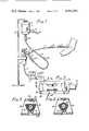
- FIG. 1is an elevational view of a blood pressure monitoring system which includes the medical flushing valve
- FIG. 2is an enlarged view of the flushing valve
- FIG. 3is a sectional view taken along line 3--3 of FIG. 2 showing the valve in its unsqueezed condition or its normal slow flow rate;
- FIG. 4is a view similar to FIG. 3, but showing the valve squeezed into its temporary fast flush condition
- FIG. 5is an enlarged view, partially in section, taken along line 5--5 of FIG. 2;
- FIG. 6is an end view taken along line 6--6 of FIG. 5;
- FIG. 7is a perspective view of a hollow connector of the valve
- FIG. 8is a sectional view taken along line 8--8 of FIG. 5;
- FIG. 9is a sectional view taken along line 9--9 of FIG. 5 showing the position of the tube during assembly.
- FIG. 10is a sectional view similar to FIG. 9, but showing the position of the tube after assembly.
- FIG. 1a system is shown for continuously monitoring blood pressure.
- This systemhas a hollow member 1, such as a needle or catheter, inserted into a patient's vein or artery.
- a connecting tube 2which can have ports or stopcocks, such as 3 and 4, for bleeding off blood samples or injecting medication into the patient.
- Tube 2connects to a rigid T-connector 5 which is shown attached to a rigid arm 6 of a transducer pressure dome 7. It is understood that the term T-connector is used in its broad sense to also include an angled Y-connector.
- the transducer dome 7includes a bleed valve 8 for use in eliminating all air from the system prior to use. It is important that no air bubbles be in the system because this can affect the hydraulic liquid pressure wave generated by the patient's heartbeat.
- the pressure dome 7 of the transducercan include a diaphragm (not shown) which can respond to liquid pressure vibrations and engage electrical strain means inside a transducer body 9 to convert hydraulic liquid pressure surges into electrical impulses.
- Such electrical impulsesare fed through a line 10 to an instrument 11 for reading the pressure fluctuations in a patient's cardiovascular system.
- Instrument 11can be an oscilloscope, an electronically activated stylus, etc. If desired, the instrument 11 can have other monitoring functions, such as at 12 and 13, to monitor pulse rate, etc. in addition to blood pressure fluctuations at each heartbeat.
- the blood pressure monitoring for each heartbeatinvolves a liquid filled line between the patient and a diaphragm in the transducer dome. Since there is no liquid flow across the diaphragm of the transducer, there is no continuous blood flow out of the patient. This is why in U.S. Pat. No. 3,581, 733 it is necessary to very slowly force a small volume of parenteral liquid, such as normal saline, into the patient to prevent blood from backing up into the catheter and connecting tube 2 where it could coagulate over an extended period of time. Coagulated blood portions in the system can materially affect the accuracy of a pressure monitoring because such coagulated blood forms a restriction in the hydraulic pressure system.
- container 15is of the collapsible bag type with a pressure cuff 17 that includes a squeeze bulb 18 and pressure gauge 19.
- the parenteral liquidflows from container 15 through a drip chamber 20 and a connecting tube 21 to a valve shown generally at 22 which is joined by flexible tube segment 23 to the rigid T-connector 5. Flow through connecting tube 21 can be controlled by conventional roller clamp 23.
- the enlarged view of the valveillustrates a protector housing that includes a base 25 connected to ends 26 and 27, which in turn are connected to a top 28 that has a narrow central section 29.
- an elastically distortable squeeze tube of rubber-like materialsuch as silicone.
- this squeeze tubeis generally transparent, or at least translucent to aid in detecting any air bubbles in the valve.
- the top wallhas a longitudinal bracing rib 32 which extends through its longitudinal length to strengthen narrow portion 29 of the top.
- Bottom wall 25has a limit lug such as cradle 33, with a concave surface, for preventing excess distortion of squeeze tube 30.
- squeeze tube 30has a generally triangular cross-sectional shape.
- valveIn FIG. 3, the valve is shown in its normal continuous slow flow rate position with the squeeze tube 30 sealingly engaging the periphery of a rigid glass flow restrictor 40 that has a bore 41 with a diameter of 0.001 to 0.004 inch. A diameter of 0.002 inch works very well and the restrictor can be made of glass tubing, such as is used for glass thermometers.
- the elastically distortable tube 30When it becomes necessary to fast flush the system of FIG. 1 with the parenteral liquid, the elastically distortable tube 30 is manually pinched through side openings of the protector housing. This causes the tube 30 to temporarily distort and create a flushing passage 42 around restrictor 40. When this is done, cradle 33 prevents undue flexure in the valve which might dislocate the restrictor. Release of the squeeze tube 30 causes it to immediately resume the FIG. 3 configuration and the predetermined slow flow rate resumed.
- FIG. 5the housing's end wall 26 is integrally formed with a stationary hollow connector 45 which is joined to flexible tube segment 23.
- End wall 27 of the protector housingis joined to a tubular retainer 46 that has a bayonet type locking channel 47.
- This bayonet type lockcan also be seen in FIG. 2.
- Fitting within tubular retainer 46is a longitudinally movable hollow connector 48 which has a bayonet type lug 49 which engages slot 47 of retainer 46.
- Movable connector 49has an internally tapered outer end and retaining ears 50 for connecting with connecting tube 21 leading from the parenteral liquid source.
- the elastically distortable tube 30When it is desired to fast flush the system of FIG. 1, the elastically distortable tube 30 is laterally squeezed between thumb and forefinger causing an upper portion of tube 30 to lift off of the periphery of glass tube 40 creating a flush passage.
- the liquidcan flow through lateral passage 55 of connector 48, and go around restrictor 40 and enter the passage of connector 45 through its lateral passage 56.
- the restrictor 40is inserted into the squeeze tube and an end of tube 30 inserted on connector 45 which is fixedly joined to the protector housing.
- the squeeze tubehas a configuration as shown in FIG. 8 at the area of assembly to connector 45.
- the right end portion of squeeze tube 30is angularly twisted as shown in FIG. 9 and a tapered end of movable connector 48 inserted into a right end of tube 30.
- Lug 49is then inserted into an entrance 60 of the bayonet type slot of the housing's retainer 46.
- retainer 46has diametrically opposed entrances 60 and 61 that are of different sizes which match with different sized lugs on diametrically opposed sides of connector 48.
- the bayonet type lockcompressively urges the connectors 45 and 48 into compressive engagement with ends of the glass restrictor 40. If glass restrictor 40 varies slightly in length from one restrictor to the next, the bayonet structure can tolerate such variances.
- the flushing valve of the present inventionworks very well when the flow restrictor is of glass, the squeeze tube is of silicone rubber, and the protective housing and hollow adapters are made of a rigid thermoplastic material.
Landscapes
- Health & Medical Sciences (AREA)
- Heart & Thoracic Surgery (AREA)
- Pulmonology (AREA)
- Engineering & Computer Science (AREA)
- Anesthesiology (AREA)
- Biomedical Technology (AREA)
- Hematology (AREA)
- Life Sciences & Earth Sciences (AREA)
- Animal Behavior & Ethology (AREA)
- General Health & Medical Sciences (AREA)
- Public Health (AREA)
- Veterinary Medicine (AREA)
- Measuring Pulse, Heart Rate, Blood Pressure Or Blood Flow (AREA)
- Infusion, Injection, And Reservoir Apparatuses (AREA)
Abstract
Description
Claims (3)
Priority Applications (2)
| Application Number | Priority Date | Filing Date | Title |
|---|---|---|---|
| US06/245,580US4381591A (en) | 1979-04-24 | 1981-03-20 | Method of assembling medical flushing valve |
| US06/437,247US4464179A (en) | 1981-03-20 | 1982-11-26 | Medical flushing valve |
Applications Claiming Priority (2)
| Application Number | Priority Date | Filing Date | Title |
|---|---|---|---|
| US06/032,832US4267835A (en) | 1979-04-24 | 1979-04-24 | Medical flushing valve |
| US06/245,580US4381591A (en) | 1979-04-24 | 1981-03-20 | Method of assembling medical flushing valve |
Related Parent Applications (1)
| Application Number | Title | Priority Date | Filing Date |
|---|---|---|---|
| US06/032,832DivisionUS4267835A (en) | 1979-04-24 | 1979-04-24 | Medical flushing valve |
Related Child Applications (1)
| Application Number | Title | Priority Date | Filing Date |
|---|---|---|---|
| US06/437,247Continuation-In-PartUS4464179A (en) | 1981-03-20 | 1982-11-26 | Medical flushing valve |
Publications (1)
| Publication Number | Publication Date |
|---|---|
| US4381591Atrue US4381591A (en) | 1983-05-03 |
Family
ID=26708943
Family Applications (1)
| Application Number | Title | Priority Date | Filing Date |
|---|---|---|---|
| US06/245,580Expired - LifetimeUS4381591A (en) | 1979-04-24 | 1981-03-20 | Method of assembling medical flushing valve |
Country Status (1)
| Country | Link |
|---|---|
| US (1) | US4381591A (en) |
Cited By (37)
| Publication number | Priority date | Publication date | Assignee | Title |
|---|---|---|---|---|
| US4444198A (en)* | 1981-12-21 | 1984-04-24 | Petre John H | Circulatory monitoring system and method |
| US4509946A (en)* | 1982-09-23 | 1985-04-09 | Mcfarlane Richard H | Flow control device |
| EP0206195A3 (en)* | 1985-06-21 | 1987-08-19 | Applied Biomedical Corporation | Gravity-independent infusion system |
| US4696305A (en)* | 1985-07-15 | 1987-09-29 | Peter von Berg Extrakorporale Systems-Medizintechnik GmbH | Flow controller |
| US4743235A (en)* | 1986-09-05 | 1988-05-10 | Medex, Inc. | Flush control device |
| DE4207917A1 (en)* | 1991-03-18 | 1992-09-24 | Lucas Victor Grifols | FLOW CONTROLLER FOR CATHETER AND SIMILAR DEVICES AND METHOD FOR THE PRODUCTION THEREOF |
| US5169393A (en)* | 1990-09-04 | 1992-12-08 | Robert Moorehead | Two-way outdwelling slit valving of medical liquid flow through a cannula and methods |
| US5201722A (en)* | 1990-09-04 | 1993-04-13 | Moorehead Robert H | Two-way outdwelling slit valving of medical liquid flow through a cannula and methods |
| US5205834A (en)* | 1990-09-04 | 1993-04-27 | Moorehead H Robert | Two-way outdwelling slit valving of medical liquid flow through a cannula and methods |
| WO1993010831A1 (en)* | 1991-12-06 | 1993-06-10 | Block Medical, Inc. | Patient controlled bolus dosage infuser |
| US5322506A (en)* | 1989-07-31 | 1994-06-21 | C. R. Bard, Inc. | Irrigation system with high flow bypass for use with endoscopic procedure |
| US5549866A (en)* | 1991-03-18 | 1996-08-27 | Victor Grifols Lucas | Process of making a flow regulation device |
| WO1998005378A1 (en)* | 1996-08-05 | 1998-02-12 | Alaris Medical Systems, Inc. | Valve apparatus for use with an iv set |
| US20020007156A1 (en)* | 2000-05-11 | 2002-01-17 | Miles Scott D. | Apparatus and method for preventing free flow in an infusion line |
| US6659976B2 (en)* | 2001-04-16 | 2003-12-09 | Zevek, Inc. | Feeding set adaptor |
| US6802823B2 (en) | 2001-08-22 | 2004-10-12 | Breg, Inc. | Medication delivery system having selective automated or manual discharge |
| US20040220542A1 (en)* | 2000-05-11 | 2004-11-04 | David Cise | Apparatus and method for preventing free flow in an infusion line |
| USD503799S1 (en) | 2002-09-09 | 2005-04-05 | Zevex, Inc. | In-line occluder |
| USD503978S1 (en) | 2002-09-09 | 2005-04-12 | Zevex, Inc. | In-line occluder |
| USD504506S1 (en) | 2002-06-28 | 2005-04-26 | Zevex, Inc. | Feeding pump cartridge |
| USD536783S1 (en) | 2002-06-28 | 2007-02-13 | Zevex, Inc. | Enteral feeding pump cassette connector |
| US20090001718A1 (en)* | 2006-03-02 | 2009-01-01 | Gambro Lundia Ab | Hydraulic Connector and a Hydraulic Circuit Incorporating the Connector |
| US20090254034A1 (en)* | 2008-04-01 | 2009-10-08 | Kent Beck | Safety occluder and method of use |
| US20100082001A1 (en)* | 2008-04-01 | 2010-04-01 | Kent Beck | Anti-free flow mechanism for enteral feeding pumps |
| US20100204651A1 (en)* | 2009-02-06 | 2010-08-12 | Mark Stringham | Automatic safety occluder |
| US7815612B2 (en) | 2000-05-11 | 2010-10-19 | Zevex, Inc. | Apparatus and method for preventing free flow in an infusion line |
| USD672455S1 (en) | 2010-10-01 | 2012-12-11 | Zevex, Inc. | Fluid delivery cassette |
| US8425470B2 (en) | 2008-04-01 | 2013-04-23 | Zevex, Inc. | Anti-free-flow mechanism for enteral feeding pumps |
| WO2013102236A1 (en)* | 2012-01-04 | 2013-07-11 | Surgical Apps Pty Ltd | A manually operated medical pump |
| US20140071762A1 (en)* | 2012-09-12 | 2014-03-13 | Kabushiki Kaisha Toshiba | Nonvolatile semiconductor memory device and method of manufacturing the same |
| US8801656B2 (en) | 2012-10-29 | 2014-08-12 | Hospira, Inc. | Fluid flow passage to improve air-in-line detection |
| US8911414B2 (en) | 2010-10-01 | 2014-12-16 | Zevex, Inc. | Anti free-flow occluder and priming actuator pad |
| US10143795B2 (en) | 2014-08-18 | 2018-12-04 | Icu Medical, Inc. | Intravenous pole integrated power, control, and communication system and method for an infusion pump |
| US10918787B2 (en) | 2015-05-26 | 2021-02-16 | Icu Medical, Inc. | Disposable infusion fluid delivery device for programmable large volume drug delivery |
| USD939079S1 (en) | 2019-08-22 | 2021-12-21 | Icu Medical, Inc. | Infusion pump |
| US11213619B2 (en) | 2013-11-11 | 2022-01-04 | Icu Medical, Inc. | Thermal management system and method for medical devices |
| USD1052728S1 (en) | 2021-11-12 | 2024-11-26 | Icu Medical, Inc. | Medical fluid infusion pump |
Citations (22)
| Publication number | Priority date | Publication date | Assignee | Title |
|---|---|---|---|---|
| US317157A (en)* | 1885-05-05 | lowrie | ||
| FR451071A (en)* | 1912-11-27 | 1913-04-10 | Rene Tampier | Fitting for metal pipes |
| GB182656A (en) | 1921-06-07 | 1922-07-13 | Charles Orme Bastian | A new or improved bye-pass tap or valve for gas or liquids |
| US2706101A (en)* | 1951-04-07 | 1955-04-12 | Jacob J Cantor | Valve |
| US2832344A (en)* | 1954-12-27 | 1958-04-29 | Davidson Emil | Blood sample collector |
| US2946555A (en)* | 1957-09-16 | 1960-07-26 | Jacob J Cantor | Valve |
| US3111125A (en)* | 1961-11-06 | 1963-11-19 | Rudolf R Schulte | Drainage device |
| US3376625A (en)* | 1965-07-19 | 1968-04-09 | Mac Bee Engineering Inc | Method of making fluid pulsation dampeners |
| US3399676A (en)* | 1965-02-12 | 1968-09-03 | Jack E. Mclaughlin | Liquid dispensing apparatus for use in body treatment |
| US3581733A (en)* | 1967-12-30 | 1971-06-01 | Philips Corp | Heart catheterization device |
| US3626959A (en)* | 1970-02-04 | 1971-12-14 | Deseret Pharma | Intravenous flow control |
| US3675891A (en)* | 1970-09-18 | 1972-07-11 | Voys Inc Le | Continuous catheter flushing apparatus |
| US3704704A (en)* | 1970-10-12 | 1972-12-05 | Ramon L Gonzales | Birth control valve |
| US3882026A (en)* | 1972-08-14 | 1975-05-06 | American Hospital Supply Corp | Hydrophobic filter device for medical liquids |
| US3890687A (en)* | 1974-11-04 | 1975-06-24 | Joseph H Goldberg | Method for spring assembly |
| US3985140A (en)* | 1975-06-30 | 1976-10-12 | Cordis Corporation | Dual pressure valve for use in ventricular shunt system |
| US3999542A (en)* | 1975-04-10 | 1976-12-28 | Shaw Robert F | Anti-clogging liquid administration apparatus and method |
| US4065093A (en)* | 1976-05-24 | 1977-12-27 | Baxter Travenol Laboratories, Inc. | Flow control device |
| US4106675A (en)* | 1976-12-22 | 1978-08-15 | The Kendall Company | Liquid sampling device |
| US4109837A (en)* | 1976-12-22 | 1978-08-29 | The Kendall Company | Liquid sampling device |
| US4146082A (en)* | 1977-07-27 | 1979-03-27 | Cabot Corporation | Vacuum chucks |
| US4192303A (en)* | 1978-06-29 | 1980-03-11 | Walker Ralph S | Flow regulating device for arterial catheter systems |
- 1981
- 1981-03-20USUS06/245,580patent/US4381591A/ennot_activeExpired - Lifetime
Patent Citations (22)
| Publication number | Priority date | Publication date | Assignee | Title |
|---|---|---|---|---|
| US317157A (en)* | 1885-05-05 | lowrie | ||
| FR451071A (en)* | 1912-11-27 | 1913-04-10 | Rene Tampier | Fitting for metal pipes |
| GB182656A (en) | 1921-06-07 | 1922-07-13 | Charles Orme Bastian | A new or improved bye-pass tap or valve for gas or liquids |
| US2706101A (en)* | 1951-04-07 | 1955-04-12 | Jacob J Cantor | Valve |
| US2832344A (en)* | 1954-12-27 | 1958-04-29 | Davidson Emil | Blood sample collector |
| US2946555A (en)* | 1957-09-16 | 1960-07-26 | Jacob J Cantor | Valve |
| US3111125A (en)* | 1961-11-06 | 1963-11-19 | Rudolf R Schulte | Drainage device |
| US3399676A (en)* | 1965-02-12 | 1968-09-03 | Jack E. Mclaughlin | Liquid dispensing apparatus for use in body treatment |
| US3376625A (en)* | 1965-07-19 | 1968-04-09 | Mac Bee Engineering Inc | Method of making fluid pulsation dampeners |
| US3581733A (en)* | 1967-12-30 | 1971-06-01 | Philips Corp | Heart catheterization device |
| US3626959A (en)* | 1970-02-04 | 1971-12-14 | Deseret Pharma | Intravenous flow control |
| US3675891A (en)* | 1970-09-18 | 1972-07-11 | Voys Inc Le | Continuous catheter flushing apparatus |
| US3704704A (en)* | 1970-10-12 | 1972-12-05 | Ramon L Gonzales | Birth control valve |
| US3882026A (en)* | 1972-08-14 | 1975-05-06 | American Hospital Supply Corp | Hydrophobic filter device for medical liquids |
| US3890687A (en)* | 1974-11-04 | 1975-06-24 | Joseph H Goldberg | Method for spring assembly |
| US3999542A (en)* | 1975-04-10 | 1976-12-28 | Shaw Robert F | Anti-clogging liquid administration apparatus and method |
| US3985140A (en)* | 1975-06-30 | 1976-10-12 | Cordis Corporation | Dual pressure valve for use in ventricular shunt system |
| US4065093A (en)* | 1976-05-24 | 1977-12-27 | Baxter Travenol Laboratories, Inc. | Flow control device |
| US4106675A (en)* | 1976-12-22 | 1978-08-15 | The Kendall Company | Liquid sampling device |
| US4109837A (en)* | 1976-12-22 | 1978-08-29 | The Kendall Company | Liquid sampling device |
| US4146082A (en)* | 1977-07-27 | 1979-03-27 | Cabot Corporation | Vacuum chucks |
| US4192303A (en)* | 1978-06-29 | 1980-03-11 | Walker Ralph S | Flow regulating device for arterial catheter systems |
Non-Patent Citations (1)
| Title |
|---|
| "Delta Flow", The Deseret Company, Catalogue No. 1280, Jun. 1978.* |
Cited By (65)
| Publication number | Priority date | Publication date | Assignee | Title |
|---|---|---|---|---|
| US4444198A (en)* | 1981-12-21 | 1984-04-24 | Petre John H | Circulatory monitoring system and method |
| US4509946A (en)* | 1982-09-23 | 1985-04-09 | Mcfarlane Richard H | Flow control device |
| EP0206195A3 (en)* | 1985-06-21 | 1987-08-19 | Applied Biomedical Corporation | Gravity-independent infusion system |
| US4696305A (en)* | 1985-07-15 | 1987-09-29 | Peter von Berg Extrakorporale Systems-Medizintechnik GmbH | Flow controller |
| US4743235A (en)* | 1986-09-05 | 1988-05-10 | Medex, Inc. | Flush control device |
| US5322506A (en)* | 1989-07-31 | 1994-06-21 | C. R. Bard, Inc. | Irrigation system with high flow bypass for use with endoscopic procedure |
| US5169393A (en)* | 1990-09-04 | 1992-12-08 | Robert Moorehead | Two-way outdwelling slit valving of medical liquid flow through a cannula and methods |
| US5201722A (en)* | 1990-09-04 | 1993-04-13 | Moorehead Robert H | Two-way outdwelling slit valving of medical liquid flow through a cannula and methods |
| US5205834A (en)* | 1990-09-04 | 1993-04-27 | Moorehead H Robert | Two-way outdwelling slit valving of medical liquid flow through a cannula and methods |
| DE4207917A1 (en)* | 1991-03-18 | 1992-09-24 | Lucas Victor Grifols | FLOW CONTROLLER FOR CATHETER AND SIMILAR DEVICES AND METHOD FOR THE PRODUCTION THEREOF |
| AT401144B (en)* | 1991-03-18 | 1996-06-25 | Lucas Victor Grifols | FLOW CONTROLLER FOR CATHETER AND SIMILAR DEVICES AND METHOD FOR THE PRODUCTION THEREOF |
| US5549866A (en)* | 1991-03-18 | 1996-08-27 | Victor Grifols Lucas | Process of making a flow regulation device |
| WO1993010831A1 (en)* | 1991-12-06 | 1993-06-10 | Block Medical, Inc. | Patient controlled bolus dosage infuser |
| US5826621A (en)* | 1996-08-05 | 1998-10-27 | Alaris Medical Systems, Inc. | Valve apparatus |
| WO1998005378A1 (en)* | 1996-08-05 | 1998-02-12 | Alaris Medical Systems, Inc. | Valve apparatus for use with an iv set |
| US7150727B2 (en) | 2000-05-11 | 2006-12-19 | Zevex, Inc. | Apparatus and method for preventing free flow in an infusion line |
| US6623447B2 (en) | 2000-05-11 | 2003-09-23 | Zevex, Inc. | Apparatus and method for preventing free flow in an infusion line |
| US7976513B2 (en) | 2000-05-11 | 2011-07-12 | Zevex, Inc. | Apparatus and method for selectively controlling flow in an infusion line |
| US20040220542A1 (en)* | 2000-05-11 | 2004-11-04 | David Cise | Apparatus and method for preventing free flow in an infusion line |
| US7815612B2 (en) | 2000-05-11 | 2010-10-19 | Zevex, Inc. | Apparatus and method for preventing free flow in an infusion line |
| US7367963B2 (en) | 2000-05-11 | 2008-05-06 | Zevex, Inc. | Apparatus and method for preventing free flow in an infusion line |
| US20020007156A1 (en)* | 2000-05-11 | 2002-01-17 | Miles Scott D. | Apparatus and method for preventing free flow in an infusion line |
| US20050119625A1 (en)* | 2000-05-11 | 2005-06-02 | Scott Miles | Apparatus and method for preventing free flow in an infusion line |
| US20050283121A1 (en)* | 2000-05-11 | 2005-12-22 | David Cise | Apparatus and method for preventing free flow in an infusion line |
| US6979311B2 (en) | 2000-05-11 | 2005-12-27 | Zevex, Inc. | Apparatus and method for preventing free flow in an infusion line |
| US6659976B2 (en)* | 2001-04-16 | 2003-12-09 | Zevek, Inc. | Feeding set adaptor |
| US7070575B2 (en) | 2001-04-16 | 2006-07-04 | Zevex, Inc. | Adaptor for feeding sets |
| US20050209552A1 (en)* | 2001-04-16 | 2005-09-22 | Beck Kent F | Adaptor for feeding sets |
| US7309333B2 (en) | 2001-08-22 | 2007-12-18 | Breg, Inc. | Medication delivery system having selective automated or manual discharge |
| US6802823B2 (en) | 2001-08-22 | 2004-10-12 | Breg, Inc. | Medication delivery system having selective automated or manual discharge |
| USD536783S1 (en) | 2002-06-28 | 2007-02-13 | Zevex, Inc. | Enteral feeding pump cassette connector |
| USD504506S1 (en) | 2002-06-28 | 2005-04-26 | Zevex, Inc. | Feeding pump cartridge |
| USD505199S1 (en) | 2002-06-28 | 2005-05-17 | Zevex, Inc. | Feeding pump cartridge |
| USD634005S1 (en) | 2002-09-09 | 2011-03-08 | Zevex, Inc. | In-line occluder |
| USD503978S1 (en) | 2002-09-09 | 2005-04-12 | Zevex, Inc. | In-line occluder |
| USD635664S1 (en) | 2002-09-09 | 2011-04-05 | Zevex, Inc. | In-line occluder |
| USD503799S1 (en) | 2002-09-09 | 2005-04-05 | Zevex, Inc. | In-line occluder |
| US20090001718A1 (en)* | 2006-03-02 | 2009-01-01 | Gambro Lundia Ab | Hydraulic Connector and a Hydraulic Circuit Incorporating the Connector |
| US7914049B2 (en)* | 2006-03-02 | 2011-03-29 | Gambro Lundia Ab | Hydraulic connector and a hydraulic circuit incorporating the connector |
| US20090254034A1 (en)* | 2008-04-01 | 2009-10-08 | Kent Beck | Safety occluder and method of use |
| US20110028899A1 (en)* | 2008-04-01 | 2011-02-03 | Kent Beck | Anti-free flow mechanism for enteral feeding pumps |
| US20100082001A1 (en)* | 2008-04-01 | 2010-04-01 | Kent Beck | Anti-free flow mechanism for enteral feeding pumps |
| US8343111B2 (en) | 2008-04-01 | 2013-01-01 | Zevex, Inc. | Anti-free flow mechanism for enteral feeding pumps |
| US8425470B2 (en) | 2008-04-01 | 2013-04-23 | Zevex, Inc. | Anti-free-flow mechanism for enteral feeding pumps |
| US8876787B2 (en) | 2008-04-01 | 2014-11-04 | Zevex, Inc. | Anti-free-flow mechanism for enteral feeding pumps |
| US9017296B2 (en) | 2008-04-01 | 2015-04-28 | Zevex, Inc. | Safety occluder and method of use |
| US20100204651A1 (en)* | 2009-02-06 | 2010-08-12 | Mark Stringham | Automatic safety occluder |
| US7998121B2 (en) | 2009-02-06 | 2011-08-16 | Zevex, Inc. | Automatic safety occluder |
| US8491543B2 (en) | 2009-02-06 | 2013-07-23 | Zevex, Inc. | Automatic safety occluder |
| USD672455S1 (en) | 2010-10-01 | 2012-12-11 | Zevex, Inc. | Fluid delivery cassette |
| US8911414B2 (en) | 2010-10-01 | 2014-12-16 | Zevex, Inc. | Anti free-flow occluder and priming actuator pad |
| WO2013102236A1 (en)* | 2012-01-04 | 2013-07-11 | Surgical Apps Pty Ltd | A manually operated medical pump |
| US20140350475A1 (en)* | 2012-01-04 | 2014-11-27 | Surgical Apps Pty Ltd | Manually operated medical pump |
| US20140071762A1 (en)* | 2012-09-12 | 2014-03-13 | Kabushiki Kaisha Toshiba | Nonvolatile semiconductor memory device and method of manufacturing the same |
| US9117525B2 (en)* | 2012-09-12 | 2015-08-25 | Kabushiki Kaisha Toshiba | Nonvolatile semiconductor memory device and method of manufacturing the same |
| US8801656B2 (en) | 2012-10-29 | 2014-08-12 | Hospira, Inc. | Fluid flow passage to improve air-in-line detection |
| US12076525B2 (en) | 2013-11-11 | 2024-09-03 | Icu Medical, Inc. | Thermal management system and method for medical devices |
| US11213619B2 (en) | 2013-11-11 | 2022-01-04 | Icu Medical, Inc. | Thermal management system and method for medical devices |
| US10143795B2 (en) | 2014-08-18 | 2018-12-04 | Icu Medical, Inc. | Intravenous pole integrated power, control, and communication system and method for an infusion pump |
| US10918787B2 (en) | 2015-05-26 | 2021-02-16 | Icu Medical, Inc. | Disposable infusion fluid delivery device for programmable large volume drug delivery |
| US11660386B2 (en) | 2015-05-26 | 2023-05-30 | Icu Medical, Inc. | Disposable infusion fluid delivery device for programmable large volume drug delivery |
| US12156986B2 (en) | 2015-05-26 | 2024-12-03 | Icu Medical, Inc. | Disposable infusion fluid delivery device for programmable large volume drug delivery |
| USD939079S1 (en) | 2019-08-22 | 2021-12-21 | Icu Medical, Inc. | Infusion pump |
| USD1076062S1 (en) | 2019-08-22 | 2025-05-20 | Icu Medical, Inc. | Infusion pump |
| USD1052728S1 (en) | 2021-11-12 | 2024-11-26 | Icu Medical, Inc. | Medical fluid infusion pump |
Similar Documents
| Publication | Publication Date | Title |
|---|---|---|
| US4381591A (en) | Method of assembling medical flushing valve | |
| US4267835A (en) | Medical flushing valve | |
| US4645496A (en) | Continuous catheter flushing flow control device | |
| US4192303A (en) | Flow regulating device for arterial catheter systems | |
| US4073297A (en) | Catheter | |
| US4245636A (en) | Continuous flushing apparatus | |
| US4160448A (en) | Blood pressure measuring catheter | |
| US4149535A (en) | Catheter holding device | |
| US5330435A (en) | Valve for a catheter assembly | |
| US4307731A (en) | Multiple sampling needle having one-way valve | |
| EP0000041B1 (en) | An intravascular catheter | |
| US5147336A (en) | Adapter kit for a catheter introducer | |
| US4509946A (en) | Flow control device | |
| AU675749B2 (en) | A catheter or cannula system | |
| US5314410A (en) | Entry indicator device for arterial or intravenous needle | |
| US4457487A (en) | Flushing device | |
| US4337770A (en) | Flow regulating device for arterial catheter systems | |
| JPS6249863A (en) | Injection apparatus | |
| EP0006761A1 (en) | Flow regulating device | |
| US5607390A (en) | Dialysis probe | |
| US20230364381A1 (en) | Vascular Access Device Assembly Facilitating Single-Handed Patency Probe Advancement | |
| US4267834A (en) | System for flushing a medical fluid | |
| JPH067864B2 (en) | Products with hemostatic valve gaskets and elastic valve gaskets | |
| US4464179A (en) | Medical flushing valve | |
| US4834108A (en) | Blocking filter to prevent air flow into a fluid conduit to a transducer |
Legal Events
| Date | Code | Title | Description |
|---|---|---|---|
| STCF | Information on status: patent grant | Free format text:PATENTED CASE | |
| MAFP | Maintenance fee payment | Free format text:PAYMENT OF MAINTENANCE FEE, 4TH YEAR, PL 96-517 (ORIGINAL EVENT CODE: M170); ENTITY STATUS OF PATENT OWNER: LARGE ENTITY Year of fee payment:4 | |
| AS | Assignment | Owner name:BAXTER TRAVENOL LABORATORIES, INC. A CORP. OF DE Free format text:MERGER;ASSIGNOR:AMERICAN HOSPITAL SUPPLY CORPORATION INTO;REEL/FRAME:004760/0345 Effective date:19870126 | |
| FEPP | Fee payment procedure | Free format text:PAYOR NUMBER ASSIGNED (ORIGINAL EVENT CODE: ASPN); ENTITY STATUS OF PATENT OWNER: LARGE ENTITY | |
| AS | Assignment | Owner name:BAXTER INTERNATIONAL INC. Free format text:CHANGE OF NAME;ASSIGNOR:BAXTER TRAVENOL LABORATORIES, INC., A CORP. OF DE;REEL/FRAME:005050/0870 Effective date:19880518 | |
| MAFP | Maintenance fee payment | Free format text:PAYMENT OF MAINTENANCE FEE, 8TH YEAR, PL 96-517 (ORIGINAL EVENT CODE: M171); ENTITY STATUS OF PATENT OWNER: LARGE ENTITY Year of fee payment:8 | |
| MAFP | Maintenance fee payment | Free format text:PAYMENT OF MAINTENANCE FEE, 12TH YEAR, LARGE ENTITY (ORIGINAL EVENT CODE: M185); ENTITY STATUS OF PATENT OWNER: LARGE ENTITY Year of fee payment:12 | |
| AS | Assignment | Owner name:EDWARDS LIFESCIENCES CORPORATION, CALIFORNIA Free format text:ASSIGNMENT OF ASSIGNORS INTEREST;ASSIGNOR:BAXTER INTERNATIONAL INC.;REEL/FRAME:010901/0274 Effective date:20000609 |