US4381129A - Grounded, multi-pin connector for shielded flat cable - Google Patents
Grounded, multi-pin connector for shielded flat cableDownload PDFInfo
- Publication number
- US4381129A US4381129AUS06/282,634US28263481AUS4381129AUS 4381129 AUS4381129 AUS 4381129AUS 28263481 AUS28263481 AUS 28263481AUS 4381129 AUS4381129 AUS 4381129A
- Authority
- US
- United States
- Prior art keywords
- housing
- section
- conductive
- cable
- conductive means
- Prior art date
- Legal status (The legal status is an assumption and is not a legal conclusion. Google has not performed a legal analysis and makes no representation as to the accuracy of the status listed.)
- Expired - Lifetime
Links
- 239000004020conductorSubstances0.000claimsdescription31
- 230000005855radiationEffects0.000claimsdescription17
- 230000008878couplingEffects0.000claimsdescription16
- 238000010168coupling processMethods0.000claimsdescription16
- 238000005859coupling reactionMethods0.000claimsdescription16
- RYGMFSIKBFXOCR-UHFFFAOYSA-NCopperChemical compound[Cu]RYGMFSIKBFXOCR-UHFFFAOYSA-N0.000claimsdescription2
- 230000009471actionEffects0.000claimsdescription2
- 229910052802copperInorganic materials0.000claimsdescription2
- 239000010949copperSubstances0.000claimsdescription2
- 230000013011matingEffects0.000claims4
- 238000005452bendingMethods0.000description6
- 230000000694effectsEffects0.000description4
- 238000003780insertionMethods0.000description4
- 230000037431insertionEffects0.000description4
- 230000007935neutral effectEffects0.000description4
- 239000000463materialSubstances0.000description3
- 239000002184metalSubstances0.000description3
- 229910052751metalInorganic materials0.000description3
- 230000010365information processingEffects0.000description2
- 238000009413insulationMethods0.000description2
- 230000002452interceptive effectEffects0.000description2
- 239000007769metal materialSubstances0.000description2
- 238000000034methodMethods0.000description2
- 238000012986modificationMethods0.000description2
- 230000004048modificationEffects0.000description2
- 238000007493shaping processMethods0.000description2
- 241000283973Oryctolagus cuniculusSpecies0.000description1
- 230000005540biological transmissionEffects0.000description1
- 230000015572biosynthetic processEffects0.000description1
- 230000000593degrading effectEffects0.000description1
- 238000010894electron beam technologyMethods0.000description1
- 238000009434installationMethods0.000description1
- 230000000737periodic effectEffects0.000description1
- 229920001084poly(chloroprene)Polymers0.000description1
- 230000008569processEffects0.000description1
- 238000009877renderingMethods0.000description1
- 238000001228spectrumMethods0.000description1
Images
Classifications
- H—ELECTRICITY
- H01—ELECTRIC ELEMENTS
- H01R—ELECTRICALLY-CONDUCTIVE CONNECTIONS; STRUCTURAL ASSOCIATIONS OF A PLURALITY OF MUTUALLY-INSULATED ELECTRICAL CONNECTING ELEMENTS; COUPLING DEVICES; CURRENT COLLECTORS
- H01R12/00—Structural associations of a plurality of mutually-insulated electrical connecting elements, specially adapted for printed circuits, e.g. printed circuit boards [PCB], flat or ribbon cables, or like generally planar structures, e.g. terminal strips, terminal blocks; Coupling devices specially adapted for printed circuits, flat or ribbon cables, or like generally planar structures; Terminals specially adapted for contact with, or insertion into, printed circuits, flat or ribbon cables, or like generally planar structures
- H01R12/50—Fixed connections
- H01R12/59—Fixed connections for flexible printed circuits, flat or ribbon cables or like structures
- H01R12/594—Fixed connections for flexible printed circuits, flat or ribbon cables or like structures for shielded flat cable
- H—ELECTRICITY
- H01—ELECTRIC ELEMENTS
- H01R—ELECTRICALLY-CONDUCTIVE CONNECTIONS; STRUCTURAL ASSOCIATIONS OF A PLURALITY OF MUTUALLY-INSULATED ELECTRICAL CONNECTING ELEMENTS; COUPLING DEVICES; CURRENT COLLECTORS
- H01R12/00—Structural associations of a plurality of mutually-insulated electrical connecting elements, specially adapted for printed circuits, e.g. printed circuit boards [PCB], flat or ribbon cables, or like generally planar structures, e.g. terminal strips, terminal blocks; Coupling devices specially adapted for printed circuits, flat or ribbon cables, or like generally planar structures; Terminals specially adapted for contact with, or insertion into, printed circuits, flat or ribbon cables, or like generally planar structures
- H01R12/70—Coupling devices
- H01R12/77—Coupling devices for flexible printed circuits, flat or ribbon cables or like structures
- H01R12/771—Details
- H01R12/775—Ground or shield arrangements
- H—ELECTRICITY
- H01—ELECTRIC ELEMENTS
- H01R—ELECTRICALLY-CONDUCTIVE CONNECTIONS; STRUCTURAL ASSOCIATIONS OF A PLURALITY OF MUTUALLY-INSULATED ELECTRICAL CONNECTING ELEMENTS; COUPLING DEVICES; CURRENT COLLECTORS
- H01R13/00—Details of coupling devices of the kinds covered by groups H01R12/70 or H01R24/00 - H01R33/00
- H01R13/648—Protective earth or shield arrangements on coupling devices, e.g. anti-static shielding
- H01R13/658—High frequency shielding arrangements, e.g. against EMI [Electro-Magnetic Interference] or EMP [Electro-Magnetic Pulse]
- H01R13/6581—Shield structure
- H01R13/6582—Shield structure with resilient means for engaging mating connector
- H—ELECTRICITY
- H01—ELECTRIC ELEMENTS
- H01R—ELECTRICALLY-CONDUCTIVE CONNECTIONS; STRUCTURAL ASSOCIATIONS OF A PLURALITY OF MUTUALLY-INSULATED ELECTRICAL CONNECTING ELEMENTS; COUPLING DEVICES; CURRENT COLLECTORS
- H01R12/00—Structural associations of a plurality of mutually-insulated electrical connecting elements, specially adapted for printed circuits, e.g. printed circuit boards [PCB], flat or ribbon cables, or like generally planar structures, e.g. terminal strips, terminal blocks; Coupling devices specially adapted for printed circuits, flat or ribbon cables, or like generally planar structures; Terminals specially adapted for contact with, or insertion into, printed circuits, flat or ribbon cables, or like generally planar structures
- H01R12/70—Coupling devices
- H01R12/77—Coupling devices for flexible printed circuits, flat or ribbon cables or like structures
- H—ELECTRICITY
- H01—ELECTRIC ELEMENTS
- H01R—ELECTRICALLY-CONDUCTIVE CONNECTIONS; STRUCTURAL ASSOCIATIONS OF A PLURALITY OF MUTUALLY-INSULATED ELECTRICAL CONNECTING ELEMENTS; COUPLING DEVICES; CURRENT COLLECTORS
- H01R13/00—Details of coupling devices of the kinds covered by groups H01R12/70 or H01R24/00 - H01R33/00
- H01R13/73—Means for mounting coupling parts to apparatus or structures, e.g. to a wall
- H01R13/74—Means for mounting coupling parts in openings of a panel
- Y—GENERAL TAGGING OF NEW TECHNOLOGICAL DEVELOPMENTS; GENERAL TAGGING OF CROSS-SECTIONAL TECHNOLOGIES SPANNING OVER SEVERAL SECTIONS OF THE IPC; TECHNICAL SUBJECTS COVERED BY FORMER USPC CROSS-REFERENCE ART COLLECTIONS [XRACs] AND DIGESTS
- Y10—TECHNICAL SUBJECTS COVERED BY FORMER USPC
- Y10S—TECHNICAL SUBJECTS COVERED BY FORMER USPC CROSS-REFERENCE ART COLLECTIONS [XRACs] AND DIGESTS
- Y10S439/00—Electrical connectors
- Y10S439/939—Electrical connectors with grounding to metal mounting panel
Definitions
- This inventiongenerally relates to multi-pin, flat cable connectors and more specifically is directed to an improved multi-pin connector for grounding a flat, shielded conductor.
- Radio frequency (RF) energyis, in general, an alternating-current energy at any frequency in the radio spectrum between approximately 10 KHZ and 3 ⁇ 10 8 MHZ.
- the higher frequenciesare used increasingly primarily because of the availability of smaller components and the requirement for increased signal information rates. This is particularly true in information processing systems where large amounts of information are carried by high frequency signals which are then processed by densely packed, sub-miniature logic circuitry. These high frequency signals tend to escape from their medium of transmission and interfere with surrounding electronic components and conductors. This phenomenon is termed RF interference, the effects of which may vary from rendering electronic equipment totally unusable to periodic performance inaccuracies in high speed signal processing equipment.
- RF interferenceis particularly troublesome in an information processing system such as a word processor.
- pulsed signals at 5-10 MHZare used to drive various sub-systems including several levels of logic circuitry and video display electron beam drive circuitry. These high frequency pulsed signals have extremely rapid rise rates and generate harmonics which interfere particularly with the VHF reception band of nearby television receivers at 54-60 MHZ.
- the picture carrier signal in a conventional television receiveroperates at 55.25 MHZ which is also subject to RF interference as evidenced by the commonly observed "herringbone" effect on the television receiver's video display.
- the degrading effects of RF interference on a television receivercan be partially alleviated through the use of coaxial and twin lead antenna conductors. But this only reduces the effects of RF interference without completely eliminating them since the antenna itself is still susceptible to receiving interfering signal inputs.
- a television receiver employing a rabbit ears-type of antenna installationremains highly susceptible to RF interference.
- Still another object of the present inventionis to provide an improved grounded connector to which many existing multi-pin, flat cable connectors may be easily adapted.
- a still further object of the present inventionis to provide a connector with improved grounding characteristics for grounding the conductive shield of a multi-conductor flat cable.
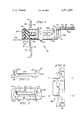
- FIG. 1is a partially cutaway cross sectional view of the panel-mounted receptacle and plug portions of a grounded, multi-pin connector in accordance with the present invention
- FIG. 2is a front view of the grounded element of the multi-pin connector in accordance with a preferred embodiment of the present invention
- FIG. 3is a front view of the receptacle portion of the multi-pin connector positioned in the aperture of a panel wherein is also positioned a grounded element in accordance with the present invention.
- FIG. 4shows the planar configuration of the ground coupler element prior to its re-shaping for insertion in and mounting on the plug portion of the grounded, multi-pin connector wherein the axes along which the ground coupler element is folded are indicated.
- FIG. 1there is shown a grounded, multi-pin connector 10 for a shielded flat cable in accordance with the present invention.
- Grounded element 22is mounted in combination with receptacle 12 to panel 16 so as to be in electrical contact with the grounded surface 20 of the panel 16.
- Receptacle 12 and grounded element 22project through aperture 17 in panel 16.
- Plug portion 14is coupled to receptacle portion 12 in assembling multi-pin connector 10.
- Plug portion 14is provided with ground coupler element 40, the contact element 42 of which is in electrical contact with conductive shield 52 of plug-mounted conductor 50.
- Receptacle portion 12 of the multi-pin connector 10is mounted in a conventional manner to panel 16.
- Receptacle 12is comprised of a first section 12a and a second section 12b which are connected along groove 30 which defines their area of joinder.
- Conductor 32is positioned between first and second receptacle sections 12a and 12b during the assembly process with metal contacts (not shown) located therein for piercing the insulation of conductor 32 in establishing electrical contact between conducting pins 36 of receptacle 12 and conductor 32.
- Receptacle 12includes a cavity 34 formed in its forward section in which are positioned conducting pins 36 in a fixed planar array.
- Receptacle 12is mounted in a conventional manner to panel 16 so as to project through an aperture 17 located therein.
- Panel 16typically forms one enclosing surface of an electronic device and includes an outer surface 18 which is generally painted and an inner surface 20 which is unpainted.
- inner surface 20is maintained at neutral ground potential.
- grounded element 22Mounted to panel 16 in combination with receptacle 12 is grounded element 22.
- grounded element 22having a base 24 and lateral sections 24a and 24b which, in combination, define a channel in grounded element 22 in which receptacle 12 is positioned when inserted in aperture 17.
- Grounded element base 24is positioned beneath receptacle 12 while lateral sections 24a and 24b are located on each side of receptacle 12 when mounted in aperture 17.
- connector receptacle 12The mounting of connector receptacle 12 in the aperture 17 of panel 16 is shown in FIG. 3.
- Securing means 60 and 62which are shown in FIG. 3 as threaded screws or small bolts, are positioned, from front to back, through panel 18, grounded element 22 (shown in dotted outline form), and connector receptacle 12.
- Connector receptacle 12includes a hollowed-out, or cavity, portion 34 or its front surface in which are located a plurality of rigid conducting pins arranged in a fixed planar array.
- Conducting pins 36extend through connector receptacle 12 to approximately where sections 12a and 12b of receptacle 12 meet along the plane defined by line 30. Thus, when sections 12a and 12b are properly assembled, electrical contact is established between pins 36 and the conductors of the receptacle-mounted flat cable 32.
- projecting shelf 26which projects from grounded element base 24 through aperture 17 when grounded element 22 is properly mounted on panel 16.
- the spacing of connector receptacle 12 and projecting shelf 26 of grounded element 22is such that when connector receptacle 12 is positioned in aperture 17 one of its lateral surfaces is in close proximity to the flat portion of projecting shelf 26.
- projecting shelf 26is in contact with the lower lateral surface of connector receptacle 12 such that another conducting element may be positioned therebetween by virtue of the flexible character of grounded element 22, as will be presently explained.
- the flexibility of grounded element 22, and in particular the projecting shelf 26 thereof,is shown in FIG.
- Projecting shelf 26may be displaced away from the lateral surface of receptacle 12 which it is positioned adjacent to, or in contact with.
- Projecting shelf 26includes a forward edge 28 which is directed away from connector receptacle 12 when both are properly positioned in aperture 17 of panel 16. This forward edge 28 of projecting shelf 26 facilitates the insertion of a thin object between projecting shelf 26 and the adjacent lateral surface of connector receptacle 12.
- the second primary part of grounded, multi-pin connector 10is plug portion 14. Included in the forward surface of plug 14 are a plurality of conductive recesses 38 which, similar to the conducting pins 36 of receptacle 12, are positioned in a fixed planar array therein. Conducting elements are included in conductive recesses 38 and extend, although not shown in FIG. 1 since this is not a part of the present invention, to the plane defined by line 31.
- the plane indicated by line 31defines the area of joinder between the first and second sections 14a and 14b of plug 14. Plug 14 is assembled by joining first and second sections 14a and 14b along the plane defined by line 31 in a conventional manner.
- Plug-mounted conductor 50is routed through a slot 48 in the second section 14b of plug 14 and thence along the bottom portion of second section 14b. The end of conductor 50 is then positioned along line 31 such that when first and second plug sections 14a and 14b are coupled by forcing these sections together along the plane defined by line 31, the conductive elements (not shown) couple the conductive recesses 38 with the conductors of plug-mounted cable 50.
- the routing of plug-mounted cable 50 through slot 48 and thence to the plane defined by line 31serves to align the various conductors of cable 50 with the arrayed arrangement of conductive recess 38 so that electrical contact is established therebetween when first and second sections 14a and 14b of plug 14 are mated.
- slot 48provides for tension relief for cable 50 so that receptacle 12 and plug 14 of connector 10 may be de-coupled by pulling plug-mounted cable 50 without disrupting electrical connections in plug portion 14.
- Slot 48extends entirely through the second section 14b of plug 14.
- Conductive shield 52Surrounding plug-mounted conductor 50 is conductive shield 52.
- Conductive shield 52is pliable to accommodate the flexibility of the plug-mounted cable 50.
- conductive shield 52is comprised of a copper braid completely surrounding the cable 50 so as to reduce RF radiation emanating therefrom.
- conductive shield 52is incorporated in an insulative sheath 54 for electrical insulating purposes and for maintaining the integrity of and protecting conductive shield 52.
- Insulative sheath 54is preferably comprised of neoprene but may also be constructed of any flexible material possessing good insulation characteristics and capable of being formed into a thin sheath-like structure.
- ground coupler 40Positioned in cable run slot 48 of plug 14 is ground coupler 40. Similar to grounded element 22, ground coupler 40 is preferably comprised of a conductive, metallic material which is semi-rigid in nature for shaping and bending as desired. Ground coupler 40 is comprised of a single piece of material, but may be described in terms of three coupled elements.
- a contact element 42is in electrical contact with conductive shield 52 where insulative sheath 54 has been stripped away therefrom. In a preferred embodiment of the present invention, contact element 42 is originally a flat surface which is folded so as to completely encompass an end portion of conductive shield 52.
- a second coupling element 44is an extension of the contact element 42 and is formed by bending ground coupler 40.
- Ground coupler 40is then inserted in slot 48 prior to the insertion of plug-mounted cable 50 therein.
- a blade contact element 46is formed which is positioned in the opposite side of plug 14 from that on which contact element 42 is located.
- ground coupler 40is initially a flat, single piece of conductive metal capable of being shaped and bent as desired. It is comprised primarily of contact element 42, coupling element 44 and blade contact 46. By bending ground coupler 40 along the axis A--A' and then, in the opposite direction, along axis B--B', coupling element 44 is thus formed. Following this reshaping of ground coupler 40, blade contact 46 extends in one direction from one end of coupling element 44 while contact element 42 extends in the opposite direction from the other end portion of coupling element 44.
- contact element 42 and blade contact 46are generally parallel with respect to one another and form approximately right angles with coupling element 44.
- contact element 42may be divided into three sections: upper sections 42a and 42b and lower section 42c.
- Upper sections 42a and 42bare formed by bending ground coupler 40 upward along axes C--C' and D--D' with plug mounted cable 50 positioned in contact with ground coupler 40. This causes upper sections 42a and 42b to be located in contact with the upper surface of conductive shield 52. It is in this manner that a planar sheet of conductive metal shaped as shown in FIG. 4 and positioned in cable run slot 48 is formed into ground coupler 40 which is in electrical contact with conductive shield 52 while securely mounted in cable run slot 48 of plug 14.
- blade contact 46is, in general, parallel to the adjacent lateral surface of plug 14.
- blade contact 46contacts the forward edge 28 of projecting shelf 26.
- Further insertion of plug 14 into receptacle 12results in projecting shelf 26 being deflected downward as shown by the dotted outline thereof in FIG. 1.
- Blade contact 46is thus wedged between projecting shelf 26 and the lower lateral surface of plug 14 immediately adjacent projecting shelf 26. Since grounded element 22 is comprised of a flexible material, blade contact 46 is easily inserted and withdrawn from the space between projecting shelf 26 and the immediately adjacent lateral surface of receptacle 12.
- grounding assembly of the present inventionis compatible with existing, generally available, multi-conductor, flat cables used for interfacing electronic devices.
Landscapes
- Details Of Connecting Devices For Male And Female Coupling (AREA)
Abstract
Description
Claims (16)
Priority Applications (1)
| Application Number | Priority Date | Filing Date | Title |
|---|---|---|---|
| US06/282,634US4381129A (en) | 1981-07-13 | 1981-07-13 | Grounded, multi-pin connector for shielded flat cable |
Applications Claiming Priority (1)
| Application Number | Priority Date | Filing Date | Title |
|---|---|---|---|
| US06/282,634US4381129A (en) | 1981-07-13 | 1981-07-13 | Grounded, multi-pin connector for shielded flat cable |
Publications (1)
| Publication Number | Publication Date |
|---|---|
| US4381129Atrue US4381129A (en) | 1983-04-26 |
Family
ID=23082407
Family Applications (1)
| Application Number | Title | Priority Date | Filing Date |
|---|---|---|---|
| US06/282,634Expired - LifetimeUS4381129A (en) | 1981-07-13 | 1981-07-13 | Grounded, multi-pin connector for shielded flat cable |
Country Status (1)
| Country | Link |
|---|---|
| US (1) | US4381129A (en) |
Cited By (18)
| Publication number | Priority date | Publication date | Assignee | Title |
|---|---|---|---|---|
| US4475785A (en)* | 1982-02-05 | 1984-10-09 | Triumph-Adler A.G. Fur Buro-Und Informationstechnik | Device with tension relief for the retention of a flat band cable |
| US4506937A (en)* | 1983-05-02 | 1985-03-26 | Amp Incorporated | Latching-grounding blocks |
| US4534022A (en)* | 1982-07-29 | 1985-08-06 | Philips Corp | Phonograph pick-up with improved shield grounding |
| US4536045A (en)* | 1982-01-15 | 1985-08-20 | Allied Corporation | Plug connection |
| US4571012A (en)* | 1984-12-21 | 1986-02-18 | Molex Incorporated | Shielded electrical connector assembly |
| US4679869A (en)* | 1986-02-18 | 1987-07-14 | Ncr Corporation | Cable connector holder |
| US4802081A (en)* | 1982-07-29 | 1989-01-31 | U.S. Philips Corporation | Elongated phonograph pick-up head with snap-together construction |
| US4813890A (en)* | 1986-09-25 | 1989-03-21 | Siemens Aktiengesellschaft | Centering module for guidance and acceptance of a cable plug with shielding possibility |
| US4872091A (en)* | 1986-07-21 | 1989-10-03 | Ricoh Company, Ltd. | Memory cartridge |
| US5110306A (en)* | 1991-07-24 | 1992-05-05 | W. L. Gore & Associates, Inc. | Compact connector assembly and termination guide therefor |
| US5319516A (en)* | 1991-09-09 | 1994-06-07 | Itt Corporation | Electrostatically protected IC card |
| US5775924A (en)* | 1996-10-11 | 1998-07-07 | Molex Incorporated | Modular terminating connector with frame ground |
| US20030152339A1 (en)* | 2001-02-12 | 2003-08-14 | Edwin Dair | Methods and apparatus for fiber-optic modules with shielded housing/covers having a front portion and a back portion |
| US6659655B2 (en) | 2001-02-12 | 2003-12-09 | E20 Communications, Inc. | Fiber-optic modules with housing/shielding |
| US20050227531A1 (en)* | 2004-04-09 | 2005-10-13 | Hon Hai Precision Ind. Co., Ltd. | Low profile cable connector assembly with grounding shield |
| US20120064776A1 (en)* | 2010-09-14 | 2012-03-15 | Hon Hai Precision Industry Co., Ltd. | Receptacle connector having a stabilizing outer shell |
| CN108551051A (en)* | 2017-02-01 | 2018-09-18 | 威德米勒界面有限公司及两合公司 | Run through the arrangement system of device including plug-in connector and wall |
| US20220077613A1 (en)* | 2019-08-20 | 2022-03-10 | Lg Energy Solution, Ltd. | Connector |
Citations (5)
| Publication number | Priority date | Publication date | Assignee | Title |
|---|---|---|---|---|
| US2169962A (en)* | 1937-11-30 | 1939-08-15 | Cinch Mfg Corp | Electrical connection |
| US3337834A (en)* | 1965-04-06 | 1967-08-22 | Elmer F Godwin | Flat wire terminal connector |
| US3573704A (en)* | 1969-06-23 | 1971-04-06 | Gen Electric | Flatline cable impedance matching adapter |
| US3743925A (en)* | 1970-11-27 | 1973-07-03 | Thomas & Betts Corp | Adapter for terminating multiconductor signal transmission cable |
| US4130334A (en)* | 1977-10-03 | 1978-12-19 | Tektronix, Inc. | Ground termination and strain relief connector means |
- 1981
- 1981-07-13USUS06/282,634patent/US4381129A/ennot_activeExpired - Lifetime
Patent Citations (5)
| Publication number | Priority date | Publication date | Assignee | Title |
|---|---|---|---|---|
| US2169962A (en)* | 1937-11-30 | 1939-08-15 | Cinch Mfg Corp | Electrical connection |
| US3337834A (en)* | 1965-04-06 | 1967-08-22 | Elmer F Godwin | Flat wire terminal connector |
| US3573704A (en)* | 1969-06-23 | 1971-04-06 | Gen Electric | Flatline cable impedance matching adapter |
| US3743925A (en)* | 1970-11-27 | 1973-07-03 | Thomas & Betts Corp | Adapter for terminating multiconductor signal transmission cable |
| US4130334A (en)* | 1977-10-03 | 1978-12-19 | Tektronix, Inc. | Ground termination and strain relief connector means |
Cited By (28)
| Publication number | Priority date | Publication date | Assignee | Title |
|---|---|---|---|---|
| US4536045A (en)* | 1982-01-15 | 1985-08-20 | Allied Corporation | Plug connection |
| US4475785A (en)* | 1982-02-05 | 1984-10-09 | Triumph-Adler A.G. Fur Buro-Und Informationstechnik | Device with tension relief for the retention of a flat band cable |
| US4802081A (en)* | 1982-07-29 | 1989-01-31 | U.S. Philips Corporation | Elongated phonograph pick-up head with snap-together construction |
| US4534022A (en)* | 1982-07-29 | 1985-08-06 | Philips Corp | Phonograph pick-up with improved shield grounding |
| US4506937A (en)* | 1983-05-02 | 1985-03-26 | Amp Incorporated | Latching-grounding blocks |
| US4571012A (en)* | 1984-12-21 | 1986-02-18 | Molex Incorporated | Shielded electrical connector assembly |
| EP0188876A1 (en)* | 1984-12-21 | 1986-07-30 | Molex Incorporated | Shielded electrical connector assembly |
| US4679869A (en)* | 1986-02-18 | 1987-07-14 | Ncr Corporation | Cable connector holder |
| US4872091A (en)* | 1986-07-21 | 1989-10-03 | Ricoh Company, Ltd. | Memory cartridge |
| US4813890A (en)* | 1986-09-25 | 1989-03-21 | Siemens Aktiengesellschaft | Centering module for guidance and acceptance of a cable plug with shielding possibility |
| US5110306A (en)* | 1991-07-24 | 1992-05-05 | W. L. Gore & Associates, Inc. | Compact connector assembly and termination guide therefor |
| US5319516A (en)* | 1991-09-09 | 1994-06-07 | Itt Corporation | Electrostatically protected IC card |
| USRE35832E (en)* | 1991-09-09 | 1998-06-30 | Itt Corporation | Electrostatically protected IC card |
| US5775924A (en)* | 1996-10-11 | 1998-07-07 | Molex Incorporated | Modular terminating connector with frame ground |
| US20030152339A1 (en)* | 2001-02-12 | 2003-08-14 | Edwin Dair | Methods and apparatus for fiber-optic modules with shielded housing/covers having a front portion and a back portion |
| US20030152331A1 (en)* | 2001-02-12 | 2003-08-14 | Edwin Dair | Methods and apparatus for fiber-optic modules with shielded housing/covers having mixed finger types |
| US6607308B2 (en) | 2001-02-12 | 2003-08-19 | E20 Communications, Inc. | Fiber-optic modules with shielded housing/covers having mixed finger types |
| US6659655B2 (en) | 2001-02-12 | 2003-12-09 | E20 Communications, Inc. | Fiber-optic modules with housing/shielding |
| US20040037517A1 (en)* | 2001-02-12 | 2004-02-26 | Edwin Dair | Methods and apparatus for fiber-optic modules with shielded housings/covers with fingers |
| US6874953B2 (en) | 2001-02-12 | 2005-04-05 | Jds Uniphase Corporation | Methods and apparatus for fiber-optic modules with shielded housings/covers with fingers |
| US20050227531A1 (en)* | 2004-04-09 | 2005-10-13 | Hon Hai Precision Ind. Co., Ltd. | Low profile cable connector assembly with grounding shield |
| US7094092B2 (en)* | 2004-04-09 | 2006-08-22 | Hon Hai Precision Ind. Co., Ltd. | Low profile cable connector assembly with grounding shield |
| US20120064776A1 (en)* | 2010-09-14 | 2012-03-15 | Hon Hai Precision Industry Co., Ltd. | Receptacle connector having a stabilizing outer shell |
| CN108551051A (en)* | 2017-02-01 | 2018-09-18 | 威德米勒界面有限公司及两合公司 | Run through the arrangement system of device including plug-in connector and wall |
| US10396504B2 (en)* | 2017-02-01 | 2019-08-27 | Weidmüller Interface GmbH & Co. KG | Plug connection with a shield support and a wall bushing |
| CN108551051B (en)* | 2017-02-01 | 2021-04-06 | 威德米勒界面有限公司及两合公司 | Arrangement comprising a plug connection and a wall feedthrough |
| US20220077613A1 (en)* | 2019-08-20 | 2022-03-10 | Lg Energy Solution, Ltd. | Connector |
| US11764504B2 (en)* | 2019-08-20 | 2023-09-19 | Lg Energy Solution, Ltd. | Connector |
Similar Documents
| Publication | Publication Date | Title |
|---|---|---|
| US4381129A (en) | Grounded, multi-pin connector for shielded flat cable | |
| US4422700A (en) | Grounded multi-pin connector for shielded flat cable | |
| US5769661A (en) | In-service removable cable ground connection | |
| US5378172A (en) | Low profile shielded jack | |
| US6739904B2 (en) | Cable connector assembly | |
| US12278449B2 (en) | Connector and socket and header used for the connector | |
| US6800805B2 (en) | Noise suppressing structure for shielded cable | |
| US5641294A (en) | Backplane assembly including coaxial connectors | |
| US10777936B2 (en) | Electrical device having a ground termination component with strain relief | |
| US3958851A (en) | Shielded connector | |
| US5766040A (en) | Contact set for twisted pair cable with individually shielded pairs | |
| JPH0724229B2 (en) | Shielded plug-jack connector- | |
| US11870184B2 (en) | Multipolar connector set | |
| EP3751672A1 (en) | Compact coaxial cable connector for transmitting super high frequency signals | |
| US11239589B2 (en) | Host connector and receptacle assembly including same | |
| US20220384971A1 (en) | Cable shield structure for electrical device | |
| US20210367367A1 (en) | Connector assembly including receptacle connector and plug connector | |
| US20240322497A1 (en) | Connector Assembly Including Receptacle Connector and Plug Connector, and Plug Connector | |
| KR20010111017A (en) | Rf tuner apparatus | |
| JP2018045938A (en) | Electric connector device for cable | |
| US6612870B1 (en) | Connector of the input/output type with grounded shielded cables and method of producing and of mounting such a connector | |
| KR102311610B1 (en) | Small coaxial cable connector for transmitting super high frequency signal | |
| US20240347982A1 (en) | Cable card assembly of an electrical connector having capacitors | |
| JP2001035598A (en) | connector | |
| US20240136745A1 (en) | Connector |
Legal Events
| Date | Code | Title | Description |
|---|---|---|---|
| AS | Assignment | Owner name:HEATH COMPANY, HILLTOP ROAD, ST. JOSEPH, MI. A COR Free format text:ASSIGNMENT OF ASSIGNORS INTEREST.;ASSIGNOR:KRENZ, HORST M.;REEL/FRAME:004066/0313 Effective date:19810707 | |
| STCF | Information on status: patent grant | Free format text:PATENTED CASE | |
| MAFP | Maintenance fee payment | Free format text:PAYMENT OF MAINTENANCE FEE, 4TH YEAR, PL 96-517 (ORIGINAL EVENT CODE: M170); ENTITY STATUS OF PATENT OWNER: LARGE ENTITY Year of fee payment:4 | |
| FEPP | Fee payment procedure | Free format text:SURCHARGE FOR LATE PAYMENT, PL 96-517 (ORIGINAL EVENT CODE: M176); ENTITY STATUS OF PATENT OWNER: LARGE ENTITY | |
| MAFP | Maintenance fee payment | Free format text:PAYMENT OF MAINTENANCE FEE, 8TH YEAR, PL 96-517 (ORIGINAL EVENT CODE: M171); ENTITY STATUS OF PATENT OWNER: LARGE ENTITY Year of fee payment:8 | |
| AS | Assignment | Owner name:HEATH COMPANY A DE CORPORATION, MICHIGAN Free format text:ASSIGNMENT OF ASSIGNORS INTEREST.;ASSIGNOR:ZENITH ELECTRONICS CORPORATION;REEL/FRAME:005784/0737 Effective date:19910311 | |
| MAFP | Maintenance fee payment | Free format text:PAYMENT OF MAINTENANCE FEE, 12TH YEAR, LARGE ENTITY (ORIGINAL EVENT CODE: M185); ENTITY STATUS OF PATENT OWNER: LARGE ENTITY Year of fee payment:12 | |
| AS | Assignment | Owner name:SUMITOMO BANK OF NEW YORK TRUST COMPANY, NEW YORK Free format text:SECURITY INTEREST;ASSIGNOR:PACKARD BELL NEC, INC.;REEL/FRAME:009479/0358 Effective date:19970325 | |
| FEPP | Fee payment procedure | Free format text:PAYOR NUMBER ASSIGNED (ORIGINAL EVENT CODE: ASPN); ENTITY STATUS OF PATENT OWNER: LARGE ENTITY | |
| AS | Assignment | Owner name:SUMITOMO BANK, THE, LIMITED, NEW YORK BRANCH, AS C Free format text:TRANSFER OF SECURITY INTEREST;ASSIGNOR:SUMITOMO BANK OF NEW YORK TRUST COMPANY;REEL/FRAME:009748/0570 Effective date:19990217 | |
| AS | Assignment | Owner name:PACKARD BELL NEC, INC., CALIFORNIA Free format text:TERMINATION OF SECURITY INTEREST;ASSIGNOR:SUMITOMO BANK LIMITED, THE, NEW YORK BRANCH, AS COLLATERAL AGENT FOR LENDER;REEL/FRAME:010231/0935 Effective date:19990301 |