US4379579A - Automatic locking and ejecting hook assembly - Google Patents
Automatic locking and ejecting hook assemblyDownload PDFInfo
- Publication number
- US4379579A US4379579AUS06/331,120US33112081AUS4379579AUS 4379579 AUS4379579 AUS 4379579AUS 33112081 AUS33112081 AUS 33112081AUS 4379579 AUS4379579 AUS 4379579A
- Authority
- US
- United States
- Prior art keywords
- cam
- hook
- ring
- latch
- locking
- Prior art date
- Legal status (The legal status is an assumption and is not a legal conclusion. Google has not performed a legal analysis and makes no representation as to the accuracy of the status listed.)
- Expired - Lifetime
Links
- 238000007373indentationMethods0.000claimsdescription5
- 230000005484gravityEffects0.000claimsdescription2
- 125000006850spacer groupChemical group0.000description5
- XLYOFNOQVPJJNP-UHFFFAOYSA-NwaterSubstancesOXLYOFNOQVPJJNP-UHFFFAOYSA-N0.000description4
- 229910000831SteelInorganic materials0.000description2
- 239000010959steelSubstances0.000description2
- 230000000994depressogenic effectEffects0.000description1
- 238000005553drillingMethods0.000description1
- 239000000463materialSubstances0.000description1
- 238000012986modificationMethods0.000description1
- 230000004048modificationEffects0.000description1
- 239000003129oil wellSubstances0.000description1
- 230000000717retained effectEffects0.000description1
- 239000007787solidSubstances0.000description1
Images


Classifications
- B—PERFORMING OPERATIONS; TRANSPORTING
- B66—HOISTING; LIFTING; HAULING
- B66C—CRANES; LOAD-ENGAGING ELEMENTS OR DEVICES FOR CRANES, CAPSTANS, WINCHES, OR TACKLES
- B66C1/00—Load-engaging elements or devices attached to lifting or lowering gear of cranes or adapted for connection therewith for transmitting lifting forces to articles or groups of articles
- B66C1/10—Load-engaging elements or devices attached to lifting or lowering gear of cranes or adapted for connection therewith for transmitting lifting forces to articles or groups of articles by mechanical means
- B66C1/22—Rigid members, e.g. L-shaped members, with parts engaging the under surface of the loads; Crane hooks
- B66C1/34—Crane hooks
- F—MECHANICAL ENGINEERING; LIGHTING; HEATING; WEAPONS; BLASTING
- F16—ENGINEERING ELEMENTS AND UNITS; GENERAL MEASURES FOR PRODUCING AND MAINTAINING EFFECTIVE FUNCTIONING OF MACHINES OR INSTALLATIONS; THERMAL INSULATION IN GENERAL
- F16B—DEVICES FOR FASTENING OR SECURING CONSTRUCTIONAL ELEMENTS OR MACHINE PARTS TOGETHER, e.g. NAILS, BOLTS, CIRCLIPS, CLAMPS, CLIPS OR WEDGES; JOINTS OR JOINTING
- F16B45/00—Hooks; Eyes
- F16B45/02—Hooks with pivoting or elastically bending closing member
- F16B45/021—Hooks with pivoting or elastically bending closing member the closing member being operable remotely, e.g. by cables, chains or rods
- F—MECHANICAL ENGINEERING; LIGHTING; HEATING; WEAPONS; BLASTING
- F16—ENGINEERING ELEMENTS AND UNITS; GENERAL MEASURES FOR PRODUCING AND MAINTAINING EFFECTIVE FUNCTIONING OF MACHINES OR INSTALLATIONS; THERMAL INSULATION IN GENERAL
- F16B—DEVICES FOR FASTENING OR SECURING CONSTRUCTIONAL ELEMENTS OR MACHINE PARTS TOGETHER, e.g. NAILS, BOLTS, CIRCLIPS, CLAMPS, CLIPS OR WEDGES; JOINTS OR JOINTING
- F16B45/00—Hooks; Eyes
- F16B45/02—Hooks with pivoting or elastically bending closing member
- F16B45/024—Hooks with pivoting or elastically bending closing member and having means biasing the closing member about the pivot
- F16B45/026—Hooks with pivoting or elastically bending closing member and having means biasing the closing member about the pivot and including a coil type spring
- F—MECHANICAL ENGINEERING; LIGHTING; HEATING; WEAPONS; BLASTING
- F16—ENGINEERING ELEMENTS AND UNITS; GENERAL MEASURES FOR PRODUCING AND MAINTAINING EFFECTIVE FUNCTIONING OF MACHINES OR INSTALLATIONS; THERMAL INSULATION IN GENERAL
- F16G—BELTS, CABLES, OR ROPES, PREDOMINANTLY USED FOR DRIVING PURPOSES; CHAINS; FITTINGS PREDOMINANTLY USED THEREFOR
- F16G17/00—Hooks as integral parts of chains
Definitions
- This inventionrelates to a hook assembly which is especially adapted for use on davit launched inflatable life rafts for the emergency evacuation of personnel from ships and offshore oil drilling platforms.
- the hook assemblyengages a raft lifting davit ring which must be locked in place until a load is applied on the hook. It is then desirable to unlock the ring and provide for ejecting of the ring when the load on the ring is approximately equal to zero as when the raft touches the water surface. At this time it is important that the ring be ejected as soon as the load is taken off the ring so that the raft will not be jerked up and down by the waves which could cause the raft to capsize or be damaged.
- hook release gearused heretofore.
- one hook assemblyhas a movable load supporting jaw with the full load transmitted to a single hinge pin extending between side plates and this has resulted in a load concentration on the hinge pin and side plates which has caused problems with deformation of the pin and plates.
- the present inventionprovides a hook assembly in which the load is transmitted to solid side plates making possible an increased load capacity.
- a movable locking jawwhich does not carry the load, is also provided and is movable into locking position over the load retaining eye of the hook assembly.
- the locking jawis locked in position until the hook assembly is armed, usually after the life raft is loaded.
- a springexerts pressure on a cam supporting the locking jaw, urging the jaw out of the locking position.
- the camalso has an ejecting surface which is urged against the davit ring by the spring with a force which is not sufficient to remove the ring while loaded but will eject the ring as soon as the raft touches the water surface and the load is removed.
- the lanyard for arming the hook assemblyalso may be used to manually move the cam ejecting surface into engagement with the davit ring and eject it fron the hook assembly.
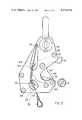
- FIG. 1is an elevation of the hook assembly embodying the invention with parts broken away to show the lanyard and spring connections to the cam and release latch in the locked position of the assembly. This view includes a fragmentary sectional view of the davit ring.
- FIG. 2is an end view of the hook assembly taken along the line 2--2 of FIG. 1 and includes a fragmentary view of the davit ring.
- FIG. 3is an elevation like FIG. 1 but showing the hook assembly while being armed by pulling the lanyard and disengaging the release latch from the cam.
- FIG. 4is a view like FIG. 3 showing the hook assembly in the armed condition with the cam ejecting surface partially ejecting the davit ring.
- FIG. 5is a view like FIG. 4 showing the cam ejecting surface after ejection of the davit ring from the hook assembly.
- FIGS. 1 and 2An automatic hook assembly 10 is shown in FIGS. 1 and 2 in the locked condition.
- a davit ring 11is shown supported in hook retaining eye 12 of the assembly 10 with a locking jaw 14 in a locking position for retaining the ring in the eye.
- the hook assembly 10has a hook body or frame 16 which includes parallel side plates 18 and 20 held in spaced relation by screws 22 extending through side plate 18 and threaded in side plate 20. Cylindrical spacers 24 are positioned around the screws 22 and between the side plates 18 and 20 providing a slot 26 between the side plates. A hook supporting portion 28 of the assembly 10 has aligned holes in the side plates 18 and 20 for receiving a pin 30 of a shackle 32 suitable for fastening to the fall of the life raft davit (not shown).
- a shackle spacer 34 having a hole for the shackle pin 30 and having a thickness the same as the width of the slot 26is disposed between the side plates 18 and 20 with a hole in the shackle spacer coaxial with the holes in the side plates.
- the shackle spacer 34may be secured in place by screws 36 extending through the side plate 18, the shackle spacer 34 and threaded in the side plate 20.
- a hook portion 38 of the hook assembly 10is disposed at a spaced-apart position from the hook supporting portion 28 and has stationary hook jaws 40 and 42 on side plates 18 and 20, respectively.
- a locking and ejecting cam 44is pivotally mounted on a bushing 45 or other friction reducing member supported on a screw 46 positioned between the side plates 18 and 20 on the frame 16 between the hook portion 38 and hook supporting portion 28.
- the screw 46extends through the side plate 18 and is threaded in the side plate 20.
- the cam 44includes the locking jaw 14 which is movable from a locked position shown in FIG. 1 to the released position shown in FIG. 5.
- the cam 44also includes an ejecting surface 48 which is movable from a retracted position shown in FIG. 1 to an ejecting position shown in FIG. 5.
- the cam 44is held in the locking position with the locking jaw 14 depressed as shown in FIG. 1 by a releasable latch 50 pivotally mounted between the side plates 18 and 20 on a bushing 52 supported by a screw 54.
- the latch 50has a locking edge 56 engageable with an edge surface 58 of the cam 44 to the lock the locking jaw 14 in the locking position.
- the locking edge 56may have an indentation 60 which is engaged by a projection 62 on the edge surface 58 of the cam.
- the side plates 18 and 20, the cam 44 and latch 50are preferably of steel or other suitable high strength material.
- the latch 50is held in the locking position relative to the cam 44 by resilient means such as a coil spring 64 fastened at one end to a post 66 mounted on the edge of the cam and a post 68 mounted on the edge of the latch.
- a flexible elongated actuating membersuch as a lanyard 70 of steel cable is attached to the latch 50 as by passing the cable through a hole in the post 68 and having stops 72 swaged at either side of the post.
- the lanyard 70may also extend through the coil spring 64 and a hole in the post 66 to an end stop 74 swaged on the end of the lanyard.
- the minimum distance the end stop 74 can be spaced from the post 66is the distance required to permit the release latch 50 to become disengaged from the cam 44 as shown in FIG. 3 while the cam ejecting surface 48 is in engagement with the davit ring 11 as shown in FIG. 3.
- the shackle 32is fastened to the davit fall (not shown) and the davit ring 11 is locked in place by the locking jaw 14 as shown in FIGS. 1 and 2.
- the releasable latch 50is held by the coil spring 64 against the cam 44 with the projection 62 on the cam edge surface 58 in engagement with the indentation 60 in the locking edge 56 of the latch.
- the hook assembly 10is shown with the lanyard 70 pulled to disengage the latch 50 from the cam 44 with the davit ring 11 retained in position by the raft load.
- the hook assembly 10is armed for ejection of the ring 11 and upon release of the the lanyard 70, the spring 64 returns the latch 50 to a position with the locking edge 56 in sliding engagement with another edge of the cam 44 as shown in FIG. 4.
- the cam ejecting surface 48is urged against the davit ring 11 and as the load is released, the ring is pushed out of the hook retaining eye 12 as shown in FIG. 4. This does not occur until the raft has landed on the water and the raft load is zero or a very small amount.
- the hook assembly 10is shown in the condition after the cam ejecting surface 48 has urged the davit ring 11 over the hook jaws 40 and 42 and out of the hook retaining eye 12 so that the life raft may float on the water and not be jerked or pulled by the davit fall fastened to the ship or oil well platform.
- the cam ejecting surface 48has a predetermined slope in the ring ejecting position for sliding the ring 11 out of the load retaining eye 12 by gravity.
- the lanyard end stop 74is spaced a substantial distance from the post 66 as the spring 64 is contracted.
- the lanyard 70can be pulled through the post 66 until the stop 74 engages the post at which time the cam 44 will be rotated to the position shown in FIG. 5. This movement is also made possible by the rotation of the latch 50 downward to permit rotation of the cam 44 to the ejecting position as shown in FIG. 5.
- the hook assembly 10After the hook assembly 10 has been removed from the davit ring 11 of one raft it may be lifted by a davit and locked on a ring of another raft. This is accomplished by manually inserting the ring 11 which is not under load into the hook retaining eye 12, as shown in FIG. 4, and then pulling the locking jaw 14 towards the hook jaws 40 and 42 to the position shown in FIG. 1 where the projection 62 on the cam edge surface 58 engages the indentation 60 in the locking edge 56 of the releasable latch 50. The hook assembly 10 is then ready for use in the manner described hereinabove.
Landscapes
- Engineering & Computer Science (AREA)
- General Engineering & Computer Science (AREA)
- Mechanical Engineering (AREA)
- Hooks, Suction Cups, And Attachment By Adhesive Means (AREA)
Abstract
Description
Claims (9)
Priority Applications (2)
| Application Number | Priority Date | Filing Date | Title |
|---|---|---|---|
| US06/331,120US4379579A (en) | 1981-12-16 | 1981-12-16 | Automatic locking and ejecting hook assembly |
| EP82111584AEP0081844B1 (en) | 1981-12-16 | 1982-12-14 | Automatic locking and ejecting hook assembly |
Applications Claiming Priority (1)
| Application Number | Priority Date | Filing Date | Title |
|---|---|---|---|
| US06/331,120US4379579A (en) | 1981-12-16 | 1981-12-16 | Automatic locking and ejecting hook assembly |
Publications (1)
| Publication Number | Publication Date |
|---|---|
| US4379579Atrue US4379579A (en) | 1983-04-12 |
Family
ID=23292694
Family Applications (1)
| Application Number | Title | Priority Date | Filing Date |
|---|---|---|---|
| US06/331,120Expired - LifetimeUS4379579A (en) | 1981-12-16 | 1981-12-16 | Automatic locking and ejecting hook assembly |
Country Status (2)
| Country | Link |
|---|---|
| US (1) | US4379579A (en) |
| EP (1) | EP0081844B1 (en) |
Cited By (28)
| Publication number | Priority date | Publication date | Assignee | Title |
|---|---|---|---|---|
| US4471511A (en)* | 1982-03-11 | 1984-09-18 | Rfd Limited | Releasable connector |
| US4537434A (en)* | 1984-05-02 | 1985-08-27 | The United States Of America As Represented By The Secretary Of The Navy | Adjustable self-releasing hook |
| US4767144A (en)* | 1985-06-19 | 1988-08-30 | Hoernberg Gunnar | Hook assembly |
| EP0290107A1 (en)* | 1987-05-07 | 1988-11-09 | Rockwool Lapinus B.V. | Hoist system for hinged structural members and a hinge and hoisting element therefor |
| US4977647A (en)* | 1989-10-27 | 1990-12-18 | D.B. Industries, Inc. | Double locking snap hook |
| US20040094982A1 (en)* | 2002-11-18 | 2004-05-20 | Neufeldt Roy E. | Truss hook |
| US20040222647A1 (en)* | 2003-05-07 | 2004-11-11 | Smith Kelly K. | Low profile mechanical assist hood latch |
| US6957979B2 (en) | 2001-06-01 | 2005-10-25 | Southco, Inc. | Latch with bail-type mounting |
| US20070055110A1 (en)* | 2005-09-07 | 2007-03-08 | West Coast Surgical, Llc. | Connector with safety latch for a surgical retractor |
| US20070055109A1 (en)* | 2005-09-07 | 2007-03-08 | West Coast Surgical, Llc | Connector for a surgical retractor |
| US20090066099A1 (en)* | 2002-11-18 | 2009-03-12 | Neufeldt Roy E | Truss hook |
| US20090124861A1 (en)* | 2005-02-07 | 2009-05-14 | Peter Edward Fetzer | Push-button activated grasper for surgical retractor |
| WO2009130404A1 (en) | 2008-03-26 | 2009-10-29 | Zedel | Apparatus for securing rescue operations by helihoisting |
| WO2010003761A1 (en)* | 2008-06-16 | 2010-01-14 | Nadiro A/S | A coupling |
| WO2010145721A1 (en)* | 2009-06-15 | 2010-12-23 | Nadiro A/S | A coupling |
| WO2011027378A1 (en)* | 2009-09-02 | 2011-03-10 | C.M.V.I. Group S.R.L. | Device for hooking/unhooking loads to be lifted |
| US7976085B1 (en) | 2008-02-05 | 2011-07-12 | Michael Neaton | Lift member—safety latch combination |
| US20120150185A1 (en)* | 2010-12-09 | 2012-06-14 | Extraortho, Inc. | Revolving Lock for External Fixation Clamps |
| RU2474528C2 (en)* | 2011-01-20 | 2013-02-10 | Государственное образовательное учреждение высшего профессионального образования "Южно-Российский государственный университет экономики и сервиса" (ГОУ ВПО "ЮРГУЭС") | Suspended automatic clamping catcher |
| US8523253B1 (en) | 2012-04-05 | 2013-09-03 | Konecranes Plc. | Lifting assembly |
| US8539652B2 (en) | 2011-09-23 | 2013-09-24 | Ralph Robin Richardson | Latching fastener with locking feature |
| US8752254B2 (en) | 2012-02-28 | 2014-06-17 | D B Industries, Llc | Snap hook |
| US8813549B1 (en)* | 2013-03-18 | 2014-08-26 | Chen Yuan Pao | Testing apparatus for off-load and on-load unhooking simulation of the release device of a closed lifeboat |
| JP2015011802A (en)* | 2013-06-27 | 2015-01-19 | 中国電力株式会社 | High tension tensile insulator |
| US9707419B2 (en) | 2014-10-08 | 2017-07-18 | D B Industries, Llc | Snap hook |
| CN108239917A (en)* | 2018-02-02 | 2018-07-03 | 珠海及力高空作业设备有限公司 | A kind of Zhongting splices the bridge that floats |
| CN109625184A (en)* | 2018-12-19 | 2019-04-16 | 中国舰船研究设计中心 | A kind of canoe captures release device and method automatically |
| WO2020033515A1 (en)* | 2018-08-07 | 2020-02-13 | Hester Ronald J | Pelican hook |
Families Citing this family (5)
| Publication number | Priority date | Publication date | Assignee | Title |
|---|---|---|---|---|
| AU625004B2 (en)* | 1989-10-23 | 1992-06-25 | Cetram Pty Limited | Clutches for use with lifting anchors |
| FR2704037B1 (en)* | 1993-04-13 | 1995-07-13 | Ferrato Gerard | Quick and remote hooking and unhooking device. |
| US8544153B2 (en)* | 2011-09-09 | 2013-10-01 | Magpul Industries Corp | Lockable snap-clip fastener |
| CN104505793B (en)* | 2014-12-15 | 2017-07-28 | 中国南方电网有限责任公司超高压输电公司梧州局 | A kind of analog insulation substring hangs gold utensil |
| DE102023126246A1 (en)* | 2023-09-27 | 2025-03-27 | Kiekert Aktiengesellschaft | Device for holding, lifting and/or carrying a load |
Citations (7)
| Publication number | Priority date | Publication date | Assignee | Title |
|---|---|---|---|---|
| US1576197A (en)* | 1925-02-06 | 1926-03-09 | David C Kuffel | Safety hook |
| US1879168A (en)* | 1931-07-10 | 1932-09-27 | North & Judd Mfg Co | Safety snap hook |
| US2413392A (en)* | 1945-02-07 | 1946-12-31 | Veverka Rudolph | Clasp |
| US2595450A (en)* | 1949-11-21 | 1952-05-06 | Coffing Hoist Company | Releasing type hook |
| US3144697A (en)* | 1960-01-14 | 1964-08-18 | Rosenberg Herbert Olof | Safety belt buckle for vehicle occupants |
| US3539217A (en)* | 1968-10-15 | 1970-11-10 | Otto E Szekely | Self-releasing cargo hook |
| US3918758A (en)* | 1974-07-18 | 1975-11-11 | Aeroquip Corp | Remotely releasable self-latching snap hook |
Family Cites Families (5)
| Publication number | Priority date | Publication date | Assignee | Title |
|---|---|---|---|---|
| US1622971A (en)* | 1926-07-21 | 1927-03-29 | Porter George Newton | Safety hook |
| US2613101A (en)* | 1950-10-17 | 1952-10-07 | Roberson Claude Mcjunis | Hook latch operating mechanism |
| GB717351A (en)* | 1952-03-31 | 1954-10-27 | Geoffrey Haslewood Cooke | Improvements relating to load-bearing hooks |
| GB910904A (en)* | 1960-01-28 | 1962-11-21 | Rfd Co Ltd | Improved releasable support mechanism for supporting a liferaft or like load |
| US3038753A (en)* | 1960-08-29 | 1962-06-12 | John J Seager | Hoist line grab hook |
- 1981
- 1981-12-16USUS06/331,120patent/US4379579A/ennot_activeExpired - Lifetime
- 1982
- 1982-12-14EPEP82111584Apatent/EP0081844B1/ennot_activeExpired
Patent Citations (7)
| Publication number | Priority date | Publication date | Assignee | Title |
|---|---|---|---|---|
| US1576197A (en)* | 1925-02-06 | 1926-03-09 | David C Kuffel | Safety hook |
| US1879168A (en)* | 1931-07-10 | 1932-09-27 | North & Judd Mfg Co | Safety snap hook |
| US2413392A (en)* | 1945-02-07 | 1946-12-31 | Veverka Rudolph | Clasp |
| US2595450A (en)* | 1949-11-21 | 1952-05-06 | Coffing Hoist Company | Releasing type hook |
| US3144697A (en)* | 1960-01-14 | 1964-08-18 | Rosenberg Herbert Olof | Safety belt buckle for vehicle occupants |
| US3539217A (en)* | 1968-10-15 | 1970-11-10 | Otto E Szekely | Self-releasing cargo hook |
| US3918758A (en)* | 1974-07-18 | 1975-11-11 | Aeroquip Corp | Remotely releasable self-latching snap hook |
Cited By (52)
| Publication number | Priority date | Publication date | Assignee | Title |
|---|---|---|---|---|
| US4471511A (en)* | 1982-03-11 | 1984-09-18 | Rfd Limited | Releasable connector |
| US4537434A (en)* | 1984-05-02 | 1985-08-27 | The United States Of America As Represented By The Secretary Of The Navy | Adjustable self-releasing hook |
| US4767144A (en)* | 1985-06-19 | 1988-08-30 | Hoernberg Gunnar | Hook assembly |
| EP0290107A1 (en)* | 1987-05-07 | 1988-11-09 | Rockwool Lapinus B.V. | Hoist system for hinged structural members and a hinge and hoisting element therefor |
| US4977647A (en)* | 1989-10-27 | 1990-12-18 | D.B. Industries, Inc. | Double locking snap hook |
| US6957979B2 (en) | 2001-06-01 | 2005-10-25 | Southco, Inc. | Latch with bail-type mounting |
| US20040094982A1 (en)* | 2002-11-18 | 2004-05-20 | Neufeldt Roy E. | Truss hook |
| US20090066099A1 (en)* | 2002-11-18 | 2009-03-12 | Neufeldt Roy E | Truss hook |
| US7059644B2 (en)* | 2002-11-18 | 2006-06-13 | Neufeldt Roy E | Truss gripping hook |
| US20060208514A1 (en)* | 2002-11-18 | 2006-09-21 | Neufeldt Roy E | Truss hook |
| US7422257B2 (en)* | 2002-11-18 | 2008-09-09 | Neufeldt Roy E | Truss gripping hook |
| US7325846B2 (en) | 2003-05-07 | 2008-02-05 | Hewlett-Packard Development Company, L.P. | Low profile mechanical assist hood latch |
| US20040222647A1 (en)* | 2003-05-07 | 2004-11-11 | Smith Kelly K. | Low profile mechanical assist hood latch |
| US20080061563A1 (en)* | 2003-05-07 | 2008-03-13 | Hewlett-Packard Development Company, L.P. | Low profile mechanical assist hood latch |
| US7614672B2 (en) | 2003-05-07 | 2009-11-10 | Hewlett-Packard Development Company, L.P. | Low profile mechanical assist hood latch |
| US8357087B2 (en)* | 2005-02-07 | 2013-01-22 | Peter Edward Fetzer | Push-button activated grasper for surgical retractor |
| US20090124861A1 (en)* | 2005-02-07 | 2009-05-14 | Peter Edward Fetzer | Push-button activated grasper for surgical retractor |
| US7569014B2 (en) | 2005-09-07 | 2009-08-04 | West Coast Surgical, Llc | Connector for a surgical retractor |
| US7588537B2 (en) | 2005-09-07 | 2009-09-15 | West Coast Surgical, Llc. | Connector with safety latch for a surgical retractor |
| US20070055110A1 (en)* | 2005-09-07 | 2007-03-08 | West Coast Surgical, Llc. | Connector with safety latch for a surgical retractor |
| US20070055109A1 (en)* | 2005-09-07 | 2007-03-08 | West Coast Surgical, Llc | Connector for a surgical retractor |
| US7976085B1 (en) | 2008-02-05 | 2011-07-12 | Michael Neaton | Lift member—safety latch combination |
| WO2009130404A1 (en) | 2008-03-26 | 2009-10-29 | Zedel | Apparatus for securing rescue operations by helihoisting |
| US8226138B2 (en) | 2008-03-26 | 2012-07-24 | Zedel | Apparatus for securing rescue operations by helihoisting |
| US20110042984A1 (en)* | 2008-03-26 | 2011-02-24 | Zedel | Apparatus for securing rescue operations by helihoisting |
| US20110132253A1 (en)* | 2008-06-16 | 2011-06-09 | Bent Nielsen | Coupling |
| WO2010003761A1 (en)* | 2008-06-16 | 2010-01-14 | Nadiro A/S | A coupling |
| CN102119100A (en)* | 2008-06-16 | 2011-07-06 | 纳迪罗股份公司 | connector |
| CN102119100B (en)* | 2008-06-16 | 2014-04-02 | 纳迪罗股份公司 | connector |
| US8667921B2 (en) | 2008-06-16 | 2014-03-11 | Nadiro A/S | Coupling |
| US8561566B2 (en) | 2008-06-16 | 2013-10-22 | Nadiro A/S | Coupling |
| WO2010145721A1 (en)* | 2009-06-15 | 2010-12-23 | Nadiro A/S | A coupling |
| CN102803061A (en)* | 2009-06-15 | 2012-11-28 | 纳迪罗股份公司 | A coupling |
| CN102803061B (en)* | 2009-06-15 | 2015-03-11 | 纳迪罗股份公司 | A coupling |
| WO2011027378A1 (en)* | 2009-09-02 | 2011-03-10 | C.M.V.I. Group S.R.L. | Device for hooking/unhooking loads to be lifted |
| US9186179B2 (en)* | 2010-12-09 | 2015-11-17 | Zimmer, Inc. | Revolving lock for external fixation clamps |
| US20120150185A1 (en)* | 2010-12-09 | 2012-06-14 | Extraortho, Inc. | Revolving Lock for External Fixation Clamps |
| RU2474528C2 (en)* | 2011-01-20 | 2013-02-10 | Государственное образовательное учреждение высшего профессионального образования "Южно-Российский государственный университет экономики и сервиса" (ГОУ ВПО "ЮРГУЭС") | Suspended automatic clamping catcher |
| US8539652B2 (en) | 2011-09-23 | 2013-09-24 | Ralph Robin Richardson | Latching fastener with locking feature |
| US8752254B2 (en) | 2012-02-28 | 2014-06-17 | D B Industries, Llc | Snap hook |
| US9328765B2 (en) | 2012-02-28 | 2016-05-03 | D B Industries, Llc | Snap hook |
| US8833822B2 (en) | 2012-04-05 | 2014-09-16 | Konecranes Plc. | Lifting assembly |
| US9061866B2 (en) | 2012-04-05 | 2015-06-23 | Konecranes Plc | Lifting assembly |
| US8523253B1 (en) | 2012-04-05 | 2013-09-03 | Konecranes Plc. | Lifting assembly |
| US20140260580A1 (en)* | 2013-03-18 | 2014-09-18 | Chen Yuan Pao | Testing apparatus for off-load and on-load unhooking simulation of the release device of a closed lifeboat |
| US8813549B1 (en)* | 2013-03-18 | 2014-08-26 | Chen Yuan Pao | Testing apparatus for off-load and on-load unhooking simulation of the release device of a closed lifeboat |
| JP2015011802A (en)* | 2013-06-27 | 2015-01-19 | 中国電力株式会社 | High tension tensile insulator |
| US9707419B2 (en) | 2014-10-08 | 2017-07-18 | D B Industries, Llc | Snap hook |
| US10086221B2 (en) | 2014-10-08 | 2018-10-02 | D B Industries, Llc | Snap hook |
| CN108239917A (en)* | 2018-02-02 | 2018-07-03 | 珠海及力高空作业设备有限公司 | A kind of Zhongting splices the bridge that floats |
| WO2020033515A1 (en)* | 2018-08-07 | 2020-02-13 | Hester Ronald J | Pelican hook |
| CN109625184A (en)* | 2018-12-19 | 2019-04-16 | 中国舰船研究设计中心 | A kind of canoe captures release device and method automatically |
Also Published As
| Publication number | Publication date |
|---|---|
| EP0081844B1 (en) | 1985-10-02 |
| EP0081844A1 (en) | 1983-06-22 |
Similar Documents
| Publication | Publication Date | Title |
|---|---|---|
| US4379579A (en) | Automatic locking and ejecting hook assembly | |
| US4471511A (en) | Releasable connector | |
| EP0743246A1 (en) | Mechanism for arming, disarming and activating airplane emergency slide evacuation systems | |
| GB1568571A (en) | Release hook assemblies | |
| US4303213A (en) | Tow plate | |
| US4281867A (en) | Disengaging apparatus | |
| KR20150020179A (en) | Inline mechanical disconnect device | |
| KR20110031325A (en) | Coupling | |
| EP2338784B1 (en) | Lifeboat hoisting and lowering apparatus provided with a fall preventing device | |
| US5205600A (en) | Automatic release coupling | |
| US3865333A (en) | Quick release open link | |
| US5078073A (en) | Method and apparatus for a lifeboat safety strop | |
| US4198918A (en) | Semi-automatic bailer plug | |
| US3009729A (en) | Tension type release coupler | |
| US4610474A (en) | Lifeboat release hook | |
| US3986745A (en) | Grabber | |
| US3781055A (en) | Releasable coupling | |
| US2429769A (en) | Self-locking hook | |
| EP0042021A1 (en) | Disengaging apparatus | |
| US4537434A (en) | Adjustable self-releasing hook | |
| US3044812A (en) | Cable anchor clevis | |
| US3733101A (en) | Helo recovery system tongs | |
| JPH072390Y2 (en) | Automatic disengagement device used for buoys for warning of marine accidents | |
| US3132357A (en) | Launching device | |
| US2965409A (en) | Release hook |
Legal Events
| Date | Code | Title | Description |
|---|---|---|---|
| AS | Assignment | Owner name:BF GOODRICH COMPANY THE, 277 PARK AVE., NEW YORK, Free format text:ASSIGNMENT OF ASSIGNORS INTEREST.;ASSIGNORS:MAHAN, RICHARD S.;TRITT, PAUL G.;WARD, JAMES H. JR.;REEL/FRAME:003957/0659;SIGNING DATES FROM 19811119 TO 19811130 | |
| STCF | Information on status: patent grant | Free format text:PATENTED CASE | |
| MAFP | Maintenance fee payment | Free format text:PAYMENT OF MAINTENANCE FEE, 4TH YEAR, PL 96-517 (ORIGINAL EVENT CODE: M170); ENTITY STATUS OF PATENT OWNER: LARGE ENTITY Year of fee payment:4 | |
| AS | Assignment | Owner name:SMR TECHNOLOGIES, INC., OHIO Free format text:ASSIGNMENT OF ASSIGNORS INTEREST.;ASSIGNOR:B.F. GOODRICH COMPANY, THE;REEL/FRAME:005029/0510 Effective date:19890227 | |
| FEPP | Fee payment procedure | Free format text:PAYOR NUMBER ASSIGNED (ORIGINAL EVENT CODE: ASPN); ENTITY STATUS OF PATENT OWNER: LARGE ENTITY | |
| MAFP | Maintenance fee payment | Free format text:PAYMENT OF MAINTENANCE FEE, 8TH YEAR, PL 96-517 (ORIGINAL EVENT CODE: M171); ENTITY STATUS OF PATENT OWNER: LARGE ENTITY Year of fee payment:8 | |
| MAFP | Maintenance fee payment | Free format text:PAYMENT OF MAINTENANCE FEE, 12TH YEAR, LARGE ENTITY (ORIGINAL EVENT CODE: M185); ENTITY STATUS OF PATENT OWNER: LARGE ENTITY Year of fee payment:12 | |
| AS | Assignment | Owner name:INFLATABLE SURVIVAL SYSTEMS INC., OHIO Free format text:ASSIGNMENT OF ASSIGNORS INTEREST;ASSIGNOR:SMR TECHNOLOGIES, INC.;REEL/FRAME:008000/0221 Effective date:19960603 | |
| AS | Assignment | Owner name:INFLATABLE SURVIVAL SYSTEMS, INC., OHIO Free format text:ASSIGNMENT OF ASSIGNORS INTEREST;ASSIGNOR:SMR TECHNOLOGIES, INC.;REEL/FRAME:008345/0449 Effective date:19970204 |