US4379452A - Prepackaged, self-contained fluid circuit module - Google Patents
Prepackaged, self-contained fluid circuit moduleDownload PDFInfo
- Publication number
- US4379452A US4379452AUS06/100,975US10097579AUS4379452AUS 4379452 AUS4379452 AUS 4379452AUS 10097579 AUS10097579 AUS 10097579AUS 4379452 AUS4379452 AUS 4379452A
- Authority
- US
- United States
- Prior art keywords
- conduit means
- fluid
- prepackaged
- self
- circuit module
- Prior art date
- Legal status (The legal status is an assumption and is not a legal conclusion. Google has not performed a legal analysis and makes no representation as to the accuracy of the status listed.)
- Expired - Lifetime
Links
Images


Classifications
- A—HUMAN NECESSITIES
- A61—MEDICAL OR VETERINARY SCIENCE; HYGIENE
- A61M—DEVICES FOR INTRODUCING MEDIA INTO, OR ONTO, THE BODY; DEVICES FOR TRANSDUCING BODY MEDIA OR FOR TAKING MEDIA FROM THE BODY; DEVICES FOR PRODUCING OR ENDING SLEEP OR STUPOR
- A61M1/00—Suction or pumping devices for medical purposes; Devices for carrying-off, for treatment of, or for carrying-over, body-liquids; Drainage systems
- A61M1/36—Other treatment of blood in a by-pass of the natural circulatory system, e.g. temperature adaptation, irradiation ; Extra-corporeal blood circuits
- A61M1/3693—Other treatment of blood in a by-pass of the natural circulatory system, e.g. temperature adaptation, irradiation ; Extra-corporeal blood circuits using separation based on different densities of components, e.g. centrifuging
- A—HUMAN NECESSITIES
- A61—MEDICAL OR VETERINARY SCIENCE; HYGIENE
- A61M—DEVICES FOR INTRODUCING MEDIA INTO, OR ONTO, THE BODY; DEVICES FOR TRANSDUCING BODY MEDIA OR FOR TAKING MEDIA FROM THE BODY; DEVICES FOR PRODUCING OR ENDING SLEEP OR STUPOR
- A61M1/00—Suction or pumping devices for medical purposes; Devices for carrying-off, for treatment of, or for carrying-over, body-liquids; Drainage systems
- A61M1/02—Blood transfusion apparatus
- A61M1/0209—Multiple bag systems for separating or storing blood components
- A—HUMAN NECESSITIES
- A61—MEDICAL OR VETERINARY SCIENCE; HYGIENE
- A61M—DEVICES FOR INTRODUCING MEDIA INTO, OR ONTO, THE BODY; DEVICES FOR TRANSDUCING BODY MEDIA OR FOR TAKING MEDIA FROM THE BODY; DEVICES FOR PRODUCING OR ENDING SLEEP OR STUPOR
- A61M1/00—Suction or pumping devices for medical purposes; Devices for carrying-off, for treatment of, or for carrying-over, body-liquids; Drainage systems
- A61M1/36—Other treatment of blood in a by-pass of the natural circulatory system, e.g. temperature adaptation, irradiation ; Extra-corporeal blood circuits
- A61M1/3621—Extra-corporeal blood circuits
- A61M1/3622—Extra-corporeal blood circuits with a cassette forming partially or totally the blood circuit
- A61M1/36226—Constructional details of cassettes, e.g. specific details on material or shape
- A61M1/362263—Details of incorporated filters
- A61M1/362264—Details of incorporated filters the filter being a blood filter
- A—HUMAN NECESSITIES
- A61—MEDICAL OR VETERINARY SCIENCE; HYGIENE
- A61M—DEVICES FOR INTRODUCING MEDIA INTO, OR ONTO, THE BODY; DEVICES FOR TRANSDUCING BODY MEDIA OR FOR TAKING MEDIA FROM THE BODY; DEVICES FOR PRODUCING OR ENDING SLEEP OR STUPOR
- A61M1/00—Suction or pumping devices for medical purposes; Devices for carrying-off, for treatment of, or for carrying-over, body-liquids; Drainage systems
- A61M1/36—Other treatment of blood in a by-pass of the natural circulatory system, e.g. temperature adaptation, irradiation ; Extra-corporeal blood circuits
- A61M1/3621—Extra-corporeal blood circuits
- A61M1/3622—Extra-corporeal blood circuits with a cassette forming partially or totally the blood circuit
- A61M1/36226—Constructional details of cassettes, e.g. specific details on material or shape
- A61M1/362266—Means for adding solutions or substances to the blood
- A—HUMAN NECESSITIES
- A61—MEDICAL OR VETERINARY SCIENCE; HYGIENE
- A61M—DEVICES FOR INTRODUCING MEDIA INTO, OR ONTO, THE BODY; DEVICES FOR TRANSDUCING BODY MEDIA OR FOR TAKING MEDIA FROM THE BODY; DEVICES FOR PRODUCING OR ENDING SLEEP OR STUPOR
- A61M1/00—Suction or pumping devices for medical purposes; Devices for carrying-off, for treatment of, or for carrying-over, body-liquids; Drainage systems
- A61M1/36—Other treatment of blood in a by-pass of the natural circulatory system, e.g. temperature adaptation, irradiation ; Extra-corporeal blood circuits
- A61M1/3693—Other treatment of blood in a by-pass of the natural circulatory system, e.g. temperature adaptation, irradiation ; Extra-corporeal blood circuits using separation based on different densities of components, e.g. centrifuging
- A61M1/3696—Other treatment of blood in a by-pass of the natural circulatory system, e.g. temperature adaptation, irradiation ; Extra-corporeal blood circuits using separation based on different densities of components, e.g. centrifuging with means for adding or withdrawing liquid substances during the centrifugation, e.g. continuous centrifugation
- A—HUMAN NECESSITIES
- A61—MEDICAL OR VETERINARY SCIENCE; HYGIENE
- A61M—DEVICES FOR INTRODUCING MEDIA INTO, OR ONTO, THE BODY; DEVICES FOR TRANSDUCING BODY MEDIA OR FOR TAKING MEDIA FROM THE BODY; DEVICES FOR PRODUCING OR ENDING SLEEP OR STUPOR
- A61M1/00—Suction or pumping devices for medical purposes; Devices for carrying-off, for treatment of, or for carrying-over, body-liquids; Drainage systems
- A61M1/36—Other treatment of blood in a by-pass of the natural circulatory system, e.g. temperature adaptation, irradiation ; Extra-corporeal blood circuits
- A61M1/3621—Extra-corporeal blood circuits
- A61M1/3622—Extra-corporeal blood circuits with a cassette forming partially or totally the blood circuit
- A61M1/36224—Extra-corporeal blood circuits with a cassette forming partially or totally the blood circuit with sensing means or components thereof
- A—HUMAN NECESSITIES
- A61—MEDICAL OR VETERINARY SCIENCE; HYGIENE
- A61M—DEVICES FOR INTRODUCING MEDIA INTO, OR ONTO, THE BODY; DEVICES FOR TRANSDUCING BODY MEDIA OR FOR TAKING MEDIA FROM THE BODY; DEVICES FOR PRODUCING OR ENDING SLEEP OR STUPOR
- A61M1/00—Suction or pumping devices for medical purposes; Devices for carrying-off, for treatment of, or for carrying-over, body-liquids; Drainage systems
- A61M1/36—Other treatment of blood in a by-pass of the natural circulatory system, e.g. temperature adaptation, irradiation ; Extra-corporeal blood circuits
- A61M1/3621—Extra-corporeal blood circuits
- A61M1/3622—Extra-corporeal blood circuits with a cassette forming partially or totally the blood circuit
- A61M1/36225—Extra-corporeal blood circuits with a cassette forming partially or totally the blood circuit with blood pumping means or components thereof
- A—HUMAN NECESSITIES
- A61—MEDICAL OR VETERINARY SCIENCE; HYGIENE
- A61M—DEVICES FOR INTRODUCING MEDIA INTO, OR ONTO, THE BODY; DEVICES FOR TRANSDUCING BODY MEDIA OR FOR TAKING MEDIA FROM THE BODY; DEVICES FOR PRODUCING OR ENDING SLEEP OR STUPOR
- A61M1/00—Suction or pumping devices for medical purposes; Devices for carrying-off, for treatment of, or for carrying-over, body-liquids; Drainage systems
- A61M1/36—Other treatment of blood in a by-pass of the natural circulatory system, e.g. temperature adaptation, irradiation ; Extra-corporeal blood circuits
- A61M1/3621—Extra-corporeal blood circuits
- A61M1/3622—Extra-corporeal blood circuits with a cassette forming partially or totally the blood circuit
- A61M1/36226—Constructional details of cassettes, e.g. specific details on material or shape
- A61M1/362261—Constructional details of cassettes, e.g. specific details on material or shape at least one cassette surface or portion thereof being flexible, e.g. the cassette having a rigid base portion with preformed channels and being covered with a foil
- A—HUMAN NECESSITIES
- A61—MEDICAL OR VETERINARY SCIENCE; HYGIENE
- A61M—DEVICES FOR INTRODUCING MEDIA INTO, OR ONTO, THE BODY; DEVICES FOR TRANSDUCING BODY MEDIA OR FOR TAKING MEDIA FROM THE BODY; DEVICES FOR PRODUCING OR ENDING SLEEP OR STUPOR
- A61M1/00—Suction or pumping devices for medical purposes; Devices for carrying-off, for treatment of, or for carrying-over, body-liquids; Drainage systems
- A61M1/36—Other treatment of blood in a by-pass of the natural circulatory system, e.g. temperature adaptation, irradiation ; Extra-corporeal blood circuits
- A61M1/3621—Extra-corporeal blood circuits
- A61M1/3622—Extra-corporeal blood circuits with a cassette forming partially or totally the blood circuit
- A61M1/36226—Constructional details of cassettes, e.g. specific details on material or shape
- A61M1/362262—Details of incorporated reservoirs
- A—HUMAN NECESSITIES
- A61—MEDICAL OR VETERINARY SCIENCE; HYGIENE
- A61M—DEVICES FOR INTRODUCING MEDIA INTO, OR ONTO, THE BODY; DEVICES FOR TRANSDUCING BODY MEDIA OR FOR TAKING MEDIA FROM THE BODY; DEVICES FOR PRODUCING OR ENDING SLEEP OR STUPOR
- A61M1/00—Suction or pumping devices for medical purposes; Devices for carrying-off, for treatment of, or for carrying-over, body-liquids; Drainage systems
- A61M1/36—Other treatment of blood in a by-pass of the natural circulatory system, e.g. temperature adaptation, irradiation ; Extra-corporeal blood circuits
- A61M1/3621—Extra-corporeal blood circuits
- A61M1/3622—Extra-corporeal blood circuits with a cassette forming partially or totally the blood circuit
- A61M1/36226—Constructional details of cassettes, e.g. specific details on material or shape
- A61M1/362265—Details of valves
- A—HUMAN NECESSITIES
- A61—MEDICAL OR VETERINARY SCIENCE; HYGIENE
- A61M—DEVICES FOR INTRODUCING MEDIA INTO, OR ONTO, THE BODY; DEVICES FOR TRANSDUCING BODY MEDIA OR FOR TAKING MEDIA FROM THE BODY; DEVICES FOR PRODUCING OR ENDING SLEEP OR STUPOR
- A61M1/00—Suction or pumping devices for medical purposes; Devices for carrying-off, for treatment of, or for carrying-over, body-liquids; Drainage systems
- A61M1/36—Other treatment of blood in a by-pass of the natural circulatory system, e.g. temperature adaptation, irradiation ; Extra-corporeal blood circuits
- A61M1/3621—Extra-corporeal blood circuits
- A61M1/3639—Blood pressure control, pressure transducers specially adapted therefor
- A—HUMAN NECESSITIES
- A61—MEDICAL OR VETERINARY SCIENCE; HYGIENE
- A61M—DEVICES FOR INTRODUCING MEDIA INTO, OR ONTO, THE BODY; DEVICES FOR TRANSDUCING BODY MEDIA OR FOR TAKING MEDIA FROM THE BODY; DEVICES FOR PRODUCING OR ENDING SLEEP OR STUPOR
- A61M2205/00—General characteristics of the apparatus
- A61M2205/12—General characteristics of the apparatus with interchangeable cassettes forming partially or totally the fluid circuit
- A61M2205/125—General characteristics of the apparatus with interchangeable cassettes forming partially or totally the fluid circuit with incorporated filters
- A—HUMAN NECESSITIES
- A61—MEDICAL OR VETERINARY SCIENCE; HYGIENE
- A61M—DEVICES FOR INTRODUCING MEDIA INTO, OR ONTO, THE BODY; DEVICES FOR TRANSDUCING BODY MEDIA OR FOR TAKING MEDIA FROM THE BODY; DEVICES FOR PRODUCING OR ENDING SLEEP OR STUPOR
- A61M2205/00—General characteristics of the apparatus
- A61M2205/33—Controlling, regulating or measuring
- A61M2205/3306—Optical measuring means
- A61M2205/331—Optical measuring means used as turbidity change detectors, e.g. for priming-blood or plasma-hemoglubine-interface detection
Definitions
- the present inventionrelates to a monitor and fluid circuit assembly utilized in an apparatus for processing whole blood and more specifically to a compact disposable monitor and fluid circuit assembly for collecting a desired blood component such as platelets.
- Apparatus for carrying out intervivos blood processinghave typically included a separation chamber within which whole blood from a donor is subjected to a centrifugal force. This is typically accomplished in a centrifuge device. Because of differences in densities the various blood components will congregate in different zones at different radial distances from the center of rotation of the separation chamber. Then, collection ports in the chamber are utilized to remove the blood components from the various zones in the separation chamber for storage or recirculation.
- the present inventionprovides a monitor and fluid circuit assembly which can be easily mounted on and connected to a blood processing apparatus and easily detached therefrom for separation of a blood component collection bag, e.g., a platelet bag. Also the assembly is made of inexpenive plastic materials such that the assembly minus the collection bag can be discarded.
- a blood component collection bage.g., a platelet bag.
- the assemblyis made of inexpenive plastic materials such that the assembly minus the collection bag can be discarded.
- the inventionprovides a prepackaged, self-contained fluid circuit module which is selectively movable by an operator into and out of operative association with one or more pump rotors.
- the modulecomprises an array of flexible conduits defining a prearranged fluid circuit, portions of which are carried within the confines of a hollow housing. A preselected portion of some of the conduits extends outwardly of the housing in a predetermined arcuate configuration resiliently biased toward an upright, freestanding position when the module is out of operative association with a pump rotor.
- This arrangementaccommodates operative contact between the outwardly bowed portion and a pump motor when the module is moved into operative association with the pump rotor.
- the outwardly bowed, freestanding portionsare arranged relative to each other to further facilitate only the desired operative contact with the pump rotors.
- a pair of outwardly bowed, freestanding portionsare concentrically positioned to accommodate simultaneous operative contact with a single pump rotor.
- a pair of outwardly bowed, freestanding portionsare positioned in a spaced, noncontiguous relationship to accommodate separate operative contact with a spaced pair of pump rotors.
- the moduleincludes, as an integral part thereof, various containers of fluid and/or various fluid receiving receptacles. This arrangement provides for an essentially "closed" fluid flow system. This further simplifies the handling of complex fluid systems and at the same time protects significant portions of the fluid flow system from contamination with the atmosphere.
- FIG. 1is a perspective view of the apparatus with which the monitor and fluid circuit assembly of the present invention is used.
- FIG. 2is an enlarged perspective view of the upper portion of the apparatus shown in FIG. 1 with the monitor and fluid circuit assembly of the present invention removed.
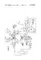
- FIG. 3is a schematic block flow diagram of the fluid circuit of the assembly.
- FIG. 4is a perspective view of the monitor and fluid circuit assembly of the present invention.
- FIG. 5is a fragmentary perspective view of one of the monitor devices of the assembly.
- the apparatus 10includes the monitor and fluid circuit assembly or module of the present invention which is fully shown in, and identified by reference numeral 11 in, FIG. 4.
- the apparatus 10further includes a centrifuge device hidden from view within the cabinet 12.
- the centrifuge deviceis shown schematically in FIG. 3 and identified therein by reference numeral 14.
- reference numeral 14For further details of the construction and operation of the centrifuge device 14, reference is made to co-pending U.S. Pat. No. 4,146,172 filed, entitled: CENTRIFUGAL LIQUID PROCESSING SYSTEM, the disclosure of which patent is incorporated herein by reference.
- the monitor and fluid circuit assembly 11includes a fluid circuit which is generally identified by the reference numeral 16 in FIG. 1 and which is best shown schematically in FIG. 3.
- the fluid circuit 16includes a plurality of flexible plastic tubings which form fluid couplings between various parts of the fluid circuit 16. These tubings are received through a holder or housing 18 which forms part of assembly 11 and which has monitor devices mounted therein.
- the pump 20is referred to as a first or whole blood pump and the pump 22 is referred to as a second or plasma pump.
- the whole blood pump 20is utilized for withdrawing whole blood from a donor whereas the plasma pump 22 is utilized to move plasma from one chamber to another chamber within the centrifuge device 14 (FIG. 3).
- the apparatus 10also includes a display panel 24 including several windows for indicating information useful to an operator.
- an alarm window 26indicates a malfunction of the apparatus 10 or a condition occurring within the fluid circuit 16 of the apparatus 10.
- a window 28indicating the blood component which is being collected
- a window 30indicating volume processed and end point
- a window 32indicating the elapsed time of operation of the apparatus 10, the flow rate of the whole blood and the flow rate of platelet rich plasma.
- buttons 41-47are provided for controlling various phases of operation of the apparatus 10, as well as windows 48 and 49 on the display panel 24 for indicating the hematocrit of the donor.
- the apparatus 10includes a manual control panel 50 which, as best shown in FIG. 2, includes a plurality of knobs and switches for manual operation of the apparatus 10.
- the legends on the manual control panel 50generally identify the various toggle switches and push button switches, the purpose of which will become apparent from the detailed description of the operation of the apparatus 10 set forth below.
- the circuit 16includes a first fluid coupling or tubing 54 adapted to be coupled to a vein in one arm of a donor 52 by means of a hypodermic needle 56 which is rejected into the arm.
- a fluid clamp 58(shown schematically) can be provided on the tubing 54.
- the first tubing 54has associated therewith a solenoid operated clamp 60 forming valve #1.
- the tubing 54then has series coupled thereto an occluded vein monitor device 62 with an associated sensor 63.
- the first tubing 54extends over and forms part of the peristaltic pump 20 and is series coupled to a high pressure monitor device 64 with an associated sensor 65. From the monitor device 64 the first tubing 54 extends into the centrifuge device 14 and to the bottom inlet of a first compartment or receptacle 66 which is identified as a whole blood bag and which defines therein a whole blood separation chamber.
- the receptacle 66has a first outlet 68 at the center thereof adjacent a zone in the receptacle 66 where platelet rich plasma congregates.
- Receptacle 66also has two outlets 70 and 72 at the upper corners thereof where red blood cells congregate.
- Outlet 68provides not only an outlet for platelet rich plasma but also a return inlet for platelet rich plasma which is "contaminated" (mixed) with red blood cells when there is a spillover of red blood cells out of outlet 68.
- the outlet 68 of the first receptacle 66is coupled to a second fluid coupling or tubing 74 which extends to a loop 75 thereof located exterior of the centrifuge device 14 and which loop extends about and forms part of the peristaltic pump 22. Also, positioned adjacent a transparent or translucent section of the loop 75 which extends out of the centrifuge device 14 is a spill detector device 76 which is an optical sensor for sensing a spillover of red blood cells mixed with platelet rich plasma.
- the device 76includes a light emitting diode (LED) such as an infra red LED sold by Texas Instrument under type number TIL 32 and a phototransistor, such as a phototransistor sold by Texas Instrument under type number TIL 81.
- the second tubing 74then goes back into the centrifuge device 14 and is coupled to an inlet 78 of a second compartment or receptacle 80 which is identified as a platelet bag defining a chamber therein where platelets are separated from plasma.
- LEDlight emit
- a third fluid coupling or tubing 82is connected to the outlets 70 and 72 of the first receptacle 66 and to the donor through a high/low pressure monitor device 84 with associated sensor 85 and an air bubble trap/filter 86 and associated air bubble sensor 87 which monitor device 84 and filter 86 are coupled in series in the third tubing 82. Also another solenoid clamp 88 is associated with a portion 89 of the tubing 82 coming out of the air bubble trap/filter 86 and forms valve #3.
- the sensor 87can be optical or ultrasonic.
- third tubing 82is connected to a hypodermic needle 90 for injection into the other arm of the donor and, if desired, a fluid clamp 92 (shown schematically) can be provided in tubing 82 ahead of the needle 90.
- the fluid circuit 16further includes a fourth fluid coupling or tubing 94 which is coupled with an outlet 96 of the second receptacle 80 and joins a fifth fluid coupling or tubing 127 in which a solenoid operated clamp 98 forming valve #6 is located and which forms a junction 99 with the third tubing 82.
- the fluid circuit 16also includes a first container 100 of anti-coagulant such as Acid Citrose Dextrose (ACD) which is coupled by a first auxiliary fluid coupling or tubing 102 about (and forming part of) the peristaltic pump 20 and through a solenoid operated clamp 104 defining valve #2 to a junction 105 with the first tubing 54 between the needle 56 and valve #1.
- ACDAcid Citrose Dextrose
- the ratio of the cross sectional area of the interior of the tubing 54 to the cross sectional area of the interior of the tubing 102is chosen to obtain a desired mixture of anti-coagulant to whole blood. This ratio is preferably 8 to 1 thereby to obtain an 8 to 1 ratio of whole blood to anti-coagulant.
- the apparatus 10 and fluid circuit 16further include a second container 108 of saline solution which is connected by means of a second auxiliary coupling or tubing 110 through a drip chamber 112 and a solenoid operated clamp 114 defining valve #4 to the first tubing 54 at a junction 115 between solenoid operated clamp 60 and the occluded vein monitor device 62.
- the container 108 of saline solutionis also coupled by means of a third auxiliary fluid coupling or tubing 118 through a solenoid clamp 120 forming valve #5 to the top of the air bubble trap/filter 86.
- the apparatus 10 and the fluid circuit 16 thereoffurther include a third receptacle or compartment 124 located outside of the centrifuge device 14 for collecting plasma.
- This receptacle 124is coupled to the fourth tubing 94 at junction 129 by branch coupling or tubing 126 through a solenoid operated clamp 128 forming solenoid valve #7.
- a donoris chosen who will be a healthy person donating platelets and who will be treated much like a blood donor.
- two venipunctureswill be made, one in each arm, with needles 56 and 90.
- Valve #1is opened first to allow saline to purge the input needle 56 prior to injection in the donor. Then valves #1, #2, #5 and #7 are closed. Valves #3, #4 and #6 are open.
- salineis pumped by the first pump 20 through the fluid circuit 16 until no more air bubbles are sensed by the air bubble sensor 87, i.e., until saline is sensed.
- the second pump 22is started and saline is pumped through the platelet receptacle 80. Since the centrifuge device 14 is not running at this time, the receptacles 66 and 80 are not filled to capacity. Air is expelled through the needle 90.
- valve #3is closed and valve #5 is opened.
- pumps 20 and 22are stopped and valve #3 is opened.
- the air bubble sensor 87is checked when air bubbles are flowing through the air bubble trap/filter 86 to make sure that sensor 87 is working properly and then later, sensor 87 is checked to make sure there are no more bubbles after the system is filled with saline.
- valves #1, #2, #5 and #6are open and valves #3 and #7 are closed.
- the pumps 20 and 22are started and whole blood is pumped into the system and into the centrifuge device 14.
- tubings 54, 74, 82 and 94 extending into the centrifuge device 14may be combined in an umbilicus (139 in FIG. 4) which is rotated at a speed 1/2 the speed of the centrifuge device 14 so that twisting is avoided and no fluid seals are required.
- This arrangement and operation of the centrifuge device 14is more fully described in the patent entitled: CENTRIFUGAL LIQUID PROCESSING SYSTEM referred to above.
- Valve #3is now opened so that processed blood fluid mixed with some saline solution can now be returned to the donor.
- valve #6is closed and valve #7 opened and a desired amount of plasma will be collected while whole blood is being processed through the fluid circuit 16 after which valve #7 is closed and valve #6 is opened.
- the centrifugal force acting on the receptacle 66causes separation of the components of the whole blood.
- platelet rich plasmacongregates in a zone at the top of the receptacle 66 adjacent to outlet 68 and red blood cells congregate at the upper corners of the receptacle 66 adjacent outlets 70 and 72. This is achieved by the particular construction and orientation of the receptacle 66 which is described in more detail in U.S. Pat. No. 4,146,172, referred to above.
- the volumetric displacement of pump 20is started at an initial speed and increased by 1 milliliter per minute after each 120 milliliters of whole blood, has been processed through the fluid circuit 16 without a spillover of red blood cells.
- pump 22is stopped and then reversed to return the mixture of platelet rich plasma and red blood cells to receptacle 66.
- the speed of the first pump 20is decreased by one milliliter per minute and the speed of the pump 22 is changed proportionately. Both pumps are then run in the normal direction (forward) until another 120 milliliters of whole blood is processed without a spillover.
- the speed of the second pump 22is then increased by 0.25 milliliters per minute for each 120 milliliters of blood processed without a spillover until a spillover is detected. Then when a spillover is detected, the pump 22 is again stopped and reversed to return the spillover mixture to receptacle 66. Next the volumetric displacement of the second pump 22 is decreased by 0.25 milliliters per minute, the pump 22 speed reversed back to forward speed and this process repeated until the end point of the run is reached. By the end point is meant that the processing of approximately 3 liters of whole blood has been completed. Operated in this manner, the apparatus 10 provides a highly efficient and effective separation of platelet rich plasma from whole blood.
- Platelet rich plasma which is withdrawn from the receptacle 66is passed through the platelet receptacle or bag 80.
- platelet sedimentation on the side of the bag 80takes place while plasma flows through the bag 80. This flow is enhanced by pinching the bag 80 in the center thereof as indicated by the wavy line 130 in FIG. 3. This results in a flow of plasma through the bag or receptacle 80 in the manner indicated by the arrows shown in FIG. 3.
- the plasma that exits from the bag 80flows through the tubing 94 and recombines at the junction 99 with the red blood cell rich blood flowing through the tubing 82.
- the recombined platelet poor bloodis then passed through the high/low pressure monitor 84 and air bubble trap/filter 86 and back into the donor 52 through the needle 90.
- valves #1 and #2are closed and valve #4 is opened to allow saline to flow into the system, i.e., fluid circuit 16.
- the salinewill then purge the remaining amount of blood in the fluid circuit 16 and push it back into the donor.
- the centrifuge device 14is stopped.
- About 3 milliliters of blood fluidis left in the system and can be returned to the donor by allowing a short overrun of the pump 20.
- the cabinet 12now can be opened to sever tubings 74 and 94 such as with a heating element as indicated by breaks 131 and 132 shown in FIG. 3.
- the sealed platelet receptacle/bag 80 with a minimum of plasma thereinis taken out of the centrifuge device 14 and stored for use.
- FIG. 4there is illustrated therein the monitor and fluid circuit assembly 11 of the present invention.
- this assembly 11includes the holder or housing 18 through which all tubings except tubing 110 are received and held.
- first and first auxiliary tubings 54 and 102extend into the bottom of the holder 118 and perpendicularly out the top thereof to form outwardly bowed loops which are juxtaposed concentrically with each other.
- These loops extending from the top of the holder 18 of the tubings 54 and 102are resiliently biased toward an upright freestanding position when the holder 18 is out of operative association with the apparatus 10.
- the concentric freestanding loops of the tubings 54 and 102are simultaneously received over, and form part of, the peristaltic pump 20.
- the second tubing 74extends into the bottom of the holder 18 and perpendicularly out the top of the holder 18 to form the outwardly bowed loop 75 and then passes back to the holder 18.
- This loop 75is resiliently biased toward an upright freestanding position when the holder 18 is out of operative assocation with the apparatus 10.
- the loop 75is positioned in a spaced, noncontiguous relationship with each of the concentric loops of the tubings 54 and 102 so that, when the holder 18 is moved into operative association with the apparatus 10, the loop 75 is received over, and forms part of, the second pump 22 which is spaced from the pump 20.
- the valves #1-#7are schematically shown by blocks. It will be understood that these valves #1-#7 are actually solenoid operated clamps as described above.
- the pressure monitor devices 62, 64 and 84are identical and only one will be described in connection with the breakaway view of one device shown in FIG. 5.
- the device 62, 64 and 84includes a flow through chamber 133 series connected in the associated tubing 54 or 84 and an air filled closed chamber 184 having a flexible diaphram 135 forming part of one wall of the flow through chamber and an outer wall 136 which is situated adjacent the associated sensor 63, 65 or 85 which are pressure transducers and which sense changes in pressure on the outer wall 136.
- the monitor devices 63, 65 or 85 and air bubble trap/filter 86are all mounted in holder 18 in the positions shown in FIG. 4.
- each of the monitor devices 62, 64 and 84has a hollow cylindrical protuberance extending therefrom for fitting about the side of a mating solid cylindrical pressure sensor 63, 65 or 85 which are shown in FIG. 2 where the holder 18 has been removed and not shown in FIG. 4 which only shows the assembly 11.
- the transparent section of tubing 75which is generally identified by reference numeral 137 in FIG. 4 will be positioned adjacent sensor 76 and the transparent section of the air bubble trap/filter 86 will be positioned adjacent the sensor 87 when the holder 18 is positioned on the upper portion of the apparatus 10 shown in FIG. 2 and the clamps 19 are moved to secure holder 18 in place.
- a sensor 138(FIG. 2) of the apparatus 10 will sense when the holder 18 is in place.
- the first, second, third, and fourth tubings 64, 74, 82 and 94 coming out of the holder 18are passed through an umbilicus 139 which is received in a rotating holder of the centrifuge device 14 as described above.
- the first and second containers 100 and 108can form part of the assembly 18 and be secured to the tubings 102, 110 and 118 as shown or the assembly can merely include injection type coupling devices at the outer end of each of the tubings 102, 110 and 118 adapted for connection to one of the containers 100 and 108.
- Such a coupling deviceis shown injected through a membrane at the mouth of the container 108 and is generally identified by the reference numeral 140.
- these containersare typically made of a flexible, disposable, plastic material.
- the holder 18is made of an inexpensive and disposable material, e.g., plastic as are the tubings and the receptacles 66, 80 and 124.
- the monitor devices 62, 64 and 84are made of an inexpensive plastic material so they can be readily disposed of once the assembly 11 has been utilized in the processing of whole blood to collect platelets and the platelet receptacle or bag 80 has been removed.
- the assembly 11constitutes the entire fluid circuit 16 of the apparatus 10. Also, with the arrangement of the monitor devices 62, 64 and 84 in the holder 18, as well as the positioning of the light transmitting tubing segment 137 and a light transmitting portion of a wall of the air bubble trap/filter 86 in the holder 18 as shown, a simple and compact monitor and fluid circuit assembly is provided which can be easily mounted in place by manipulation of the pivotal clamps 19 with the loops of the tubings 54, 75 and 102 received over, and forming part of, the peristaltic pump 20 and 22 and with the receptacles 66 and 80 inserted in the rotor of the centrifuge device 14 of the apparatus 10.
- the whole assembly 11can be removed from the apparatus 10 and the tubings 94 and 74 above the receptacle 80 can be severed and sealed such as with a heating element at breaks 131 and 132 so that the platelet receptacle 80 can be removed from the assembly 11 and stored for future use.
- a predetermined amount of whole bloode.g., 3 liters of whole blood
- monitor and fluid circuit assembly 11 of the present inventionhas a number of advantages some of which have been described above and others of which are inherent in the invention. Accordingly, the scope of the invention is only to be limited as necessitated by the accompanying claims.
Landscapes
- Health & Medical Sciences (AREA)
- Heart & Thoracic Surgery (AREA)
- Vascular Medicine (AREA)
- Engineering & Computer Science (AREA)
- Anesthesiology (AREA)
- Biomedical Technology (AREA)
- Hematology (AREA)
- Life Sciences & Earth Sciences (AREA)
- Animal Behavior & Ethology (AREA)
- General Health & Medical Sciences (AREA)
- Public Health (AREA)
- Veterinary Medicine (AREA)
- Cardiology (AREA)
- External Artificial Organs (AREA)
Abstract
Description
This is a continuation of application Ser. No. 843,223, filed Oct. 18, 1977, now abandoned.
This application is related to, and incorporates herein by reference, U.S. Pat. No. 4,185,629, issued Jan. 19, 1980 and entitled METHOD AND APPARATUS FOR PROCESSING BLOOD and U.S. Pat. No. 4,146,172, issued Mar. 27, 1979 and entitled CENTRIFUGAL LIQUID PROCESSING SYSTEM.
1. Field of the Invention
The present invention relates to a monitor and fluid circuit assembly utilized in an apparatus for processing whole blood and more specifically to a compact disposable monitor and fluid circuit assembly for collecting a desired blood component such as platelets.
2. Description of the Prior Art
Heretofore various apparatus have been proposed for processing whole blood and separating the same into the various components thereof. Such prior art apparatus have involved intervivos blood processing in which whole blood is taken from a live donor, separated within a processing system into its constituent components and a desired component is segregated for collection from the donor, followed by returning the remaining blood fluid to the donor. Typically, the blood components that are separated are plasma, red blood cells, white blood cells and platelets. An apparatus and process which are particularly adapted for separating platelets from whole blood are described hereinafter. Such a process is commonly referred to as plateletpheresis.
Apparatus for carrying out intervivos blood processing that have been utilized in the past, have typically included a separation chamber within which whole blood from a donor is subjected to a centrifugal force. This is typically accomplished in a centrifuge device. Because of differences in densities the various blood components will congregate in different zones at different radial distances from the center of rotation of the separation chamber. Then, collection ports in the chamber are utilized to remove the blood components from the various zones in the separation chamber for storage or recirculation.
Heretofore such devices have required various fluid couplings and pressure monitor devices which must be thoroughly cleaned after each use and/or parts of the fluid system or circuit must be replaced.
As will be described in greater detail hereinafter, the present invention provides a monitor and fluid circuit assembly which can be easily mounted on and connected to a blood processing apparatus and easily detached therefrom for separation of a blood component collection bag, e.g., a platelet bag. Also the assembly is made of inexpenive plastic materials such that the assembly minus the collection bag can be discarded.
The invention provides a prepackaged, self-contained fluid circuit module which is selectively movable by an operator into and out of operative association with one or more pump rotors. The module comprises an array of flexible conduits defining a prearranged fluid circuit, portions of which are carried within the confines of a hollow housing. A preselected portion of some of the conduits extends outwardly of the housing in a predetermined arcuate configuration resiliently biased toward an upright, freestanding position when the module is out of operative association with a pump rotor. This arrangement accommodates operative contact between the outwardly bowed portion and a pump motor when the module is moved into operative association with the pump rotor. The outwardly bowed, freestanding portions are arranged relative to each other to further facilitate only the desired operative contact with the pump rotors.
For example, in one embodiment, a pair of outwardly bowed, freestanding portions are concentrically positioned to accommodate simultaneous operative contact with a single pump rotor.
In another embodiment, a pair of outwardly bowed, freestanding portions are positioned in a spaced, noncontiguous relationship to accommodate separate operative contact with a spaced pair of pump rotors.
By virtue of the invention, the possibilities of an incorrectly arranged flow system or an incorrect pump connection are all but eliminated. The invention significantly simplifies the handling of fluid circuits, particularly complex ones, such as those associated with blood processing assemblies. In one embodiment, the module includes, as an integral part thereof, various containers of fluid and/or various fluid receiving receptacles. This arrangement provides for an essentially "closed" fluid flow system. This further simplifies the handling of complex fluid systems and at the same time protects significant portions of the fluid flow system from contamination with the atmosphere.
FIG. 1 is a perspective view of the apparatus with which the monitor and fluid circuit assembly of the present invention is used.
FIG. 2 is an enlarged perspective view of the upper portion of the apparatus shown in FIG. 1 with the monitor and fluid circuit assembly of the present invention removed.
FIG. 3 is a schematic block flow diagram of the fluid circuit of the assembly.
FIG. 4 is a perspective view of the monitor and fluid circuit assembly of the present invention.
FIG. 5 is a fragmentary perspective view of one of the monitor devices of the assembly.
Referring now to the drawings in greater detail, a blood processing apparatus is shown in, and generally identified by thereference numeral 10 in, FIG. 1. Theapparatus 10 includes the monitor and fluid circuit assembly or module of the present invention which is fully shown in, and identified by reference numeral 11 in, FIG. 4. Theapparatus 10 further includes a centrifuge device hidden from view within thecabinet 12. The centrifuge device is shown schematically in FIG. 3 and identified therein by reference numeral 14. For further details of the construction and operation of the centrifuge device 14, reference is made to co-pending U.S. Pat. No. 4,146,172 filed, entitled: CENTRIFUGAL LIQUID PROCESSING SYSTEM, the disclosure of which patent is incorporated herein by reference.
The monitor and fluid circuit assembly 11 includes a fluid circuit which is generally identified by thereference numeral 16 in FIG. 1 and which is best shown schematically in FIG. 3. As will be described in detail in connection with the description of FIGS. 3 and 4, thefluid circuit 16 includes a plurality of flexible plastic tubings which form fluid couplings between various parts of thefluid circuit 16. These tubings are received through a holder orhousing 18 which forms part of assembly 11 and which has monitor devices mounted therein.
As shown in FIGS. 1 and 2, several loops of the tubing (54,74,102 in FIGS. 3 and 4) are received over, in tight contact with, and form part of twoperistaltic pumps pump 20 is referred to as a first or whole blood pump and thepump 22 is referred to as a second or plasma pump. Thewhole blood pump 20 is utilized for withdrawing whole blood from a donor whereas theplasma pump 22 is utilized to move plasma from one chamber to another chamber within the centrifuge device 14 (FIG. 3).
Theapparatus 10 also includes adisplay panel 24 including several windows for indicating information useful to an operator. In this respect, analarm window 26 indicates a malfunction of theapparatus 10 or a condition occurring within thefluid circuit 16 of theapparatus 10. Also there is awindow 28 indicating the blood component which is being collected, awindow 30 indicating volume processed and end point and awindow 32 indicating the elapsed time of operation of theapparatus 10, the flow rate of the whole blood and the flow rate of platelet rich plasma.
A number of push buttons 41-47 are provided for controlling various phases of operation of theapparatus 10, as well aswindows display panel 24 for indicating the hematocrit of the donor.
Additionally, theapparatus 10 includes amanual control panel 50 which, as best shown in FIG. 2, includes a plurality of knobs and switches for manual operation of theapparatus 10. The legends on themanual control panel 50 generally identify the various toggle switches and push button switches, the purpose of which will become apparent from the detailed description of the operation of theapparatus 10 set forth below.
Referring now to FIG. 3 there is illustrated therein a block schematic diagram of thefluid circuit 16. As shown, thecircuit 16 includes a first fluid coupling ortubing 54 adapted to be coupled to a vein in one arm of adonor 52 by means of ahypodermic needle 56 which is rejected into the arm. If desired a fluid clamp 58 (shown schematically) can be provided on thetubing 54. Thefirst tubing 54 has associated therewith a solenoid operatedclamp 60 formingvalve # 1. Thetubing 54 then has series coupled thereto an occludedvein monitor device 62 with an associatedsensor 63. Then, thefirst tubing 54 extends over and forms part of theperistaltic pump 20 and is series coupled to a highpressure monitor device 64 with an associatedsensor 65. From themonitor device 64 thefirst tubing 54 extends into the centrifuge device 14 and to the bottom inlet of a first compartment orreceptacle 66 which is identified as a whole blood bag and which defines therein a whole blood separation chamber.
Thereceptacle 66 has afirst outlet 68 at the center thereof adjacent a zone in thereceptacle 66 where platelet rich plasma congregates.Receptacle 66 also has twooutlets Outlet 68 provides not only an outlet for platelet rich plasma but also a return inlet for platelet rich plasma which is "contaminated" (mixed) with red blood cells when there is a spillover of red blood cells out ofoutlet 68.
Theoutlet 68 of thefirst receptacle 66 is coupled to a second fluid coupling ortubing 74 which extends to aloop 75 thereof located exterior of the centrifuge device 14 and which loop extends about and forms part of theperistaltic pump 22. Also, positioned adjacent a transparent or translucent section of theloop 75 which extends out of the centrifuge device 14 is aspill detector device 76 which is an optical sensor for sensing a spillover of red blood cells mixed with platelet rich plasma. Thedevice 76 includes a light emitting diode (LED) such as an infra red LED sold by Texas Instrument undertype number TIL 32 and a phototransistor, such as a phototransistor sold by Texas Instrument under type number TIL 81. Thesecond tubing 74 then goes back into the centrifuge device 14 and is coupled to aninlet 78 of a second compartment orreceptacle 80 which is identified as a platelet bag defining a chamber therein where platelets are separated from plasma.
A third fluid coupling ortubing 82 is connected to theoutlets first receptacle 66 and to the donor through a high/lowpressure monitor device 84 with associatedsensor 85 and an air bubble trap/filter 86 and associatedair bubble sensor 87 which monitordevice 84 andfilter 86 are coupled in series in thethird tubing 82. Also anothersolenoid clamp 88 is associated with aportion 89 of thetubing 82 coming out of the air bubble trap/filter 86 and formsvalve # 3. Thesensor 87 can be optical or ultrasonic.
The end ofthird tubing 82 is connected to ahypodermic needle 90 for injection into the other arm of the donor and, if desired, a fluid clamp 92 (shown schematically) can be provided intubing 82 ahead of theneedle 90.
Thefluid circuit 16 further includes a fourth fluid coupling ortubing 94 which is coupled with anoutlet 96 of thesecond receptacle 80 and joins a fifth fluid coupling ortubing 127 in which a solenoid operatedclamp 98 formingvalve # 6 is located and which forms ajunction 99 with thethird tubing 82.
Thefluid circuit 16 also includes afirst container 100 of anti-coagulant such as Acid Citrose Dextrose (ACD) which is coupled by a first auxiliary fluid coupling ortubing 102 about (and forming part of) theperistaltic pump 20 and through a solenoid operatedclamp 104 definingvalve # 2 to ajunction 105 with thefirst tubing 54 between theneedle 56 andvalve # 1.
With this arrangement of thefirst tubing 54 and the firstauxiliary tubing 102 passing over the sameperistaltic pump 20, the mixing of anti-coagulant with whole blood and the withdrawing of whole blood from the donor is achieved essentially simultaneously. Also, the ratio of the cross sectional area of the interior of thetubing 54 to the cross sectional area of the interior of thetubing 102 is chosen to obtain a desired mixture of anti-coagulant to whole blood. This ratio is preferably 8 to 1 thereby to obtain an 8 to 1 ratio of whole blood to anti-coagulant.
Theapparatus 10 andfluid circuit 16 further include asecond container 108 of saline solution which is connected by means of a second auxiliary coupling ortubing 110 through adrip chamber 112 and a solenoid operatedclamp 114 definingvalve # 4 to thefirst tubing 54 at ajunction 115 between solenoid operatedclamp 60 and the occludedvein monitor device 62. Thecontainer 108 of saline solution is also coupled by means of a third auxiliary fluid coupling ortubing 118 through a solenoid clamp 120 formingvalve # 5 to the top of the air bubble trap/filter 86.
Theapparatus 10 and thefluid circuit 16 thereof further include a third receptacle orcompartment 124 located outside of the centrifuge device 14 for collecting plasma. Thisreceptacle 124 is coupled to thefourth tubing 94 atjunction 129 by branch coupling ortubing 126 through a solenoid operatedclamp 128 formingsolenoid valve # 7.
The operation of theapparatus 10 for processing whole blood through thefluid circuit 16 will now be briefly described with reference to FIG. 3.
First of all, a donor is chosen who will be a healthy person donating platelets and who will be treated much like a blood donor. When theapparatus 10 is ready, two venipunctures will be made, one in each arm, withneedles
Then, saline is pumped by thefirst pump 20 through thefluid circuit 16 until no more air bubbles are sensed by theair bubble sensor 87, i.e., until saline is sensed. Next, thesecond pump 22 is started and saline is pumped through theplatelet receptacle 80. Since the centrifuge device 14 is not running at this time, thereceptacles needle 90.
After a short time, e.g., one to five minutes the platelet receptacle/bag 80 will be filled, all air expelled and saline fills the entire system, i.e.,fluid circuit 16 up tovalve # 3. When saline is sensed bydetector 87,valve # 3 is closed andvalve # 5 is opened. After a period of recirculation of saline, pumps 20 and 22 are stopped andvalve # 3 is opened.
Parenthetically, during this priming operation, theair bubble sensor 87 is checked when air bubbles are flowing through the air bubble trap/filter 86 to make sure thatsensor 87 is working properly and then later,sensor 87 is checked to make sure there are no more bubbles after the system is filled with saline.
Now theneedles donor 52 andvalves # 1, #2, #5 and #6 are open andvalves # 3 and #7 are closed.
With theneedles pumps
It will be noted that thetubings speed 1/2 the speed of the centrifuge device 14 so that twisting is avoided and no fluid seals are required. This arrangement and operation of the centrifuge device 14 is more fully described in the patent entitled: CENTRIFUGAL LIQUID PROCESSING SYSTEM referred to above.
When approximately 120 milliliters of whole blood has been pumped into thefluid circuit 16, most of the saline solution will have been pumped back into thecontainer 108.Valve # 3 is now opened so that processed blood fluid mixed with some saline solution can now be returned to the donor.
Also, if the plasma collect button had been pushed,valve # 6 is closed andvalve # 7 opened and a desired amount of plasma will be collected while whole blood is being processed through thefluid circuit 16 after whichvalve # 7 is closed andvalve # 6 is opened.
After starting pumps 20 and 22 no further operator attention is required until the end of the run.
As the whole blood is being drawn into thefluid circuit 16 and into the separation chamber in thereceptacle 66, the centrifugal force acting on thereceptacle 66 causes separation of the components of the whole blood. In this respect, platelet rich plasma congregates in a zone at the top of thereceptacle 66 adjacent tooutlet 68 and red blood cells congregate at the upper corners of thereceptacle 66adjacent outlets receptacle 66 which is described in more detail in U.S. Pat. No. 4,146,172, referred to above.
In one working example of theapparatus 10, the volumetric displacement ofpump 20 is started at an initial speed and increased by 1 milliliter per minute after each 120 milliliters of whole blood, has been processed through thefluid circuit 16 without a spillover of red blood cells. However, when a spillover of red blood cells from thereceptacle 66 is sensed by thespill detector device 76, pump 22 is stopped and then reversed to return the mixture of platelet rich plasma and red blood cells toreceptacle 66. Then the speed of thefirst pump 20 is decreased by one milliliter per minute and the speed of thepump 22 is changed proportionately. Both pumps are then run in the normal direction (forward) until another 120 milliliters of whole blood is processed without a spillover. If a spillover is not detected by thedevice 76, the speed of thesecond pump 22 is then increased by 0.25 milliliters per minute for each 120 milliliters of blood processed without a spillover until a spillover is detected. Then when a spillover is detected, thepump 22 is again stopped and reversed to return the spillover mixture toreceptacle 66. Next the volumetric displacement of thesecond pump 22 is decreased by 0.25 milliliters per minute, thepump 22 speed reversed back to forward speed and this process repeated until the end point of the run is reached. By the end point is meant that the processing of approximately 3 liters of whole blood has been completed. Operated in this manner, theapparatus 10 provides a highly efficient and effective separation of platelet rich plasma from whole blood.
Platelet rich plasma which is withdrawn from thereceptacle 66 is passed through the platelet receptacle orbag 80. In view of the centrifugal force acting on thebag 80, platelet sedimentation on the side of thebag 80 takes place while plasma flows through thebag 80. This flow is enhanced by pinching thebag 80 in the center thereof as indicated by the wavy line 130 in FIG. 3. This results in a flow of plasma through the bag orreceptacle 80 in the manner indicated by the arrows shown in FIG. 3.
The plasma that exits from thebag 80 flows through thetubing 94 and recombines at thejunction 99 with the red blood cell rich blood flowing through thetubing 82. The recombined platelet poor blood is then passed through the high/low pressure monitor 84 and air bubble trap/filter 86 and back into thedonor 52 through theneedle 90.
Once a desired amount of whole blood, i.e., 3 liters of whole blood, has been processed,valves # 1 and #2 are closed andvalve # 4 is opened to allow saline to flow into the system, i.e.,fluid circuit 16. The saline will then purge the remaining amount of blood in thefluid circuit 16 and push it back into the donor. Then after a sufficient amount of saline has been pumped into the system the centrifuge device 14 is stopped. About 3 milliliters of blood fluid is left in the system and can be returned to the donor by allowing a short overrun of thepump 20. Thecabinet 12 now can be opened to severtubings breaks 131 and 132 shown in FIG. 3. The sealed platelet receptacle/bag 80 with a minimum of plasma therein is taken out of the centrifuge device 14 and stored for use.
Referring now to FIG. 4 there is illustrated therein the monitor and fluid circuit assembly 11 of the present invention. As shown this assembly 11 includes the holder orhousing 18 through which all tubings excepttubing 110 are received and held. As shown first and firstauxiliary tubings holder 118 and perpendicularly out the top thereof to form outwardly bowed loops which are juxtaposed concentrically with each other. These loops extending from the top of theholder 18 of thetubings holder 18 is out of operative association with theapparatus 10. When theholder 18 is moved into operative contact with theapparatus 10, the concentric freestanding loops of thetubings peristaltic pump 20. In a similar manner thesecond tubing 74 extends into the bottom of theholder 18 and perpendicularly out the top of theholder 18 to form the outwardly bowedloop 75 and then passes back to theholder 18. Thisloop 75 is resiliently biased toward an upright freestanding position when theholder 18 is out of operative assocation with theapparatus 10. Theloop 75 is positioned in a spaced, noncontiguous relationship with each of the concentric loops of thetubings holder 18 is moved into operative association with theapparatus 10, theloop 75 is received over, and forms part of, thesecond pump 22 which is spaced from thepump 20. The valves #1-#7 are schematically shown by blocks. It will be understood that these valves #1-#7 are actually solenoid operated clamps as described above.
The pressure monitordevices device chamber 133 series connected in the associatedtubing flexible diaphram 135 forming part of one wall of the flow through chamber and anouter wall 136 which is situated adjacent the associatedsensor outer wall 136. Themonitor devices filter 86 are all mounted inholder 18 in the positions shown in FIG. 4. Also each of themonitor devices cylindrical pressure sensor holder 18 has been removed and not shown in FIG. 4 which only shows the assembly 11. Also, the transparent section oftubing 75 which is generally identified byreference numeral 137 in FIG. 4 will be positionedadjacent sensor 76 and the transparent section of the air bubble trap/filter 86 will be positioned adjacent thesensor 87 when theholder 18 is positioned on the upper portion of theapparatus 10 shown in FIG. 2 and theclamps 19 are moved to secureholder 18 in place. Note also that a sensor 138 (FIG. 2) of theapparatus 10 will sense when theholder 18 is in place.
The first, second, third, andfourth tubings holder 18 are passed through anumbilicus 139 which is received in a rotating holder of the centrifuge device 14 as described above.
The first andsecond containers assembly 18 and be secured to thetubings tubings containers container 108 and is generally identified by thereference numeral 140. Also these containers are typically made of a flexible, disposable, plastic material.
It will be understood that theholder 18 is made of an inexpensive and disposable material, e.g., plastic as are the tubings and thereceptacles monitor devices bag 80 has been removed.
It will be understood that, excluding theholder 18, the assembly 11 constitutes theentire fluid circuit 16 of theapparatus 10. Also, with the arrangement of themonitor devices holder 18, as well as the positioning of the light transmittingtubing segment 137 and a light transmitting portion of a wall of the air bubble trap/filter 86 in theholder 18 as shown, a simple and compact monitor and fluid circuit assembly is provided which can be easily mounted in place by manipulation of thepivotal clamps 19 with the loops of thetubings peristaltic pump receptacles apparatus 10. Then when the processing of a predetermined amount of whole blood, e.g., 3 liters of whole blood, is completed the whole assembly 11 can be removed from theapparatus 10 and thetubings receptacle 80 can be severed and sealed such as with a heating element atbreaks 131 and 132 so that theplatelet receptacle 80 can be removed from the assembly 11 and stored for future use.
From the foregoing description it will be apparent that the monitor and fluid circuit assembly 11 of the present invention has a number of advantages some of which have been described above and others of which are inherent in the invention. Accordingly, the scope of the invention is only to be limited as necessitated by the accompanying claims.
Claims (32)
1. A prepackaged, self-contained fluid circuit module selectively movable by an operator into and out of operative association with a pump rotor, said module comprising
flexible first conduit means and flexible first auxiliary conduit means each defining a fluid pathway adapted for communication with a source of fluid, and
housing means having sidewalls peripherally defining a hollow interior and including means on said sidewalls for supporting a portion of each of said conduit means within the confines of said hollow interior and for supporting another portion of each of said conduit means, when said module is out of operative association with the pump rotor, in a predetermined arcuate configuration outwardly bowed from one of said sidewalls and resiliently biased toward an upright freestanding position generally perpendicular to said one sidewall with said outwardly bowed portion of one of said conduit means concentrically positioned closely adjacent to said outwardly bowed portion of the other of said conduit means to accommodate simultaneous operative contact with the pump rotor when said module is moved into operative association therewith.
2. A prepackaged, self-contained fluid circuit module according to claim 1
and further including a first fluid receiving receptacle,
wherein said first conduit means includes an outlet portion extending outwardly of said hollow interior downstream of said associated outwardly bowed portion and integrally joined in flow communication with said first fluid receiving receptacle, and
wherein said first fluid receiving receptacle forms an integral part of said module.
3. A prepackaged, self-contained fluid circuit module according to claim 2
and further including second fluid conduit means defining a fluid pathway communicating with said fluid receiving receptacle for conducting fluid therefrom, and
wherein said support means is operative for supporting a portion of said second conduit means within the confines of said hollow interior and for supporting another portion of said second conduit means, when said module is out of operative association with the pump rotor, in a predetermined arcuate configuration extending through and outwardly bowed from said one sidewall and resiliently biased toward an upright freestanding position generally perpendicular to said one sidewall and spaced in a noncontiguous relationship from said outwardly bowed portions of said first conduit means and first auxiliary conduit means to accommodate, when said module is moved into operative association with the one pump rotor, contact with another pump rotor spaced from the one pump rotor.
4. A prepackaged, self-contained fluid circuit module selectively movable by an operator into and out of operative association with spaced pump rotors, said module comprising
flexible first and second conduit means each defining a fluid pathway adapted for communication with a source of fluid, and
housing means having sidewalls peripherally defining a hollow interior and including means on said sidewalls for supporting a portion of each of said conduit means within the confines of said hollow interior and for supporting another portion of each of said conduit means, when said module is out of operative association with the pump rotors, in a predetermined arcuate configuration outwardly bowed from one of said sidewalls and resiliently biased toward an upright freestanding position generally perpendicular to said one sidewall with said outwardly bowed portions of said first and second conduit means positioned in a spaced, noncontiguous relationship along said one sidewall to accommodate separate operative contact with the spaced pump rotors when said module is moved into operative association therewith.
5. A prepackaged, self-contained fluid circuit module according to claim 4
and further including flexible first auxiliary conduit means defining a fluid pathway adapted for communication with a source of fluid, and
wherein said support means is further operative for supporting a portion of said first auxiliary conduit means within the confines of said hollow interior and for supporting another portion of said first auxiliary conduit means, when said module is out of operative association with the pump rotors, in a predetermined arcuate configuration outwardly bowed from said one sidewall and resiliently biased toward an upright freestanding position generally perpendicular to said one sidewall and concentrically positioned adjacent to said outwardly bowed portion of said first conduit means to accommodate simultaneous operative contact with one of the pump rotors when said module is moved into operative association therewith.
6. A prepackaged, self-contained fluid conduit module according to claim 1 or 4 or 5
wherein said support means includes means on said one sidewall defining a pair of adjacently spaced apertures associated with each of said conduit means and through which said other portion of said associated conduit means extends to resiliently bend said flexible conduit means and form an upright loop defining said resiliently biased outwardly bowed portion.
7. A prepackaged, self-contained fluid circuit module according to claim 1 or 5
wherein said first conduit means and said first auxiliary conduit means are joined to open communication between said respective fluid pathways.
8. A prepackaged, self-contained fluid circuit module according to claim 7
wherein said junction of said first auxiliary conduit means and said first conduit means is located upstream of said outwardly bowed portion of said first conduit means and downstream of said outwardly bowed portion of said first auxiliary conduit means.
9. A prepackaged, self-contained fluid circuit module according to claim 1 or 5
and further including a first sealed container of fluid,
wherein said first auxiliary conduit means includes an inlet portion extending outwardly of said hollow interior upstream of said associated outwardly bowed portion and integrally joined in flow communication with said first sealed container, and
wherein said first sealed container comprises the source of fluid for said first auxiliary conduit means and forms an integral part of said module.
10. A prepackaged, self-contained fluid circuit module according to claim 1 or 5
and further including flexible second auxiliary conduit means defining a fluid pathway adapted for communication with a source of fluid and communicating with said first conduit means upstream of said outwardly bowed portion thereof.
11. A prepackaged, self-contained fluid circuit module according to claim 10
and further including a second sealed container of fluid,
wherein said second auxiliary conduit means includes an inlet portion integrally joined in flow communication with said second sealed container, and
wherein said second sealed container comprises the source of fluid for said second auxiliary conduit means and forms an integral part of said module.
12. A prepackaged, self-contained fluid circuit module according to claim 1 or 5
wherein the cross-sectional area of the interior of said first conduit means differs from the cross-sectional area of the interior of said first auxiliary conduit means.
13. A prepackaged, self-contained fluid circuit module according to claim 4
and further including a first fluid receiving receptacle,
wherein said first conduit means includes an outlet portion extending outwardly of said hollow interior downstream of said associated outwardly bowed portion and integrally joined in flow communication with said first fluid receiving receptacle, and
wherein said first fluid receiving receptacle forms an integral part of said module.
14. A prepackaged, self-contained fluid circuit module according to claim 13
and further including flexible third conduit means defining a fluid pathway communicating with said first fluid receiving receptacle, and
wherein said support means is further operative for supporting a portion of said third conduit means within the confines of said hollow interior of said housing means.
15. A prepackaged, self-contained fluid circuit module according to claim 14
and further including a chamber defining air bubble trap,
wherein said housing means includes means for supporting said air bubble trap within the confines of said hollow interior, and
wherein said third conduit means is joined in flow communication with said air bubble trap and includes an outlet portion extending from said bubble trap outwardly of said hollow interior.
16. A prepackaged, self-contained fluid circuit module according to claim 15
and further including third auxiliary conduit means defining a fluid path having one end joined in flow communication with said air bubble trap and another end spaced therefrom, and
wherein said support means is operative for supporting said third auxiliary conduit means within the confines of said housing interior with said other end of said third auxiliary conduit means extending outwardly of said one sidewall.
17. A prepackaged, self-contained fluid circuit module according to claim 16
and further including a sealed container of fluid,
wherein said outwardly extending end of said third auxiliary conduit means is integrally joined in flow communication with said sealed container of fluid, and
wherein said sealed container forms an integral part of said module.
18. A prepackaged, self-contained fluid circuit module according to claim 15
and further including a filter supported within said air bubble trap in flow communication with said third conduit means.
19. A prepackaged, self-contained fluid circuit module according to claim 15
wherein said chamber defining said air bubble trap is translucent, and
wherein said housing means includes means forming a window for exposing said translucent chamber to operator view.
20. A prepackaged, self-contained fluid circuit module according to claim 13
and further including a second fluid receiving receptacle,
wherein said second conduit means includes an outlet portion extending outwardly of said hollow interior downstream of said associated outwardly bowed portion and integrally joined in flow communication with said second fluid receiving receptacle, and
wherein said second fluid receiving receptacle forms an integral part of said module.
21. A prepackaged, self-contained fluid circuit module according to claim 20
and further including flexible fourth conduit means defining a fluid pathway communicating with said second fluid receiving receptacle.
22. A prepackaged, self-contained fluid circuit module according to claim 13 or 20 or 21
wherein said second conduit means includes an inlet portion extending outwardly of said hollow interior upstream of said associated outwardly bowed portion and integrally joined in flow communication with said first fluid receiving receptacle, and
wherein said first fluid receiving receptacle comprises the source of fluid for said second conduit means and forms an integral part of said module.
23. A prepackaged, self-contained fluid circuit module according to claim 21
and further including a third fluid receiving receptacle,
wherein said fourth conduit means includes an outlet portion integrally joned in flow communication with said third fluid receiving receptacle, and
wherein said third fluid receiving receptacle forms an integral part of said module.
24. A prepackaged, self-contained fluid circuit module according to claim 23
and further including flexible third conduit means defining a fluid pathway communicating with said first fluid receiving receptacle, and
further including a flexible sleeve commonly enclosing a portion of each of said first, second, third and fourth conduit means adjacent to said respective fluid receiving receptacles, said enclosed portions of said first, second, third and fourth conduit means thereby forming an umbilicus carried outwardly of said housing means.
25. A prepackaged, self-contained fluid circuit module according to claim 24
wherein said umbilicus extends outwardly from said sidewall of said housing means oppositely spaced from said one sidewall.
26. A prepackaged, self-contained fluid circuit module selectively movable by an operator into and out of operative association with spaced pump rotors, said module comprising
first and second fluid receiving receptacles,
flexible first conduit means having an inlet portion adapted for communication with a source of fluid and an outlet portion joined in flow communication with said fluid receiving receptacle,
flexible second conduit means having an inlet portion joined in flow communication with said first fluid receiving receptacle and an outlet portion joined in flow communication with said second fluid receiving receptacle, and
housing means having sidewalls peripherally defining a hollow interior and including means on said sidewalls for supporting a portion of each of said first and second conduit means intermediate said respective inlet and outlet portions thereof within the confines of said hollow interior and for supporting another portion of each of said conduit means, when said module is out of operative association with the pump rotors, intermediate said respective inlet and outlet portions thereof in a predetermined arcuate configuration outwardly bowed from one of said sidewalls and resiliently biased toward an upright freestanding position generally perpendicular to said one sidewall with said outwardly bowed portions of said first and second conduit means positioned in a spaced, noncontinguous relationship along said one sidewall to accommodate separate operative contact with the spaced pump rotors when said module is moved into operative association therewith.
27. A prepackaged, self-contained fluid circuit module according to claim 26
and further including flexible first auxiliary conduit means having an inlet portion adapted for communication with a source of fluid and an outlet portion joined in flow communication with said first conduit means upstream of said outwardly bowed portion thereof, and
wherein said support means is further operative for supporting a portion of said first auxiliary conduit means intermediate said inlet and outlet portions thereof within the confines of said hollow interior with a section of said first auxiliary conduit means upstream of said junction with said first conduit means supported, when said module is out of operative association with the pump rotors, in a predetermined arcuate configuration outwardly bowed from said one sidewall and resiliently biased toward an upright freestanding position generally perpendicular to said outwardly bowed portion of said first conduit means to accommodate simultaneous operative contact with one of the pump rotors when said module is moved into operative association therewith.
28. A prepackaged, self-contained fluid circuit module according to claim 27
and further including a first sealed container of fluid,
wherein said inlet portion of said first auxiliary conduit means is integrally joined in flow communication with said first sealed container, and
wherein said first sealed container comprises the source of fluid for said first auxiliary conduit means and forms an integral part of said module.
29. A prepackaged, self-contained fluid circuit module according to claim 21 or 28
and further including flexible second auxiliary conduit means defining a fluid pathway adapted for communication with a source of fluid and communicating with said first conduit means upstream of said outwardly bowed portion thereof.
30. A prepackaged, self-contained fluid circuit module according to claim 29
and further including a second sealed container of fluid,
wherein said second auxiliary conduit means includes an inlet portion integrally joined in flow communication with said second sealed container, and
wherein said second sealed container comprises the source of fluid for said second auxiliary conduit means and forms an integral part of said module.
31. A prepackaged, self-contained fluid circuit module according to claim 26 or 27
and further including
a third fluid receiving receptacle,
flexible third conduit means having an inlet portion joined in flow communication with said first fluid receiving receptacle and an outlet portion spaced therefrom, and
flexible fourth conduit means having an inlet portion joined with said second fluid receiving receptacle and an outlet portion joined in flow communication with said third fluid receiving receptacle, and
wherein said support means is further operative for supporting a portion of said third conduit means intermediate said inlet and outlet portions thereof within the confines of said hollow interior of said housing means.
32. A prepackaged, self-contained fluid circuit module according to claim 31
and further including a flexible sleeve commonly enclosing a portion of each of said first, second, third and fourth conduit means adjacent to said respective fluid receiving receptacles, said enclosed portions of said first, second, third and fourth conduit means thereby forming an umbilicus carried outwardly of said housing means.
Priority Applications (3)
| Application Number | Priority Date | Filing Date | Title |
|---|---|---|---|
| US06/100,975US4379452A (en) | 1977-10-18 | 1979-12-06 | Prepackaged, self-contained fluid circuit module |
| US06/424,823US4637813A (en) | 1979-12-06 | 1982-09-27 | Blood processing assembly including a prepackaged fluid circuit module |
| US06/424,819US4526515A (en) | 1979-12-06 | 1982-09-27 | Fluid pumping assembly including a prepackaged fluid circuit module |
Applications Claiming Priority (2)
| Application Number | Priority Date | Filing Date | Title |
|---|---|---|---|
| US84322377A | 1977-10-18 | 1977-10-18 | |
| US06/100,975US4379452A (en) | 1977-10-18 | 1979-12-06 | Prepackaged, self-contained fluid circuit module |
Related Parent Applications (1)
| Application Number | Title | Priority Date | Filing Date |
|---|---|---|---|
| US84322377AContinuation | 1977-10-18 | 1977-10-18 |
Related Child Applications (2)
| Application Number | Title | Priority Date | Filing Date |
|---|---|---|---|
| US06/424,819DivisionUS4526515A (en) | 1979-12-06 | 1982-09-27 | Fluid pumping assembly including a prepackaged fluid circuit module |
| US06/424,823DivisionUS4637813A (en) | 1979-12-06 | 1982-09-27 | Blood processing assembly including a prepackaged fluid circuit module |
Publications (1)
| Publication Number | Publication Date |
|---|---|
| US4379452Atrue US4379452A (en) | 1983-04-12 |
Family
ID=26797764
Family Applications (1)
| Application Number | Title | Priority Date | Filing Date |
|---|---|---|---|
| US06/100,975Expired - LifetimeUS4379452A (en) | 1977-10-18 | 1979-12-06 | Prepackaged, self-contained fluid circuit module |
Country Status (1)
| Country | Link |
|---|---|
| US (1) | US4379452A (en) |
Cited By (113)
| Publication number | Priority date | Publication date | Assignee | Title |
|---|---|---|---|---|
| WO1984000492A1 (en)* | 1982-07-30 | 1984-02-16 | Baxter Travenol Lab | Increased yield continuous flow blood component collection systems |
| US4479762A (en)* | 1982-12-28 | 1984-10-30 | Baxter Travenol Laboratories, Inc. | Prepackaged fluid processing module having pump and valve elements operable in response to applied pressures |
| US4479761A (en)* | 1982-12-28 | 1984-10-30 | Baxter Travenol Laboratories, Inc. | Actuator apparatus for a prepackaged fluid processing module having pump and valve elements operable in response to externally applied pressures |
| US4479760A (en)* | 1982-12-28 | 1984-10-30 | Baxter Travenol Laboratories, Inc. | Actuator apparatus for a prepackaged fluid processing module having pump and valve elements operable in response to applied pressures |
| WO1985001879A1 (en)* | 1983-11-03 | 1985-05-09 | Baxter Travenol Laboratories, Inc. | Peritoneal dialysis apparatus |
| US4578056A (en)* | 1984-10-29 | 1986-03-25 | Extracorporeal Medical Specialties, Inc. | Patient photopheresis treatment apparatus and method |
| DE3620743A1 (en)* | 1985-06-25 | 1987-01-08 | Cobe Lab | DEVICE FOR USE WITH LIQUID TRANSFER DEVICES |
| US4637813A (en)* | 1979-12-06 | 1987-01-20 | Baxter Travenol Laboratories, Inc. | Blood processing assembly including a prepackaged fluid circuit module |
| WO1988005691A1 (en)* | 1987-01-30 | 1988-08-11 | Baxter Travenol Laboratories, Inc. | Centrifugation pheresis system |
| WO1988005690A1 (en)* | 1987-01-30 | 1988-08-11 | Baxter Travenol Laboratories, Inc. | Plasma collection set and method |
| US4769001A (en)* | 1987-02-25 | 1988-09-06 | Baxter International Inc. | Method and apparatus for calibrating plural pump fluid flow system |
| USD299533S (en) | 1984-10-31 | 1989-01-24 | Hospal Ltd. | Blood circuit for monitoring and controlling the blood flow during extracorporeal blood treatment |
| FR2619603A1 (en)* | 1987-08-19 | 1989-02-24 | Cobe Lab | CARTRIDGE FOR PERISTALTIC PUMP |
| DE3828122A1 (en)* | 1987-08-19 | 1989-03-02 | Cobe Lab | HOSE PUMP CASSETTE |
| US4886487A (en)* | 1985-11-18 | 1989-12-12 | Gambro Ab | Autotransfusion apparatus |
| US4940543A (en)* | 1987-01-30 | 1990-07-10 | Baxter International Inc. | Plasma collection set |
| WO1993000941A3 (en)* | 1991-07-09 | 1993-03-18 | Haemonetics Corp | Blood processor with disposable cassette |
| DE3844756C2 (en)* | 1987-08-19 | 1994-04-21 | Cobe Lab | Cassette for peristaltic blood pump |
| EP0600804A1 (en)* | 1992-12-04 | 1994-06-08 | Terumo Kabushiki Kaisha | Body fluid bag and method for treatment of blood |
| EP0611227A1 (en)* | 1993-02-12 | 1994-08-17 | Hospal Industrie | Integrated blood treatment fluid module |
| US5360542A (en)* | 1991-12-23 | 1994-11-01 | Baxter International Inc. | Centrifuge with separable bowl and spool elements providing access to the separation chamber |
| US5362291A (en)* | 1991-12-23 | 1994-11-08 | Baxter International Inc. | Centrifugal processing system with direct access drawer |
| US5370802A (en)* | 1987-01-30 | 1994-12-06 | Baxter International Inc. | Enhanced yield platelet collection systems and methods |
| US5376263A (en)* | 1982-12-13 | 1994-12-27 | William F. McLaughlin | Pump control apparatus for cellular filtration systems employing rotating microporous membranes |
| US5427509A (en)* | 1993-12-22 | 1995-06-27 | Baxter International Inc. | Peristaltic pump tube cassette with angle pump tube connectors |
| US5427695A (en)* | 1993-07-26 | 1995-06-27 | Baxter International Inc. | Systems and methods for on line collecting and resuspending cellular-rich blood products like platelet concentrate |
| WO1995017604A1 (en)* | 1993-12-22 | 1995-06-29 | Baxter International Inc. | Peristaltic pump tube holder with pump tube shield and cover |
| US5445506A (en)* | 1993-12-22 | 1995-08-29 | Baxter International Inc. | Self loading peristaltic pump tube cassette |
| US5549834A (en)* | 1991-12-23 | 1996-08-27 | Baxter International Inc. | Systems and methods for reducing the number of leukocytes in cellular products like platelets harvested for therapeutic purposes |
| US5679245A (en)* | 1993-02-12 | 1997-10-21 | Cobe Laboratories, Inc. | Retention device for extracorporeal treatment apparatus |
| US5690835A (en)* | 1991-12-23 | 1997-11-25 | Baxter International Inc. | Systems and methods for on line collection of cellular blood components that assure donor comfort |
| US5702357A (en)* | 1995-06-07 | 1997-12-30 | Cobe Laboratories, Inc. | Extracorporeal blood processing methods and apparatus |
| US5720716A (en)* | 1995-06-07 | 1998-02-24 | Cobe Laboratories, Inc. | Extracorporeal blood processing methods and apparatus |
| US5722946A (en)* | 1995-06-07 | 1998-03-03 | Cobe Laboratories, Inc. | Extracorporeal blood processing methods and apparatus |
| US5750025A (en)* | 1995-06-07 | 1998-05-12 | Cobe Laboratories, Inc. | Disposable for an apheresis system with a contoured support |
| US5795317A (en)* | 1995-06-07 | 1998-08-18 | Cobe Laboratories, Inc. | Extracorporeal blood processing methods and apparatus |
| US5837150A (en)* | 1995-06-07 | 1998-11-17 | Cobe Laboratories, Inc. | Extracorporeal blood processing methods |
| US5870805A (en)* | 1997-01-06 | 1999-02-16 | Baxter International Inc. | Disposable tubing set and organizer frame for holding flexible tubing |
| US5906598A (en)* | 1993-12-22 | 1999-05-25 | Baxter International Inc. | Self-priming drip chamber with extended field of vision |
| US5919154A (en)* | 1995-06-07 | 1999-07-06 | Cobe Laboratories, Inc. | Extracorporeal blood processing methods and apparatus |
| US5941842A (en)* | 1995-06-07 | 1999-08-24 | Cobe Laboratories, Inc. | Extracorporeal blood processing methods and apparatus |
| US5993370A (en)* | 1987-01-30 | 1999-11-30 | Baxter International Inc. | Enhanced yield collection systems and methods for obtaining concentrated platelets from platelet-rich plasma |
| US6007725A (en)* | 1991-12-23 | 1999-12-28 | Baxter International Inc. | Systems and methods for on line collection of cellular blood components that assure donor comfort |
| US6179801B1 (en) | 1995-06-07 | 2001-01-30 | Gambro, Inc. | Extracorporeal blood processing methods and apparatus |
| US6186752B1 (en)* | 1993-11-17 | 2001-02-13 | Baxter International Inc. | Peristaltic pumping apparatus with tubing organizer |
| US6200287B1 (en) | 1997-09-05 | 2001-03-13 | Gambro, Inc. | Extracorporeal blood processing methods and apparatus |
| US20020128585A1 (en)* | 2000-07-07 | 2002-09-12 | Cork William H | Medical system, method and apparatus employing mems |
| US6468241B1 (en)* | 2000-10-26 | 2002-10-22 | Chf Solutions, Inc. | Artificial kidney set with electronic key |
| US6511411B1 (en) | 1987-01-30 | 2003-01-28 | Baxter International Inc. | Compact enhanced yield blood processing systems |
| US6554789B1 (en) | 1997-02-14 | 2003-04-29 | Nxstage Medical, Inc. | Layered fluid circuit assemblies and methods for making them |
| US6579253B1 (en) | 1997-02-14 | 2003-06-17 | Nxstage Medical, Inc. | Fluid processing systems and methods using extracorporeal fluid flow panels oriented within a cartridge |
| US6592567B1 (en) | 1999-12-07 | 2003-07-15 | Chf Solutions, Inc. | Kidney perfusion catheter |
| US6595943B1 (en) | 1997-02-14 | 2003-07-22 | Nxstage Medical, Inc. | Systems and methods for controlling blood flow and waste fluid removal during hemofiltration |
| US20030146170A1 (en)* | 2002-02-01 | 2003-08-07 | Frank Corbin | Whole blood collection and processing method |
| US20030199803A1 (en)* | 2001-06-25 | 2003-10-23 | Robinson Thomas C. | Integrated automatic blood collection and processing unit |
| US6638478B1 (en) | 1997-02-14 | 2003-10-28 | Nxstage Medical, Inc. | Synchronized volumetric fluid balancing systems and methods |
| US6638477B1 (en) | 1997-02-14 | 2003-10-28 | Nxstage Medical, Inc. | Fluid replacement systems and methods for use in hemofiltration |
| US6673314B1 (en) | 1997-02-14 | 2004-01-06 | Nxstage Medical, Inc. | Interactive systems and methods for supporting hemofiltration therapies |
| US6695803B1 (en) | 1998-10-16 | 2004-02-24 | Mission Medical, Inc. | Blood processing system |
| US6730055B2 (en) | 2000-03-09 | 2004-05-04 | Gambro Inc. | Extracorporeal blood processing methods and apparatus |
| US6736768B2 (en) | 2000-11-02 | 2004-05-18 | Gambro Inc | Fluid separation devices, systems and/or methods using a fluid pressure driven and/or balanced approach |
| US20040158189A1 (en)* | 2003-02-07 | 2004-08-12 | Claudio Tonelli | Integrated blood treatment module and extracorporeal blood treatment apparatus |
| US20040158190A1 (en)* | 2003-02-07 | 2004-08-12 | Jacques Duchamp | Support element for an integrated module for blood treatment, an integrated module for blood treatment, and a manufacturing process for an integrated module for blood treatment |
| US20040162513A1 (en)* | 2003-02-07 | 2004-08-19 | Roberto Neri | Support element, an integrated module for extracorporeal blood treatment comprising the support element, an apparatus for extracorporeal blood treatment equipped with the integrated module, and an assembly process for an integrated module for extracorporeal blood treatment |
| US20040167457A1 (en)* | 2003-02-07 | 2004-08-26 | Claudio Tonelli | Support element for an integrated blood treatment module, integrated blood treatment module and extracorporeal blood treatment apparatus equipped with said integrated module |
| US6790195B2 (en) | 1995-06-07 | 2004-09-14 | Gambro Inc | Extracorporeal blood processing methods and apparatus |
| US20040186414A1 (en)* | 2003-02-03 | 2004-09-23 | Maurice Behague | Collection bag system with preformed loop |
| US20040243047A1 (en)* | 1997-02-14 | 2004-12-02 | Brugger James M. | Single step fluid circuit engagement device and method |
| US20040243048A1 (en)* | 1997-02-14 | 2004-12-02 | Brugger James M. | Registration of fluid circuit components in a blood treatment device |
| US6830553B1 (en) | 1997-02-14 | 2004-12-14 | Nxstage Medical, Inc. | Blood treatment systems and methods that maintain sterile extracorporeal processing conditions |
| US20050010158A1 (en)* | 2001-05-24 | 2005-01-13 | Brugger James M. | Drop-in blood treatment cartridge with filter |
| US20050011823A1 (en)* | 2003-02-07 | 2005-01-20 | Annalisa Delnevo | Extracorporeal blood treatment machine |
| US20050045548A1 (en)* | 1997-02-14 | 2005-03-03 | James Brugger | Hemofiltration systems and methods that maintain sterile extracorporeal processing conditions |
| US20050247203A1 (en)* | 2002-06-24 | 2005-11-10 | Jacques Chevallet | Gas separation devices |
| US20060052949A1 (en)* | 2000-03-01 | 2006-03-09 | Gambro Inc | Extracorporeal blood processing information management system |
| US7037428B1 (en) | 2002-04-19 | 2006-05-02 | Mission Medical, Inc. | Integrated automatic blood processing unit |
| US20070262531A1 (en)* | 1997-05-20 | 2007-11-15 | Zymequest, Inc. | Rotating seals for cell processing systems |
| US20080154184A1 (en)* | 2006-12-20 | 2008-06-26 | Blight David D | Arthroscopic irrigation/aspiration pump system with declogging feature |
| US20080149551A1 (en)* | 1999-11-29 | 2008-06-26 | Nxstage Medical, Inc. | Blood treatment apparatus |
| US7430478B2 (en) | 2000-03-01 | 2008-09-30 | Caridian Bct, Inc. | Blood processing information system with blood loss equivalency tracking |
| US20090008310A1 (en)* | 2003-11-07 | 2009-01-08 | Jurgen Dannenmaier | Integrated blood treatment module |
| US20090053071A1 (en)* | 2007-08-21 | 2009-02-26 | Hospira, Inc. | System and method for reducing air bubbles in a fluid delivery line |
| US20090084720A1 (en)* | 2003-11-24 | 2009-04-02 | Jurgen Dannenmaier | Degassing Device and End-Cap Assembly for a Filter Including such a Degassing Device |
| US7744553B2 (en) | 2003-12-16 | 2010-06-29 | Baxter International Inc. | Medical fluid therapy flow control systems and methods |
| US8323492B2 (en) | 2007-10-24 | 2012-12-04 | Baxter International Inc. | Hemodialysis system having clamping mechanism for peristaltic pumping |
| US8403150B2 (en) | 2003-11-07 | 2013-03-26 | Gambro Lundia Ab | End-cap assembly with pump hose for a filter and filter comprising such an end-cap assembly |
| US9733805B2 (en) | 2012-06-26 | 2017-08-15 | Terumo Bct, Inc. | Generating procedures for entering data prior to separating a liquid into components |
| US10022498B2 (en) | 2011-12-16 | 2018-07-17 | Icu Medical, Inc. | System for monitoring and delivering medication to a patient and method of using the same to minimize the risks associated with automated therapy |
| US10166328B2 (en) | 2013-05-29 | 2019-01-01 | Icu Medical, Inc. | Infusion system which utilizes one or more sensors and additional information to make an air determination regarding the infusion system |
| US10342917B2 (en) | 2014-02-28 | 2019-07-09 | Icu Medical, Inc. | Infusion system and method which utilizes dual wavelength optical air-in-line detection |
| US10430761B2 (en) | 2011-08-19 | 2019-10-01 | Icu Medical, Inc. | Systems and methods for a graphical interface including a graphical representation of medical data |
| US10463788B2 (en) | 2012-07-31 | 2019-11-05 | Icu Medical, Inc. | Patient care system for critical medications |
| US10578474B2 (en) | 2012-03-30 | 2020-03-03 | Icu Medical, Inc. | Air detection system and method for detecting air in a pump of an infusion system |
| US10596316B2 (en) | 2013-05-29 | 2020-03-24 | Icu Medical, Inc. | Infusion system and method of use which prevents over-saturation of an analog-to-digital converter |
| US10635784B2 (en) | 2007-12-18 | 2020-04-28 | Icu Medical, Inc. | User interface improvements for medical devices |
| US10656894B2 (en) | 2017-12-27 | 2020-05-19 | Icu Medical, Inc. | Synchronized display of screen content on networked devices |
| US10850024B2 (en) | 2015-03-02 | 2020-12-01 | Icu Medical, Inc. | Infusion system, device, and method having advanced infusion features |
| US10874793B2 (en) | 2013-05-24 | 2020-12-29 | Icu Medical, Inc. | Multi-sensor infusion system for detecting air or an occlusion in the infusion system |
| US11013851B2 (en) | 2017-04-21 | 2021-05-25 | Terumo Bct, Inc. | Blood component collection insert |
| US11135360B1 (en) | 2020-12-07 | 2021-10-05 | Icu Medical, Inc. | Concurrent infusion with common line auto flush |
| US11246985B2 (en) | 2016-05-13 | 2022-02-15 | Icu Medical, Inc. | Infusion pump system and method with common line auto flush |
| US11273245B2 (en)* | 2002-07-19 | 2022-03-15 | Baxter International Inc. | Dialysis system having a vented disposable dialysis fluid carrying member |
| US11278671B2 (en) | 2019-12-04 | 2022-03-22 | Icu Medical, Inc. | Infusion pump with safety sequence keypad |
| US11324888B2 (en) | 2016-06-10 | 2022-05-10 | Icu Medical, Inc. | Acoustic flow sensor for continuous medication flow measurements and feedback control of infusion |
| US11344668B2 (en) | 2014-12-19 | 2022-05-31 | Icu Medical, Inc. | Infusion system with concurrent TPN/insulin infusion |
| US11344673B2 (en) | 2014-05-29 | 2022-05-31 | Icu Medical, Inc. | Infusion system and pump with configurable closed loop delivery rate catch-up |
| WO2023172482A1 (en)* | 2022-03-10 | 2023-09-14 | Terumo Bct, Inc. | Blood component collection bladder |
| US11883361B2 (en) | 2020-07-21 | 2024-01-30 | Icu Medical, Inc. | Fluid transfer devices and methods of use |
| US20240253061A1 (en)* | 2015-09-14 | 2024-08-01 | Fenwal, Inc. | Apparatus, Systems And Methods For Storing, Treating And/Or Processing Blood And Blood Components |
| US20250195749A1 (en)* | 2023-09-15 | 2025-06-19 | 410 Medical, Inc. | Systems, apparatus, and methods for fluid infusion |
| US12350233B2 (en) | 2021-12-10 | 2025-07-08 | Icu Medical, Inc. | Medical fluid compounding systems with coordinated flow control |
| EP4424808A4 (en)* | 2021-12-21 | 2025-07-09 | Nanjing Genscript Biotech Co Ltd | PIPE ARRANGEMENT |
| USD1091564S1 (en) | 2021-10-13 | 2025-09-02 | Icu Medical, Inc. | Display screen or portion thereof with graphical user interface for a medical device |
Citations (16)
| Publication number | Priority date | Publication date | Assignee | Title |
|---|---|---|---|---|
| US2835252A (en)* | 1955-06-06 | 1958-05-20 | James B Mcfadyen | Monitor apparatus for blood transfusions |
| US3489145A (en)* | 1966-08-08 | 1970-01-13 | Surgeon General Of The Public | Method and apparatus for continuous separation of blood in vivo |
| US3655123A (en)* | 1966-08-08 | 1972-04-11 | Us Health Education & Welfare | Continuous flow blood separator |
| US3709222A (en)* | 1970-12-28 | 1973-01-09 | Sarns Inc | Method and apparatus for automatic peritoneal dialysis |
| US3737251A (en)* | 1971-02-08 | 1973-06-05 | Alphamedics Mfg Cop | Peristaltic pump |
| US3774762A (en)* | 1971-01-20 | 1973-11-27 | E Lichtenstein | Analogue fluid flow programming structures |
| US3908657A (en)* | 1973-01-15 | 1975-09-30 | Univ Johns Hopkins | System for continuous withdrawal of blood |
| US3912455A (en)* | 1971-01-20 | 1975-10-14 | Lichtenstein Eric Stefan | Apparatus for clinical laboratory sample collection and automatic sample processing |
| US3946731A (en)* | 1971-01-20 | 1976-03-30 | Lichtenstein Eric Stefan | Apparatus for extracorporeal treatment of blood |
| US3963023A (en)* | 1974-11-04 | 1976-06-15 | Cobe Laboratories, Inc. | Extracorporeal blood circulation system and pump |
| US3967627A (en)* | 1974-11-18 | 1976-07-06 | Moore-Perk Corporation | Hot/cold applicator system |
| US4069968A (en)* | 1976-11-01 | 1978-01-24 | Union Carbide Corporation | Disposable tubing harness for use with blood washing apparatus |
| US4086924A (en)* | 1976-10-06 | 1978-05-02 | Haemonetics Corporation | Plasmapheresis apparatus |
| US4197847A (en)* | 1977-03-31 | 1980-04-15 | Isaac Djerassi | Method and apparatus for collecting transfusable granulocytes |
| US4211597A (en)* | 1977-06-10 | 1980-07-08 | Cordis Dow Corp. | Method for making artificial kidney |
| US4253456A (en)* | 1977-08-23 | 1981-03-03 | Dr. Eduard Fresenius Chemisch-Pharmazeutisch Industrie Kg, Apparatebau Kg | Artificial endocrinal gland |
- 1979
- 1979-12-06USUS06/100,975patent/US4379452A/ennot_activeExpired - Lifetime
Patent Citations (16)
| Publication number | Priority date | Publication date | Assignee | Title |
|---|---|---|---|---|
| US2835252A (en)* | 1955-06-06 | 1958-05-20 | James B Mcfadyen | Monitor apparatus for blood transfusions |
| US3489145A (en)* | 1966-08-08 | 1970-01-13 | Surgeon General Of The Public | Method and apparatus for continuous separation of blood in vivo |
| US3655123A (en)* | 1966-08-08 | 1972-04-11 | Us Health Education & Welfare | Continuous flow blood separator |
| US3709222A (en)* | 1970-12-28 | 1973-01-09 | Sarns Inc | Method and apparatus for automatic peritoneal dialysis |
| US3912455A (en)* | 1971-01-20 | 1975-10-14 | Lichtenstein Eric Stefan | Apparatus for clinical laboratory sample collection and automatic sample processing |
| US3774762A (en)* | 1971-01-20 | 1973-11-27 | E Lichtenstein | Analogue fluid flow programming structures |
| US3946731A (en)* | 1971-01-20 | 1976-03-30 | Lichtenstein Eric Stefan | Apparatus for extracorporeal treatment of blood |
| US3737251A (en)* | 1971-02-08 | 1973-06-05 | Alphamedics Mfg Cop | Peristaltic pump |
| US3908657A (en)* | 1973-01-15 | 1975-09-30 | Univ Johns Hopkins | System for continuous withdrawal of blood |
| US3963023A (en)* | 1974-11-04 | 1976-06-15 | Cobe Laboratories, Inc. | Extracorporeal blood circulation system and pump |
| US3967627A (en)* | 1974-11-18 | 1976-07-06 | Moore-Perk Corporation | Hot/cold applicator system |
| US4086924A (en)* | 1976-10-06 | 1978-05-02 | Haemonetics Corporation | Plasmapheresis apparatus |
| US4069968A (en)* | 1976-11-01 | 1978-01-24 | Union Carbide Corporation | Disposable tubing harness for use with blood washing apparatus |
| US4197847A (en)* | 1977-03-31 | 1980-04-15 | Isaac Djerassi | Method and apparatus for collecting transfusable granulocytes |
| US4211597A (en)* | 1977-06-10 | 1980-07-08 | Cordis Dow Corp. | Method for making artificial kidney |
| US4253456A (en)* | 1977-08-23 | 1981-03-03 | Dr. Eduard Fresenius Chemisch-Pharmazeutisch Industrie Kg, Apparatebau Kg | Artificial endocrinal gland |
Cited By (250)
| Publication number | Priority date | Publication date | Assignee | Title |
|---|---|---|---|---|
| US4637813A (en)* | 1979-12-06 | 1987-01-20 | Baxter Travenol Laboratories, Inc. | Blood processing assembly including a prepackaged fluid circuit module |
| WO1984000492A1 (en)* | 1982-07-30 | 1984-02-16 | Baxter Travenol Lab | Increased yield continuous flow blood component collection systems |
| US5464534A (en)* | 1982-12-13 | 1995-11-07 | William F. McLaughlin | Blood fractionation system and method |
| US5376263A (en)* | 1982-12-13 | 1994-12-27 | William F. McLaughlin | Pump control apparatus for cellular filtration systems employing rotating microporous membranes |
| US4479762A (en)* | 1982-12-28 | 1984-10-30 | Baxter Travenol Laboratories, Inc. | Prepackaged fluid processing module having pump and valve elements operable in response to applied pressures |
| US4479761A (en)* | 1982-12-28 | 1984-10-30 | Baxter Travenol Laboratories, Inc. | Actuator apparatus for a prepackaged fluid processing module having pump and valve elements operable in response to externally applied pressures |
| US4479760A (en)* | 1982-12-28 | 1984-10-30 | Baxter Travenol Laboratories, Inc. | Actuator apparatus for a prepackaged fluid processing module having pump and valve elements operable in response to applied pressures |
| WO1985001879A1 (en)* | 1983-11-03 | 1985-05-09 | Baxter Travenol Laboratories, Inc. | Peritoneal dialysis apparatus |
| US4585436A (en)* | 1983-11-03 | 1986-04-29 | Baxter Travenol Laboratories, Inc. | Peritoneal dialysis apparatus |
| US4578056A (en)* | 1984-10-29 | 1986-03-25 | Extracorporeal Medical Specialties, Inc. | Patient photopheresis treatment apparatus and method |
| USD299533S (en) | 1984-10-31 | 1989-01-24 | Hospal Ltd. | Blood circuit for monitoring and controlling the blood flow during extracorporeal blood treatment |
| DE3620743A1 (en)* | 1985-06-25 | 1987-01-08 | Cobe Lab | DEVICE FOR USE WITH LIQUID TRANSFER DEVICES |
| US4886487A (en)* | 1985-11-18 | 1989-12-12 | Gambro Ab | Autotransfusion apparatus |
| WO1988005690A1 (en)* | 1987-01-30 | 1988-08-11 | Baxter Travenol Laboratories, Inc. | Plasma collection set and method |
| US5529691A (en)* | 1987-01-30 | 1996-06-25 | Baxter International Inc. | Enhanced yield platelet collection systems and method |
| WO1988005691A1 (en)* | 1987-01-30 | 1988-08-11 | Baxter Travenol Laboratories, Inc. | Centrifugation pheresis system |
| US4806252A (en)* | 1987-01-30 | 1989-02-21 | Baxter International Inc. | Plasma collection set and method |
| US20030102272A1 (en)* | 1987-01-30 | 2003-06-05 | Baxter International Inc. | Blood processing systems and methods |
| US4940543A (en)* | 1987-01-30 | 1990-07-10 | Baxter International Inc. | Plasma collection set |
| US5370802A (en)* | 1987-01-30 | 1994-12-06 | Baxter International Inc. | Enhanced yield platelet collection systems and methods |
| US6899666B2 (en) | 1987-01-30 | 2005-05-31 | Baxter International Inc. | Blood processing systems and methods |
| US5993370A (en)* | 1987-01-30 | 1999-11-30 | Baxter International Inc. | Enhanced yield collection systems and methods for obtaining concentrated platelets from platelet-rich plasma |
| US6511411B1 (en) | 1987-01-30 | 2003-01-28 | Baxter International Inc. | Compact enhanced yield blood processing systems |
| US4769001A (en)* | 1987-02-25 | 1988-09-06 | Baxter International Inc. | Method and apparatus for calibrating plural pump fluid flow system |
| FR2619603A1 (en)* | 1987-08-19 | 1989-02-24 | Cobe Lab | CARTRIDGE FOR PERISTALTIC PUMP |
| DE3844756C2 (en)* | 1987-08-19 | 1994-04-21 | Cobe Lab | Cassette for peristaltic blood pump |
| US4861242A (en)* | 1987-08-19 | 1989-08-29 | Cobe Laboratories, Inc. | Self-loading peristaltic pump |
| US4824339A (en)* | 1987-08-19 | 1989-04-25 | Cobe Laboratories, Inc. | Peristaltic pump cartridge |
| DE3828122A1 (en)* | 1987-08-19 | 1989-03-02 | Cobe Lab | HOSE PUMP CASSETTE |
| US5273517A (en)* | 1991-07-09 | 1993-12-28 | Haemonetics Corporation | Blood processing method and apparatus with disposable cassette |
| WO1993000941A3 (en)* | 1991-07-09 | 1993-03-18 | Haemonetics Corp | Blood processor with disposable cassette |
| US5360542A (en)* | 1991-12-23 | 1994-11-01 | Baxter International Inc. | Centrifuge with separable bowl and spool elements providing access to the separation chamber |
| US5362291A (en)* | 1991-12-23 | 1994-11-08 | Baxter International Inc. | Centrifugal processing system with direct access drawer |
| US6007725A (en)* | 1991-12-23 | 1999-12-28 | Baxter International Inc. | Systems and methods for on line collection of cellular blood components that assure donor comfort |
| US6071421A (en)* | 1991-12-23 | 2000-06-06 | Baxter International Inc. | Systems and methods for obtaining a platelet suspension having a reduced number of leukocytes |
| US5804079A (en)* | 1991-12-23 | 1998-09-08 | Baxter International Inc. | Systems and methods for reducing the number of leukocytes in cellular products like platelets harvested for therapeutic purposes |
| US5549834A (en)* | 1991-12-23 | 1996-08-27 | Baxter International Inc. | Systems and methods for reducing the number of leukocytes in cellular products like platelets harvested for therapeutic purposes |
| US5690835A (en)* | 1991-12-23 | 1997-11-25 | Baxter International Inc. | Systems and methods for on line collection of cellular blood components that assure donor comfort |
| US5523004A (en)* | 1992-12-04 | 1996-06-04 | Terumo Kabushiki Kaisha | Method for treatment of blood using a blood bag |
| EP0600804A1 (en)* | 1992-12-04 | 1994-06-08 | Terumo Kabushiki Kaisha | Body fluid bag and method for treatment of blood |
| EP0611227A1 (en)* | 1993-02-12 | 1994-08-17 | Hospal Industrie | Integrated blood treatment fluid module |
| US5441636A (en)* | 1993-02-12 | 1995-08-15 | Cobe Laboratories, Inc. | Integrated blood treatment fluid module |
| US5910252A (en)* | 1993-02-12 | 1999-06-08 | Cobe Laboratories, Inc. | Technique for extracorporeal treatment of blood |
| US5679245A (en)* | 1993-02-12 | 1997-10-21 | Cobe Laboratories, Inc. | Retention device for extracorporeal treatment apparatus |
| US5762805A (en)* | 1993-02-12 | 1998-06-09 | Cobe Laboratories, Inc. | Technique for extracorporeal treatment of blood |
| US5776345A (en)* | 1993-02-12 | 1998-07-07 | Cobe Laboratories, Inc. | Automatic priming technique |
| US5427695A (en)* | 1993-07-26 | 1995-06-27 | Baxter International Inc. | Systems and methods for on line collecting and resuspending cellular-rich blood products like platelet concentrate |
| US6186752B1 (en)* | 1993-11-17 | 2001-02-13 | Baxter International Inc. | Peristaltic pumping apparatus with tubing organizer |
| US5427509A (en)* | 1993-12-22 | 1995-06-27 | Baxter International Inc. | Peristaltic pump tube cassette with angle pump tube connectors |
| WO1995017604A1 (en)* | 1993-12-22 | 1995-06-29 | Baxter International Inc. | Peristaltic pump tube holder with pump tube shield and cover |
| US5868696A (en)* | 1993-12-22 | 1999-02-09 | Baxter International Inc. | Peristaltic pump tube holder with pump tube shield and cover |
| US5445506A (en)* | 1993-12-22 | 1995-08-29 | Baxter International Inc. | Self loading peristaltic pump tube cassette |
| US5906598A (en)* | 1993-12-22 | 1999-05-25 | Baxter International Inc. | Self-priming drip chamber with extended field of vision |
| US5746708A (en)* | 1993-12-22 | 1998-05-05 | Baxter International Inc. | Peristaltic pump tube holder with pump tube shield and cover |
| US6497674B1 (en) | 1995-06-07 | 2002-12-24 | Gambro, Inc. | Extracorporeal blood processing methods and apparatus |
| US6234989B1 (en)* | 1995-06-07 | 2001-05-22 | Gambro, Inc. | Extracorporeal blood processing methods and apparatus |
| US5941842A (en)* | 1995-06-07 | 1999-08-24 | Cobe Laboratories, Inc. | Extracorporeal blood processing methods and apparatus |
| US5919154A (en)* | 1995-06-07 | 1999-07-06 | Cobe Laboratories, Inc. | Extracorporeal blood processing methods and apparatus |
| US6613009B1 (en) | 1995-06-07 | 2003-09-02 | Gambro, Inc. | Extracorporeal blood processing methods and apparatus |
| US5837150A (en)* | 1995-06-07 | 1998-11-17 | Cobe Laboratories, Inc. | Extracorporeal blood processing methods |
| US6129656A (en)* | 1995-06-07 | 2000-10-10 | Cobe Laboratories, Inc. | Extracorporeal blood processing methods and apparatus |
| US6179801B1 (en) | 1995-06-07 | 2001-01-30 | Gambro, Inc. | Extracorporeal blood processing methods and apparatus |
| US5795317A (en)* | 1995-06-07 | 1998-08-18 | Cobe Laboratories, Inc. | Extracorporeal blood processing methods and apparatus |
| US6196987B1 (en) | 1995-06-07 | 2001-03-06 | Gambro, Inc. | Extracorporeal blood processing methods and apparatus |
| US7108672B2 (en) | 1995-06-07 | 2006-09-19 | Gambro Inc | Extracorporeal blood processing methods and apparatus |
| US5921950A (en)* | 1995-06-07 | 1999-07-13 | Cobe Laboratories, Inc. | Extracorporeal blood processing methods and apparatus |
| US6361518B1 (en) | 1995-06-07 | 2002-03-26 | Gambro Inc. | Extracorporeal blood processing methods and apparatus |
| US6409696B1 (en) | 1995-06-07 | 2002-06-25 | Gambro, Inc. | Extracorporeal blood processing methods and apparatus |
| US5702357A (en)* | 1995-06-07 | 1997-12-30 | Cobe Laboratories, Inc. | Extracorporeal blood processing methods and apparatus |
| US6902539B2 (en) | 1995-06-07 | 2005-06-07 | Gambro Inc | Extracorporeal blood processing methods and apparatus |
| US5720716A (en)* | 1995-06-07 | 1998-02-24 | Cobe Laboratories, Inc. | Extracorporeal blood processing methods and apparatus |
| US5750025A (en)* | 1995-06-07 | 1998-05-12 | Cobe Laboratories, Inc. | Disposable for an apheresis system with a contoured support |
| US20040254515A1 (en)* | 1995-06-07 | 2004-12-16 | Gambro, Inc. | Extracorporeal blood processing methods and apparatus |
| US5722946A (en)* | 1995-06-07 | 1998-03-03 | Cobe Laboratories, Inc. | Extracorporeal blood processing methods and apparatus |
| US6790195B2 (en) | 1995-06-07 | 2004-09-14 | Gambro Inc | Extracorporeal blood processing methods and apparatus |
| US5870805A (en)* | 1997-01-06 | 1999-02-16 | Baxter International Inc. | Disposable tubing set and organizer frame for holding flexible tubing |
| US6595943B1 (en) | 1997-02-14 | 2003-07-22 | Nxstage Medical, Inc. | Systems and methods for controlling blood flow and waste fluid removal during hemofiltration |
| US20040243047A1 (en)* | 1997-02-14 | 2004-12-02 | Brugger James M. | Single step fluid circuit engagement device and method |
| US7300413B2 (en) | 1997-02-14 | 2007-11-27 | Nxstage Medical, Inc. | Blood processing machine and system using fluid circuit cartridge |
| US6589482B1 (en) | 1997-02-14 | 2003-07-08 | Nxstage Medical, Inc. | Extracorporeal circuits for performing hemofiltration employing pressure sensing without an air interface |
| US7338460B2 (en) | 1997-02-14 | 2008-03-04 | Nxstage Medical, Inc. | Blood processing machine fluid circuit cartridge |
| US6638478B1 (en) | 1997-02-14 | 2003-10-28 | Nxstage Medical, Inc. | Synchronized volumetric fluid balancing systems and methods |
| US6638477B1 (en) | 1997-02-14 | 2003-10-28 | Nxstage Medical, Inc. | Fluid replacement systems and methods for use in hemofiltration |
| US6673314B1 (en) | 1997-02-14 | 2004-01-06 | Nxstage Medical, Inc. | Interactive systems and methods for supporting hemofiltration therapies |
| US7147613B2 (en) | 1997-02-14 | 2006-12-12 | Nxstage Medical, Inc. | Measurement of fluid pressure in a blood treatment device |
| US20080306426A9 (en)* | 1997-02-14 | 2008-12-11 | Brugger James M | Blood flow control in a blood treatment device |
| US20050113734A1 (en)* | 1997-02-14 | 2005-05-26 | Brugger James M. | Network-based extracorporeal blood treatment information system |
| US20050113735A1 (en)* | 1997-02-14 | 2005-05-26 | Brugger James M. | Blood flow control in a blood treatment device |
| US20050045548A1 (en)* | 1997-02-14 | 2005-03-03 | James Brugger | Hemofiltration systems and methods that maintain sterile extracorporeal processing conditions |
| US7776001B2 (en) | 1997-02-14 | 2010-08-17 | Nxstage Medical Inc. | Registration of fluid circuit components in a blood treatment device |
| US7473238B2 (en) | 1997-02-14 | 2009-01-06 | Nxstage Medical, Inc. | Hemofiltration systems and methods that maintain sterile extracorporeal processing conditions |
| US20040267184A1 (en)* | 1997-02-14 | 2004-12-30 | Burbank Jeffrey H. | Measurement of fluid pressure in a blood treatment device |
| US6554789B1 (en) | 1997-02-14 | 2003-04-29 | Nxstage Medical, Inc. | Layered fluid circuit assemblies and methods for making them |
| US6830553B1 (en) | 1997-02-14 | 2004-12-14 | Nxstage Medical, Inc. | Blood treatment systems and methods that maintain sterile extracorporeal processing conditions |
| US6579253B1 (en) | 1997-02-14 | 2003-06-17 | Nxstage Medical, Inc. | Fluid processing systems and methods using extracorporeal fluid flow panels oriented within a cartridge |
| US20040243049A1 (en)* | 1997-02-14 | 2004-12-02 | Brugger James M. | Blood-contactless measurement of arterial pressure |
| US20090012442A9 (en)* | 1997-02-14 | 2009-01-08 | Brugger James M | Registration of fluid circuit components in a blood treatment device |
| US20040238416A1 (en)* | 1997-02-14 | 2004-12-02 | Burbank Jeffrey H. | Blood processing machine fluid circuit cartridge |
| US20040243048A1 (en)* | 1997-02-14 | 2004-12-02 | Brugger James M. | Registration of fluid circuit components in a blood treatment device |
| US7594663B2 (en) | 1997-05-20 | 2009-09-29 | Zymequest, Inc. | Rotating seals for cell processing systems |
| US20070262531A1 (en)* | 1997-05-20 | 2007-11-15 | Zymequest, Inc. | Rotating seals for cell processing systems |
| US20090309308A1 (en)* | 1997-05-20 | 2009-12-17 | Zymequest, Inc. | Rotating seals for cell processing systems |
| US6773413B2 (en) | 1997-09-05 | 2004-08-10 | Gamero Inc | Extracorporeal blood processing methods and apparatus |
| US6200287B1 (en) | 1997-09-05 | 2001-03-13 | Gambro, Inc. | Extracorporeal blood processing methods and apparatus |
| US6817984B2 (en) | 1998-10-16 | 2004-11-16 | Mission Medical, Inc. | Blood processing system |
| US7008393B2 (en) | 1998-10-16 | 2006-03-07 | Mission Medical, Inc. | Blood processing system |
| US6695803B1 (en) | 1998-10-16 | 2004-02-24 | Mission Medical, Inc. | Blood processing system |
| US20080149551A1 (en)* | 1999-11-29 | 2008-06-26 | Nxstage Medical, Inc. | Blood treatment apparatus |
| US7780619B2 (en) | 1999-11-29 | 2010-08-24 | Nxstage Medical, Inc. | Blood treatment apparatus |
| US6592567B1 (en) | 1999-12-07 | 2003-07-15 | Chf Solutions, Inc. | Kidney perfusion catheter |
| US7430478B2 (en) | 2000-03-01 | 2008-09-30 | Caridian Bct, Inc. | Blood processing information system with blood loss equivalency tracking |
| US20060052949A1 (en)* | 2000-03-01 | 2006-03-09 | Gambro Inc | Extracorporeal blood processing information management system |
| US20040230152A1 (en)* | 2000-03-09 | 2004-11-18 | Gambro, Inc. | Extra-corporeal Blood Processing Method and Apparatus Based on Donor Characteristics |
| US7354415B2 (en) | 2000-03-09 | 2008-04-08 | Gambro Bct, Inc. | Extra-corporeal blood processing method and apparatus based on donor characteristics |
| US20040249332A1 (en)* | 2000-03-09 | 2004-12-09 | Gambro, Inc. | Extra-corporeal Dual Stage Blood Processing Method and Apparatus |
| US6945948B2 (en) | 2000-03-09 | 2005-09-20 | Gambro, Inc. | Extra-corporeal dual stage blood processing method and apparatus |
| US6730055B2 (en) | 2000-03-09 | 2004-05-04 | Gambro Inc. | Extracorporeal blood processing methods and apparatus |
| US7217356B2 (en) | 2000-07-07 | 2007-05-15 | Fenwal, Inc. | Medical system, method and apparatus employing MEMS |
| US20020128585A1 (en)* | 2000-07-07 | 2002-09-12 | Cork William H | Medical system, method and apparatus employing mems |
| US6994781B2 (en) | 2000-07-07 | 2006-02-07 | Baxter International Inc. | Medical system, method and apparatus employing MEMS |
| US20050269251A1 (en)* | 2000-07-07 | 2005-12-08 | Cork William H | Medical system, method and apparatus employing MEMS |
| US20050269250A1 (en)* | 2000-07-07 | 2005-12-08 | Cork William H | Medical system, method and apparatus employing MEMS |
| US6468241B1 (en)* | 2000-10-26 | 2002-10-22 | Chf Solutions, Inc. | Artificial kidney set with electronic key |
| US7094196B2 (en) | 2000-11-02 | 2006-08-22 | Gambro Inc. | Fluid separation methods using a fluid pressure driven and/or balanced approach |
| US20040164032A1 (en)* | 2000-11-02 | 2004-08-26 | Gambro, Inc. | Fluid Separation Methods Using a Fluid Pressure Driven and/or Balanced Approach |
| US6773389B2 (en) | 2000-11-02 | 2004-08-10 | Gambro Inc | Fluid separation devices, systems and/or methods using a fluid pressure driven and/or balanced configuration |
| US20040185998A1 (en)* | 2000-11-02 | 2004-09-23 | Gambro, Inc. | Method for Fluid Separation Devices Using A Fluid Pressure Balanced Configuration |
| US7094197B2 (en) | 2000-11-02 | 2006-08-22 | Gambro, Inc. | Method for fluid separation devices using a fluid pressure balanced configuration |
| US6736768B2 (en) | 2000-11-02 | 2004-05-18 | Gambro Inc | Fluid separation devices, systems and/or methods using a fluid pressure driven and/or balanced approach |
| US20050020959A1 (en)* | 2001-05-24 | 2005-01-27 | Brugger James M. | Modular medical treatment replaceable component |
| US20050020960A1 (en)* | 2001-05-24 | 2005-01-27 | Brugger James M. | Blood treatment cartridge and blood processing machine with slot |
| US20050020961A1 (en)* | 2001-05-24 | 2005-01-27 | Burbank Jeffrey H. | Fluid processing systems and methods using extracorporeal fluid flow panels oriented within a cartridge |
| US7347849B2 (en) | 2001-05-24 | 2008-03-25 | Nxstage Medical, Inc. | Modular medical treatment replaceable component |
| US20050010158A1 (en)* | 2001-05-24 | 2005-01-13 | Brugger James M. | Drop-in blood treatment cartridge with filter |
| US7115205B2 (en) | 2001-06-25 | 2006-10-03 | Mission Medical, Inc. | Method of simultaneous blood collection and separation using a continuous flow centrifuge having a separation channel |
| US20070012623A1 (en)* | 2001-06-25 | 2007-01-18 | Mission Medical, Inc. | Method of simultaneous blood collection and separation using a continuous flow centrifuge having a separation channel |
| US20040245189A1 (en)* | 2001-06-25 | 2004-12-09 | Mission Medical, Inc. | Integrated automatic blood collection and processing unit |
| US7695423B2 (en) | 2001-06-25 | 2010-04-13 | Terumo Medical Corporation | Method of simultaneous blood collection and separation using a continuous flow centrifuge having a separation channel |
| US20030199803A1 (en)* | 2001-06-25 | 2003-10-23 | Robinson Thomas C. | Integrated automatic blood collection and processing unit |
| US6890291B2 (en) | 2001-06-25 | 2005-05-10 | Mission Medical, Inc. | Integrated automatic blood collection and processing unit |
| US20050274673A1 (en)* | 2002-02-01 | 2005-12-15 | Gambro, Inc | Whole blood collection and processing method |
| US20030146170A1 (en)* | 2002-02-01 | 2003-08-07 | Frank Corbin | Whole blood collection and processing method |
| US6994790B2 (en) | 2002-02-01 | 2006-02-07 | Gambro, Inc. | Whole blood collection and processing method |
| US20060226057A1 (en)* | 2002-04-19 | 2006-10-12 | Mission Medical, Inc. | Integrated automatic blood processing unit |
| US7531098B2 (en) | 2002-04-19 | 2009-05-12 | Terumo Medical Corporation | Integrated automatic blood processing unit |
| US7037428B1 (en) | 2002-04-19 | 2006-05-02 | Mission Medical, Inc. | Integrated automatic blood processing unit |
| US7517387B2 (en) | 2002-06-24 | 2009-04-14 | Gambro Lundia Ab | Gas separation devices |
| US20050247203A1 (en)* | 2002-06-24 | 2005-11-10 | Jacques Chevallet | Gas separation devices |
| US11273245B2 (en)* | 2002-07-19 | 2022-03-15 | Baxter International Inc. | Dialysis system having a vented disposable dialysis fluid carrying member |
| US7503901B2 (en)* | 2003-02-03 | 2009-03-17 | Macopharma | Collection bag system with preformed loop |
| US20040186414A1 (en)* | 2003-02-03 | 2004-09-23 | Maurice Behague | Collection bag system with preformed loop |
| US7727391B2 (en) | 2003-02-07 | 2010-06-01 | Gambro Lundia Ab | Extracorporeal blood treatment machine |
| US7867393B2 (en) | 2003-02-07 | 2011-01-11 | Gambro Lundia Ab | Integrated module for blood treatment |
| US7223338B2 (en) | 2003-02-07 | 2007-05-29 | Gambro Lundia Ab | Support element for an integrated module for blood treatment, an integrated module for blood treatment, and a manufacturing process for an integrated module for blood treatment |
| US20080060988A1 (en)* | 2003-02-07 | 2008-03-13 | Annalisa Delnevo | Extracorporeal blood treatment machine |
| US7223336B2 (en) | 2003-02-07 | 2007-05-29 | Gambro Lundia Ab | Integrated blood treatment module and extracorporeal blood treatment apparatus |
| US20050011823A1 (en)* | 2003-02-07 | 2005-01-20 | Annalisa Delnevo | Extracorporeal blood treatment machine |
| US20070193940A1 (en)* | 2003-02-07 | 2007-08-23 | Gambro Lundia Ab | Integrated module for blood treatment |
| US7314554B2 (en) | 2003-02-07 | 2008-01-01 | Gambro Lundia Ab | Extracorporeal blood treatment machine |
| US20070181483A1 (en)* | 2003-02-07 | 2007-08-09 | Claudio Tonelli | Integrated blood treatment module and extracorporeal blood treatment apparatus |
| US20070293803A1 (en)* | 2003-02-07 | 2007-12-20 | Gambro Lundia Ab | Integrated blood treatment module having a support element |
| US7993516B2 (en) | 2003-02-07 | 2011-08-09 | Gambro Lundia Ab | Integrated blood treatment module and extracorporeal blood treatment apparatus |
| US7232418B2 (en) | 2003-02-07 | 2007-06-19 | Gambro Lundia Ab | Support element, an integrated module for extracorporeal blood treatment comprising the support element, an apparatus for extracorporeal blood treatment equipped with the integrated module, and an assembly process for an integrated module for extracorporeal blood treatment |
| US7247146B2 (en) | 2003-02-07 | 2007-07-24 | Gambro Lundia Ab | Support element for an integrated blood treatment module, integrated blood treatment module and extracorporeal blood treatment apparatus equipped with said integrated module |
| US20040167457A1 (en)* | 2003-02-07 | 2004-08-26 | Claudio Tonelli | Support element for an integrated blood treatment module, integrated blood treatment module and extracorporeal blood treatment apparatus equipped with said integrated module |
| US20040162513A1 (en)* | 2003-02-07 | 2004-08-19 | Roberto Neri | Support element, an integrated module for extracorporeal blood treatment comprising the support element, an apparatus for extracorporeal blood treatment equipped with the integrated module, and an assembly process for an integrated module for extracorporeal blood treatment |
| US7641626B2 (en) | 2003-02-07 | 2010-01-05 | Gambro Lundia Ab | Integrated blood treatment module having a support element |
| US20040158190A1 (en)* | 2003-02-07 | 2004-08-12 | Jacques Duchamp | Support element for an integrated module for blood treatment, an integrated module for blood treatment, and a manufacturing process for an integrated module for blood treatment |
| US7727176B2 (en) | 2003-02-07 | 2010-06-01 | Gambro Lundia Ab | Machine for extracorporeal blood treatment coupled to a support element |
| US20070249983A1 (en)* | 2003-02-07 | 2007-10-25 | Gambro Lundia Ab | Machine for extracorporeal blood treatment coupled to a support element |
| US20040158189A1 (en)* | 2003-02-07 | 2004-08-12 | Claudio Tonelli | Integrated blood treatment module and extracorporeal blood treatment apparatus |
| US20090008310A1 (en)* | 2003-11-07 | 2009-01-08 | Jurgen Dannenmaier | Integrated blood treatment module |
| US8403150B2 (en) | 2003-11-07 | 2013-03-26 | Gambro Lundia Ab | End-cap assembly with pump hose for a filter and filter comprising such an end-cap assembly |
| US8206580B2 (en) | 2003-11-07 | 2012-06-26 | Gambro Lundia Ab | Integrated blood treatment module |
| US8142383B2 (en) | 2003-11-07 | 2012-03-27 | Gambro Ab | Fluid distribution module and extracorporeal blood circuit including such a module |
| US8048209B2 (en) | 2003-11-24 | 2011-11-01 | Gambro Lundia Ab | Degassing device and end-cap assembly for a filter including such a degassing device |
| US20090084720A1 (en)* | 2003-11-24 | 2009-04-02 | Jurgen Dannenmaier | Degassing Device and End-Cap Assembly for a Filter Including such a Degassing Device |
| US10195332B2 (en) | 2003-12-16 | 2019-02-05 | Baxter International Inc. | Renal therapy blood cleansing system with selective valve feature |
| US9211370B2 (en) | 2003-12-16 | 2015-12-15 | Baxter International Inc. | Renal therapy blood cleansing system with isolation feature |
| US11672897B2 (en) | 2003-12-16 | 2023-06-13 | Baxter International Inc. | Blood rinseback system and method |
| US7744553B2 (en) | 2003-12-16 | 2010-06-29 | Baxter International Inc. | Medical fluid therapy flow control systems and methods |
| US10426882B2 (en) | 2003-12-16 | 2019-10-01 | Baxter International Inc. | Blood rinseback system and method |
| US20100241045A1 (en)* | 2003-12-16 | 2010-09-23 | Baxter International Inc. | Renal therapy blood cleansing system with balance chamber and bolus, rinseback or prime volume feature |
| US8430835B2 (en) | 2003-12-16 | 2013-04-30 | Baxter International Inc. | Renal therapy blood cleansing system with balance chamber and bolus, rinseback or prime volume feature |
| US20080154184A1 (en)* | 2006-12-20 | 2008-06-26 | Blight David D | Arthroscopic irrigation/aspiration pump system with declogging feature |
| US20090053071A1 (en)* | 2007-08-21 | 2009-02-26 | Hospira, Inc. | System and method for reducing air bubbles in a fluid delivery line |
| US8361021B2 (en) | 2007-08-21 | 2013-01-29 | Hospira, Inc. | System for reducing air bubbles in a fluid delivery line |
| US20110238013A1 (en)* | 2007-08-21 | 2011-09-29 | Hospira, Inc. | System and method for reducing air bubbles in a fluid delivery line |
| US7981082B2 (en) | 2007-08-21 | 2011-07-19 | Hospira, Inc. | System and method for reducing air bubbles in a fluid delivery line |
| US8323492B2 (en) | 2007-10-24 | 2012-12-04 | Baxter International Inc. | Hemodialysis system having clamping mechanism for peristaltic pumping |
| US10635784B2 (en) | 2007-12-18 | 2020-04-28 | Icu Medical, Inc. | User interface improvements for medical devices |
| US11972395B2 (en) | 2011-08-19 | 2024-04-30 | Icu Medical, Inc. | Systems and methods for a graphical interface including a graphical representation of medical data |
| US10430761B2 (en) | 2011-08-19 | 2019-10-01 | Icu Medical, Inc. | Systems and methods for a graphical interface including a graphical representation of medical data |
| US11599854B2 (en) | 2011-08-19 | 2023-03-07 | Icu Medical, Inc. | Systems and methods for a graphical interface including a graphical representation of medical data |
| US12346879B2 (en) | 2011-08-19 | 2025-07-01 | Icu Medical, Inc. | Systems and methods for a graphical interface including a graphical representation of medical data |
| US11004035B2 (en) | 2011-08-19 | 2021-05-11 | Icu Medical, Inc. | Systems and methods for a graphical interface including a graphical representation of medical data |
| US10022498B2 (en) | 2011-12-16 | 2018-07-17 | Icu Medical, Inc. | System for monitoring and delivering medication to a patient and method of using the same to minimize the risks associated with automated therapy |
| US11376361B2 (en) | 2011-12-16 | 2022-07-05 | Icu Medical, Inc. | System for monitoring and delivering medication to a patient and method of using the same to minimize the risks associated with automated therapy |
| US10578474B2 (en) | 2012-03-30 | 2020-03-03 | Icu Medical, Inc. | Air detection system and method for detecting air in a pump of an infusion system |
| US11933650B2 (en) | 2012-03-30 | 2024-03-19 | Icu Medical, Inc. | Air detection system and method for detecting air in a pump of an infusion system |
| US9733805B2 (en) | 2012-06-26 | 2017-08-15 | Terumo Bct, Inc. | Generating procedures for entering data prior to separating a liquid into components |
| US11623042B2 (en) | 2012-07-31 | 2023-04-11 | Icu Medical, Inc. | Patient care system for critical medications |
| US10463788B2 (en) | 2012-07-31 | 2019-11-05 | Icu Medical, Inc. | Patient care system for critical medications |
| US12280239B2 (en) | 2012-07-31 | 2025-04-22 | Icu Medical, Inc. | Patient care system for critical medications |
| US10874793B2 (en) | 2013-05-24 | 2020-12-29 | Icu Medical, Inc. | Multi-sensor infusion system for detecting air or an occlusion in the infusion system |
| US12048831B2 (en) | 2013-05-24 | 2024-07-30 | Icu Medical, Inc. | Multi-sensor infusion system for detecting air or an occlusion in the infusion system |
| US10166328B2 (en) | 2013-05-29 | 2019-01-01 | Icu Medical, Inc. | Infusion system which utilizes one or more sensors and additional information to make an air determination regarding the infusion system |
| US12059551B2 (en) | 2013-05-29 | 2024-08-13 | Icu Medical, Inc. | Infusion system and method of use which prevents over-saturation of an analog-to-digital converter |
| US11596737B2 (en) | 2013-05-29 | 2023-03-07 | Icu Medical, Inc. | Infusion system and method of use which prevents over-saturation of an analog-to-digital converter |
| US10596316B2 (en) | 2013-05-29 | 2020-03-24 | Icu Medical, Inc. | Infusion system and method of use which prevents over-saturation of an analog-to-digital converter |
| US11433177B2 (en) | 2013-05-29 | 2022-09-06 | Icu Medical, Inc. | Infusion system which utilizes one or more sensors and additional information to make an air determination regarding the infusion system |
| US10342917B2 (en) | 2014-02-28 | 2019-07-09 | Icu Medical, Inc. | Infusion system and method which utilizes dual wavelength optical air-in-line detection |
| US12083310B2 (en) | 2014-02-28 | 2024-09-10 | Icu Medical, Inc. | Infusion system and method which utilizes dual wavelength optical air-in-line detection |
| US11344673B2 (en) | 2014-05-29 | 2022-05-31 | Icu Medical, Inc. | Infusion system and pump with configurable closed loop delivery rate catch-up |
| US11344668B2 (en) | 2014-12-19 | 2022-05-31 | Icu Medical, Inc. | Infusion system with concurrent TPN/insulin infusion |
| US12115337B2 (en) | 2015-03-02 | 2024-10-15 | Icu Medical, Inc. | Infusion system, device, and method having advanced infusion features |
| US10850024B2 (en) | 2015-03-02 | 2020-12-01 | Icu Medical, Inc. | Infusion system, device, and method having advanced infusion features |
| US12179220B2 (en)* | 2015-09-14 | 2024-12-31 | Fenwal, Inc. | Apparatus, systems and methods for storing, treating and/or processing blood and blood components |
| US20240253061A1 (en)* | 2015-09-14 | 2024-08-01 | Fenwal, Inc. | Apparatus, Systems And Methods For Storing, Treating And/Or Processing Blood And Blood Components |
| US11246985B2 (en) | 2016-05-13 | 2022-02-15 | Icu Medical, Inc. | Infusion pump system and method with common line auto flush |
| US12201811B2 (en) | 2016-05-13 | 2025-01-21 | Icu Medical, Inc. | Infusion pump system and method with common line auto flush |
| US11324888B2 (en) | 2016-06-10 | 2022-05-10 | Icu Medical, Inc. | Acoustic flow sensor for continuous medication flow measurements and feedback control of infusion |
| US12076531B2 (en) | 2016-06-10 | 2024-09-03 | Icu Medical, Inc. | Acoustic flow sensor for continuous medication flow measurements and feedback control of infusion |
| US12377202B2 (en) | 2017-04-21 | 2025-08-05 | Terumo Bct, Inc. | Self-loading fluid line loop arrangement for centrifuge system |
| US12433989B2 (en) | 2017-04-21 | 2025-10-07 | Terumo Bct, Inc. | Fluid control and bypass features for an apheresis system |
| US12433988B2 (en) | 2017-04-21 | 2025-10-07 | Terumo Bct, Inc. | Methods and systems for high-throughput blood component collection |
| US11980707B2 (en) | 2017-04-21 | 2024-05-14 | Terumo Bct, Inc. | Methods and systems for high-throughput blood component collection |
| US12377203B2 (en) | 2017-04-21 | 2025-08-05 | Terumo Bct, Inc. | Filler for an apheresis system |
| US11013851B2 (en) | 2017-04-21 | 2021-05-25 | Terumo Bct, Inc. | Blood component collection insert |
| US12357742B2 (en) | 2017-04-21 | 2025-07-15 | Terumo Bct, Inc. | Methods and systems for high-throughput blood component collection |
| US11925743B2 (en) | 2017-04-21 | 2024-03-12 | Terumo Bct, Inc. | Methods and systems for high-throughput blood component collection |
| US11110217B2 (en) | 2017-04-21 | 2021-09-07 | Terumo Bct, Inc. | Self-loading fluid line loop arrangement for centrifuge system |
| US11103629B2 (en) | 2017-04-21 | 2021-08-31 | Terumo Bct, Inc. | Filler for an apheresis system |
| US11103630B2 (en) | 2017-04-21 | 2021-08-31 | Terumo Bct, Inc | Fluid control and bypass features for an apheresis system |
| US11090425B2 (en) | 2017-04-21 | 2021-08-17 | Terumo Bct, Inc. | Methods and systems for high-throughput blood component collection |
| US11029911B2 (en) | 2017-12-27 | 2021-06-08 | Icu Medical, Inc. | Synchronized display of screen content on networked devices |
| US12333201B2 (en) | 2017-12-27 | 2025-06-17 | Icu Medical, Inc. | Synchronized display of screen content on networked devices |
| US11868161B2 (en) | 2017-12-27 | 2024-01-09 | Icu Medical, Inc. | Synchronized display of screen content on networked devices |
| US10656894B2 (en) | 2017-12-27 | 2020-05-19 | Icu Medical, Inc. | Synchronized display of screen content on networked devices |
| US12268843B2 (en) | 2019-12-04 | 2025-04-08 | Icu Medical, Inc. | Infusion pump with safety sequence keypad |
| US11278671B2 (en) | 2019-12-04 | 2022-03-22 | Icu Medical, Inc. | Infusion pump with safety sequence keypad |
| US12310921B2 (en) | 2020-07-21 | 2025-05-27 | Icu Medical, Inc. | Fluid transfer devices and methods of use |
| US11883361B2 (en) | 2020-07-21 | 2024-01-30 | Icu Medical, Inc. | Fluid transfer devices and methods of use |
| US11135360B1 (en) | 2020-12-07 | 2021-10-05 | Icu Medical, Inc. | Concurrent infusion with common line auto flush |
| US12390586B2 (en) | 2020-12-07 | 2025-08-19 | Icu Medical, Inc. | Concurrent infusion with common line auto flush |
| USD1091564S1 (en) | 2021-10-13 | 2025-09-02 | Icu Medical, Inc. | Display screen or portion thereof with graphical user interface for a medical device |
| US12350233B2 (en) | 2021-12-10 | 2025-07-08 | Icu Medical, Inc. | Medical fluid compounding systems with coordinated flow control |
| EP4424808A4 (en)* | 2021-12-21 | 2025-07-09 | Nanjing Genscript Biotech Co Ltd | PIPE ARRANGEMENT |
| WO2023172482A1 (en)* | 2022-03-10 | 2023-09-14 | Terumo Bct, Inc. | Blood component collection bladder |
| US20250195749A1 (en)* | 2023-09-15 | 2025-06-19 | 410 Medical, Inc. | Systems, apparatus, and methods for fluid infusion |
Similar Documents
| Publication | Publication Date | Title |
|---|---|---|
| US4379452A (en) | Prepackaged, self-contained fluid circuit module | |
| US4526515A (en) | Fluid pumping assembly including a prepackaged fluid circuit module | |
| US4637813A (en) | Blood processing assembly including a prepackaged fluid circuit module | |
| US4185629A (en) | Method and apparatus for processing blood | |
| US6471855B1 (en) | Cassette with integral separation device | |
| US4436620A (en) | Integral hydraulic circuit for hemodialysis apparatus | |
| US4479760A (en) | Actuator apparatus for a prepackaged fluid processing module having pump and valve elements operable in response to applied pressures | |
| US4980054A (en) | System and method for mass transfer between fluids | |
| US4479762A (en) | Prepackaged fluid processing module having pump and valve elements operable in response to applied pressures | |
| US4623328A (en) | Pump monitor for photoactivation patient treatment system | |
| AU2002327241B2 (en) | Integrated automatic blood collection and processing unit | |
| US4851126A (en) | Apparatus and methods for generating platelet concentrate | |
| US4568328A (en) | Automated photophoresis blood portion control methods and apparatus | |
| US4479761A (en) | Actuator apparatus for a prepackaged fluid processing module having pump and valve elements operable in response to externally applied pressures | |
| US4578056A (en) | Patient photopheresis treatment apparatus and method | |
| JP4848143B2 (en) | Blood component collection device | |
| US4954128A (en) | Therapeutics plasma exchange system | |
| US20060226088A1 (en) | Disposable set for separations of blood into its components | |
| EP0129554A1 (en) | PREPACKED LIQUID TREATMENT MODULE WITH PUMP AND VALVE ELEMENTS OPERATED AS A REACTION TO PRESSURE EXERCISED. | |
| US20060226087A1 (en) | Method and apparatus for blood separations | |
| WO2007007596A1 (en) | Circuit for collecting blood component and apparatus for collecting blood component | |
| GB1601855A (en) | Dialysis apparatus | |
| CA1131527A (en) | Monitor and fluid circuit assembly | |
| JP4681401B2 (en) | Blood component collection device | |
| JP2022023816A (en) | System and method for collection of increased volume of igg during plasma collection procedure |
Legal Events
| Date | Code | Title | Description |
|---|---|---|---|
| STCF | Information on status: patent grant | Free format text:PATENTED CASE |