US4378596A - Multi-channel sonic receiver with combined time-gain control and heterodyne inputs - Google Patents
Multi-channel sonic receiver with combined time-gain control and heterodyne inputsDownload PDFInfo
- Publication number
- US4378596A US4378596AUS06/353,010US35301082AUS4378596AUS 4378596 AUS4378596 AUS 4378596AUS 35301082 AUS35301082 AUS 35301082AUS 4378596 AUS4378596 AUS 4378596A
- Authority
- US
- United States
- Prior art keywords
- output
- coupled
- signal
- gain control
- generator
- Prior art date
- Legal status (The legal status is an assumption and is not a legal conclusion. Google has not performed a legal analysis and makes no representation as to the accuracy of the status listed.)
- Expired - Lifetime
Links
- 238000006243chemical reactionMethods0.000claimsdescription7
- 210000001835visceraAnatomy0.000claimsdescription2
- 238000010586diagramMethods0.000description7
- 230000003111delayed effectEffects0.000description3
- 230000002238attenuated effectEffects0.000description1
- 239000013078crystalSubstances0.000description1
- 230000001934delayEffects0.000description1
- 239000003814drugSubstances0.000description1
- 230000000694effectsEffects0.000description1
- 230000005855radiationEffects0.000description1
- 230000000630rising effectEffects0.000description1
Images

Classifications
- G—PHYSICS
- G01—MEASURING; TESTING
- G01S—RADIO DIRECTION-FINDING; RADIO NAVIGATION; DETERMINING DISTANCE OR VELOCITY BY USE OF RADIO WAVES; LOCATING OR PRESENCE-DETECTING BY USE OF THE REFLECTION OR RERADIATION OF RADIO WAVES; ANALOGOUS ARRANGEMENTS USING OTHER WAVES
- G01S7/00—Details of systems according to groups G01S13/00, G01S15/00, G01S17/00
- G01S7/52—Details of systems according to groups G01S13/00, G01S15/00, G01S17/00 of systems according to group G01S15/00
- G01S7/52017—Details of systems according to groups G01S13/00, G01S15/00, G01S17/00 of systems according to group G01S15/00 particularly adapted to short-range imaging
- G01S7/52023—Details of receivers
- G01S7/52033—Gain control of receivers
- Y—GENERAL TAGGING OF NEW TECHNOLOGICAL DEVELOPMENTS; GENERAL TAGGING OF CROSS-SECTIONAL TECHNOLOGIES SPANNING OVER SEVERAL SECTIONS OF THE IPC; TECHNICAL SUBJECTS COVERED BY FORMER USPC CROSS-REFERENCE ART COLLECTIONS [XRACs] AND DIGESTS
- Y10—TECHNICAL SUBJECTS COVERED BY FORMER USPC
- Y10S—TECHNICAL SUBJECTS COVERED BY FORMER USPC CROSS-REFERENCE ART COLLECTIONS [XRACs] AND DIGESTS
- Y10S367/00—Communications, electrical: acoustic wave systems and devices
- Y10S367/90—Sonar time varied gain control systems
- Y—GENERAL TAGGING OF NEW TECHNOLOGICAL DEVELOPMENTS; GENERAL TAGGING OF CROSS-SECTIONAL TECHNOLOGIES SPANNING OVER SEVERAL SECTIONS OF THE IPC; TECHNICAL SUBJECTS COVERED BY FORMER USPC CROSS-REFERENCE ART COLLECTIONS [XRACs] AND DIGESTS
- Y10—TECHNICAL SUBJECTS COVERED BY FORMER USPC
- Y10S—TECHNICAL SUBJECTS COVERED BY FORMER USPC CROSS-REFERENCE ART COLLECTIONS [XRACs] AND DIGESTS
- Y10S73/00—Measuring and testing
- Y10S73/90—Automatic gain control
Definitions
- the inventionpertains to systems for observing objects by directed beams of high frequency sound waves. Such systems work by receiving waves which have been scattered, absorbed or transmitted by the objects.
- a system widely used in medicineuses a receiving beam which is scanned in angle by a phased array of receiving antennas.
- TGCtime-gain control
- Such systemsgenerally receive the wave reflected by a place in the field of view where there is a change in wave impedance or velocity, such as the surface of an internal organ in the body. The distance to the reflecting point is measured by the time delay of the reflected signal. The strength of the reflected signal falls off very rapidly with distance. There is, in the far-field pattern of the antennas, an inverse fourth-power decrease with distance due to the spreading of the transmitted and then of the reflected waves. Also, the ultrasonic waves are attenuated as they pass through matter, quite rapidly in the case of medical diagnostics. This produces an exponential decrease with distance. The net effect is a rapid decrease of signal strength with time during the interval that reflections from a single transmitted pulse from objects at increasing distances are being observed. To compensate for this decrease the TGC increases with time the gain of the receiver amplifier.
- each antenna elementfeeds a separate amplifying and phase delaying channel before being combined in the output.
- the signal-processing components in the channelare often cheaper and better when the carrier frequency is reduced by heterodyne conversion.
- the signal frequencymay be 2 to 5 megahertz and the signal-processing frequency 1 megahertz.
- An object of this inventionis to provide a sonic receiver with time-gain control and heterodyne conversion using a minimum number of components.
- a further objectis to provide a receiver of reduced cost.
- a further objectis to provide a phased array receiver of improved reliability.
- FIG. 1is a block diagram of a prior-art receiving channel having TGC.
- FIG. 2is a block diagram of a multi-channel receiving system incorporating both TGC and heterodyne conversion.
- FIG. 3is a block diagram of a multi-channel receiving system embodying the invention.
- FIG. 4is a waveform diagram of the combined generated signals.
- FIG. 1is a schematic diagram of a single channel of an acoustic receiver as known in the prior art.
- a scanning receivermay employ a large number of such channels with means to select the direction of the received beam by appropriate phase delays in each channel.
- the received acoustic signal 10typically a short pulse of compressional waves with a frequency of several megahertz, falls upon the input transducer 12, such as a piezoelectric crystal.
- the transduced electric signalis amplified by a linear amplifier 14 and enters a first input 15 of an analog multiplier 16.
- the other input 17 of analog multiplier 16is fed a gain control signal from a TGC generator 18.
- the TGC signalis a waveform increasing with time following the radiation of an acoustic wave pulse from the transmitter (not shown).
- Analog multiplier 16is an amplifier which generates a signal in its output equal to the product of the two input signals. Another way of describing this is that the gain of analog multiplier 16 for the received signal of input 15 is made proportional to the amplitude of the TGC signal applied to input 17. Thus the weaker received signals from more distant reflecting objects are amplified more to produce a relatively constant output. Analog multiplier 16 need not produce the exact product of its two input signals; a variety of non-linear mixers may be used, provided they respond to the monopolarity of the TGC signal. The compensated output of analog multiplier 16 may be further amplified by a second linear amplifier 19.
- a scan control unit 20which may typically be a variable phase-delay circuit for setting the phase of the received signal relative to the phase in the other channels whereby the direction to the received beam is controlled.
- Scan control 20receives its delay information signal from a scan signal generator 22 which controls all of the receiver channels. From scan control 20 the signal is demodulated by a detector 23 and displayed on an output display 24 which may be a scanning cathode ray tube with brightness-modulated signals on a fan-shaped angle-vs-distance map of the reflecting field.
- FIG. 2is a schematic diagram of a multi-channel receiver using elements of the prior art.
- the receiveruses heterodyne frequency conversion to reduce the carrier frequency to a lower value, such as 1 megahertz where the signal-processing is easier.
- Each channelcomprises a transducer 12', amplifier 14' and TGC mixer 16'. All the TGC mixers 16' are fed the same TGC signal from a common generator 18'.
- TGC mixers 16'is a second set of heterodyne mixers 26, each receiving the same superheterodyne signal from a common heterodyne generator 28.
- Mixers 26may include or be followed by a set of filters (not shown) to remove the unwanted (upper) sideband signal.
- Each channel signalis again amplified by a second linear amplifier 19' and it is delayed in time (and phase) in scan control 20' by the amount required for its position in the array at the instantaneous scan angle.
- the delayed output signals of all channelsare then added to produce the signal reflected at the scan angle, demodulated in detector 23' and displayed on output display 24'.
- the addition of the heterodyne functionhas required the addition of a second mixer for each channel.
- the mixersare expensive circuits.
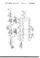
- FIG.3is a schematic diagram of a multi-channel receiver incorporating the invention.
- Each channelcomprises a transducer 12", linear amplifier 14", mixer 16" and second linear amplifier 19".
- the individual channelsare phase delayed by scan control 20" as discussed in regard to FIG. 2, added together, demodulated by detector 23" and displayed on output display 24".
- a TGC generator 18"produces the required TGC waveform and a superheterodyne generator 28" produces a heterodyne signal.
- the TGC signal and the heterodyne signalare fed as the two inputs into a mixer 30 which preferably is an analog multiplier.
- the output of multiplier 30is a heterodyne signal modulated by the TGC waveform.
- This combined TGC and heterodyne signalis fed to all the single-channel mixer 16" wherein it produces the heterodyne frequency shift as well as the gain control.
- the inventive circuitrequires N+1 multipliers where N is the number of channels.
- the prior-art circuit of FIG. 2requires 2N multipliers. The invention thus provides an important reduction in the complexity and cost of a multi-channel receiver with large number of channels.
- FIG. 4shows the waveforms of the combined TGC and heterodyne signals of FIG. 3.
- the TGC signal 32starts with a low value such as zero immediately after the transmitted pulse and rises with time at a rate determined by the parameters of the system.
- the beam intensitywill be relatively constant and the reflected intensity will be reduced mainly by the exponential attenuation with distance through the absorbing medium.
- the gain in this caseshould rise somewhat exponentially with time.
- the beam intensityis further reduced by beam spreading, so the TGC waveform should increase faster than exponentially.
- the TGC signalis fed into a first input 34 of multiplier 30.
- the superheterodyne signal 36is a continous sinusoidal wave. It is fed into a second input 38 of multiplier 30.
- the product of the two inputs coming out of output 40 of multiplier 30is the modulated sinusoid 42 having an amplitude envelope starting at a low value approaching zero at the instant of pulse generation and rising to a high value just before the following pulse. Mixing this waveform with the incoming signal in a receiver channel produces the desired combination of TGC and heterodyne frequency conversion.
Landscapes
- Engineering & Computer Science (AREA)
- Computer Networks & Wireless Communication (AREA)
- Physics & Mathematics (AREA)
- General Physics & Mathematics (AREA)
- Radar, Positioning & Navigation (AREA)
- Remote Sensing (AREA)
- Measurement Of Velocity Or Position Using Acoustic Or Ultrasonic Waves (AREA)
- Ultra Sonic Daignosis Equipment (AREA)
Abstract
Description
Claims (2)
Priority Applications (1)
| Application Number | Priority Date | Filing Date | Title |
|---|---|---|---|
| US06/353,010US4378596A (en) | 1980-07-25 | 1982-03-01 | Multi-channel sonic receiver with combined time-gain control and heterodyne inputs |
Applications Claiming Priority (2)
| Application Number | Priority Date | Filing Date | Title |
|---|---|---|---|
| US17232380A | 1980-07-25 | 1980-07-25 | |
| US06/353,010US4378596A (en) | 1980-07-25 | 1982-03-01 | Multi-channel sonic receiver with combined time-gain control and heterodyne inputs |
Related Parent Applications (1)
| Application Number | Title | Priority Date | Filing Date |
|---|---|---|---|
| US17232380AContinuation | 1980-07-25 | 1980-07-25 |
Publications (1)
| Publication Number | Publication Date |
|---|---|
| US4378596Atrue US4378596A (en) | 1983-03-29 |
Family
ID=26867963
Family Applications (1)
| Application Number | Title | Priority Date | Filing Date |
|---|---|---|---|
| US06/353,010Expired - LifetimeUS4378596A (en) | 1980-07-25 | 1982-03-01 | Multi-channel sonic receiver with combined time-gain control and heterodyne inputs |
Country Status (1)
| Country | Link |
|---|---|
| US (1) | US4378596A (en) |
Cited By (32)
| Publication number | Priority date | Publication date | Assignee | Title |
|---|---|---|---|---|
| EP0159081A1 (en)* | 1984-04-10 | 1985-10-23 | Laboratoires D'electronique Philips | Apparatus for ultrasonic echographic investigation of media |
| US4691571A (en)* | 1985-03-04 | 1987-09-08 | Dymax Corporation | Tissue signature tracking transceiver having upconverted IF amplification |
| US5030956A (en)* | 1989-04-25 | 1991-07-09 | Murphy Quentin M | Radar tomography |
| JPH03261461A (en)* | 1989-10-17 | 1991-11-21 | Us Government | Method of characterizing amplitude of pulse sequence of ultrasonic wave |
| US5859915A (en)* | 1997-04-30 | 1999-01-12 | American Technology Corporation | Lighted enhanced bullhorn |
| US5885129A (en)* | 1997-03-25 | 1999-03-23 | American Technology Corporation | Directable sound and light toy |
| US5889870A (en)* | 1996-07-17 | 1999-03-30 | American Technology Corporation | Acoustic heterodyne device and method |
| US20020126854A1 (en)* | 1997-04-30 | 2002-09-12 | American Technology Corporation | Parametric ring emitter |
| US20020191808A1 (en)* | 2001-01-22 | 2002-12-19 | American Technology Corporation | Single-ended planar-magnetic speaker |
| US20050089176A1 (en)* | 1999-10-29 | 2005-04-28 | American Technology Corporation | Parametric loudspeaker with improved phase characteristics |
| US20050100181A1 (en)* | 1998-09-24 | 2005-05-12 | Particle Measuring Systems, Inc. | Parametric transducer having an emitter film |
| US20050152561A1 (en)* | 2002-01-18 | 2005-07-14 | Spencer Michael E. | Modulator - amplifier |
| US6934402B2 (en) | 2001-01-26 | 2005-08-23 | American Technology Corporation | Planar-magnetic speakers with secondary magnetic structure |
| US20050195985A1 (en)* | 1999-10-29 | 2005-09-08 | American Technology Corporation | Focused parametric array |
| US20050240127A1 (en)* | 2004-03-02 | 2005-10-27 | Ralf Seip | Ultrasound phased arrays |
| US20060280315A1 (en)* | 2003-06-09 | 2006-12-14 | American Technology Corporation | System and method for delivering audio-visual content along a customer waiting line |
| US20070010805A1 (en)* | 2005-07-08 | 2007-01-11 | Fedewa Russell J | Method and apparatus for the treatment of tissue |
| US20070038096A1 (en)* | 2005-07-06 | 2007-02-15 | Ralf Seip | Method of optimizing an ultrasound transducer |
| US20070189548A1 (en)* | 2003-10-23 | 2007-08-16 | Croft Jams J Iii | Method of adjusting linear parameters of a parametric ultrasonic signal to reduce non-linearities in decoupled audio output waves and system including same |
| US20070219448A1 (en)* | 2004-05-06 | 2007-09-20 | Focus Surgery, Inc. | Method and Apparatus for Selective Treatment of Tissue |
| US20080039724A1 (en)* | 2006-08-10 | 2008-02-14 | Ralf Seip | Ultrasound transducer with improved imaging |
| US20080077056A1 (en)* | 2006-09-21 | 2008-03-27 | Shuhei Kagosaki | HIFU probe for treating tissue with in-line degassing of fluid |
| US20090069677A1 (en)* | 2007-09-11 | 2009-03-12 | Focus Surgery, Inc. | System and method for tissue change monitoring during hifu treatment |
| US20110201976A1 (en)* | 2005-06-01 | 2011-08-18 | Focus Surgery, Inc. | Laparoscopic hifu probe |
| US8275137B1 (en) | 2007-03-22 | 2012-09-25 | Parametric Sound Corporation | Audio distortion correction for a parametric reproduction system |
| US8767979B2 (en) | 2010-06-14 | 2014-07-01 | Parametric Sound Corporation | Parametric transducer system and related methods |
| US8903104B2 (en) | 2013-04-16 | 2014-12-02 | Turtle Beach Corporation | Video gaming system with ultrasonic speakers |
| US8934650B1 (en) | 2012-07-03 | 2015-01-13 | Turtle Beach Corporation | Low profile parametric transducers and related methods |
| US8958580B2 (en) | 2012-04-18 | 2015-02-17 | Turtle Beach Corporation | Parametric transducers and related methods |
| US8988911B2 (en) | 2013-06-13 | 2015-03-24 | Turtle Beach Corporation | Self-bias emitter circuit |
| US9036831B2 (en) | 2012-01-10 | 2015-05-19 | Turtle Beach Corporation | Amplification system, carrier tracking systems and related methods for use in parametric sound systems |
| US9332344B2 (en) | 2013-06-13 | 2016-05-03 | Turtle Beach Corporation | Self-bias emitter circuit |
Citations (3)
| Publication number | Priority date | Publication date | Assignee | Title |
|---|---|---|---|---|
| US2798949A (en)* | 1954-06-11 | 1957-07-09 | Scholz Paul | Sensitivity time control circuit |
| US2984741A (en)* | 1960-08-08 | 1961-05-16 | Bronstein Jacob | Sensitivity time control system |
| US3987403A (en)* | 1974-01-18 | 1976-10-19 | Russell Peter Smith | Sensory aids for the blind |
- 1982
- 1982-03-01USUS06/353,010patent/US4378596A/ennot_activeExpired - Lifetime
Patent Citations (3)
| Publication number | Priority date | Publication date | Assignee | Title |
|---|---|---|---|---|
| US2798949A (en)* | 1954-06-11 | 1957-07-09 | Scholz Paul | Sensitivity time control circuit |
| US2984741A (en)* | 1960-08-08 | 1961-05-16 | Bronstein Jacob | Sensitivity time control system |
| US3987403A (en)* | 1974-01-18 | 1976-10-19 | Russell Peter Smith | Sensory aids for the blind |
Cited By (55)
| Publication number | Priority date | Publication date | Assignee | Title |
|---|---|---|---|---|
| FR2563918A1 (en)* | 1984-04-10 | 1985-11-08 | Labo Electronique Physique | MEDIUM EXPLORATION APPARATUS BY ULTRASOUND ULTRASONOGRAPHY |
| EP0159081A1 (en)* | 1984-04-10 | 1985-10-23 | Laboratoires D'electronique Philips | Apparatus for ultrasonic echographic investigation of media |
| US4691571A (en)* | 1985-03-04 | 1987-09-08 | Dymax Corporation | Tissue signature tracking transceiver having upconverted IF amplification |
| US5030956A (en)* | 1989-04-25 | 1991-07-09 | Murphy Quentin M | Radar tomography |
| JPH03261461A (en)* | 1989-10-17 | 1991-11-21 | Us Government | Method of characterizing amplitude of pulse sequence of ultrasonic wave |
| EP0424245A3 (en)* | 1989-10-17 | 1991-12-11 | United States Government, As Represented By The National Aeronautics And Space Administration | Method and apparatus for characterizing reflected ultrasonic pulses |
| US5889870A (en)* | 1996-07-17 | 1999-03-30 | American Technology Corporation | Acoustic heterodyne device and method |
| US5885129A (en)* | 1997-03-25 | 1999-03-23 | American Technology Corporation | Directable sound and light toy |
| US5859915A (en)* | 1997-04-30 | 1999-01-12 | American Technology Corporation | Lighted enhanced bullhorn |
| US20020126854A1 (en)* | 1997-04-30 | 2002-09-12 | American Technology Corporation | Parametric ring emitter |
| US7088830B2 (en) | 1997-04-30 | 2006-08-08 | American Technology Corporation | Parametric ring emitter |
| US20050100181A1 (en)* | 1998-09-24 | 2005-05-12 | Particle Measuring Systems, Inc. | Parametric transducer having an emitter film |
| US20050195985A1 (en)* | 1999-10-29 | 2005-09-08 | American Technology Corporation | Focused parametric array |
| US8199931B1 (en) | 1999-10-29 | 2012-06-12 | American Technology Corporation | Parametric loudspeaker with improved phase characteristics |
| US20050089176A1 (en)* | 1999-10-29 | 2005-04-28 | American Technology Corporation | Parametric loudspeaker with improved phase characteristics |
| US20020191808A1 (en)* | 2001-01-22 | 2002-12-19 | American Technology Corporation | Single-ended planar-magnetic speaker |
| US20070127767A1 (en)* | 2001-01-22 | 2007-06-07 | American Technology Corporation | Single-ended planar-magnetic speaker |
| US7142688B2 (en) | 2001-01-22 | 2006-11-28 | American Technology Corporation | Single-ended planar-magnetic speaker |
| US6934402B2 (en) | 2001-01-26 | 2005-08-23 | American Technology Corporation | Planar-magnetic speakers with secondary magnetic structure |
| US20090097693A1 (en)* | 2001-01-26 | 2009-04-16 | Croft Iii James J | Planar-magnetic speakers with secondary magnetic structure |
| US20060050923A1 (en)* | 2001-01-26 | 2006-03-09 | American Technology Corporation | Planar-magnetic speakers with secondary magnetic structure |
| US7224219B2 (en) | 2002-01-18 | 2007-05-29 | American Technology Corporation | Modulator-amplifier |
| US20050152561A1 (en)* | 2002-01-18 | 2005-07-14 | Spencer Michael E. | Modulator - amplifier |
| US20070015473A1 (en)* | 2002-01-18 | 2007-01-18 | American Technology Corporation | Modulator-amplifier |
| US7109789B2 (en) | 2002-01-18 | 2006-09-19 | American Technology Corporation | Modulator—amplifier |
| US20060280315A1 (en)* | 2003-06-09 | 2006-12-14 | American Technology Corporation | System and method for delivering audio-visual content along a customer waiting line |
| US7564981B2 (en) | 2003-10-23 | 2009-07-21 | American Technology Corporation | Method of adjusting linear parameters of a parametric ultrasonic signal to reduce non-linearities in decoupled audio output waves and system including same |
| US20070189548A1 (en)* | 2003-10-23 | 2007-08-16 | Croft Jams J Iii | Method of adjusting linear parameters of a parametric ultrasonic signal to reduce non-linearities in decoupled audio output waves and system including same |
| US20050240127A1 (en)* | 2004-03-02 | 2005-10-27 | Ralf Seip | Ultrasound phased arrays |
| US20100022921A1 (en)* | 2004-03-02 | 2010-01-28 | Ralf Seip | Ultrasound phased arrays |
| US7662114B2 (en) | 2004-03-02 | 2010-02-16 | Focus Surgery, Inc. | Ultrasound phased arrays |
| US20070219448A1 (en)* | 2004-05-06 | 2007-09-20 | Focus Surgery, Inc. | Method and Apparatus for Selective Treatment of Tissue |
| US20110201976A1 (en)* | 2005-06-01 | 2011-08-18 | Focus Surgery, Inc. | Laparoscopic hifu probe |
| US8038631B1 (en) | 2005-06-01 | 2011-10-18 | Sanghvi Narendra T | Laparoscopic HIFU probe |
| US20070038096A1 (en)* | 2005-07-06 | 2007-02-15 | Ralf Seip | Method of optimizing an ultrasound transducer |
| US20070010805A1 (en)* | 2005-07-08 | 2007-01-11 | Fedewa Russell J | Method and apparatus for the treatment of tissue |
| US20080091123A1 (en)* | 2005-07-08 | 2008-04-17 | Focus Surgery, Inc. | Method and apparatus for treatment of tissue |
| US20080091124A1 (en)* | 2005-07-08 | 2008-04-17 | Focus Surgery, Inc. | Method and apparatus for treatment of tissue |
| US10293188B2 (en) | 2005-07-08 | 2019-05-21 | Focus Surgery, Inc. | Method and apparatus for the treatment of tissue |
| US9095695B2 (en) | 2005-07-08 | 2015-08-04 | Focus Surgery, Inc. | Method and apparatus for treatment of tissue |
| US20080039724A1 (en)* | 2006-08-10 | 2008-02-14 | Ralf Seip | Ultrasound transducer with improved imaging |
| US20080077056A1 (en)* | 2006-09-21 | 2008-03-27 | Shuhei Kagosaki | HIFU probe for treating tissue with in-line degassing of fluid |
| US7559905B2 (en) | 2006-09-21 | 2009-07-14 | Focus Surgery, Inc. | HIFU probe for treating tissue with in-line degassing of fluid |
| US8275137B1 (en) | 2007-03-22 | 2012-09-25 | Parametric Sound Corporation | Audio distortion correction for a parametric reproduction system |
| US20090069677A1 (en)* | 2007-09-11 | 2009-03-12 | Focus Surgery, Inc. | System and method for tissue change monitoring during hifu treatment |
| US8235902B2 (en) | 2007-09-11 | 2012-08-07 | Focus Surgery, Inc. | System and method for tissue change monitoring during HIFU treatment |
| US9002032B2 (en) | 2010-06-14 | 2015-04-07 | Turtle Beach Corporation | Parametric signal processing systems and methods |
| US8767979B2 (en) | 2010-06-14 | 2014-07-01 | Parametric Sound Corporation | Parametric transducer system and related methods |
| US8903116B2 (en) | 2010-06-14 | 2014-12-02 | Turtle Beach Corporation | Parametric transducers and related methods |
| US9036831B2 (en) | 2012-01-10 | 2015-05-19 | Turtle Beach Corporation | Amplification system, carrier tracking systems and related methods for use in parametric sound systems |
| US8958580B2 (en) | 2012-04-18 | 2015-02-17 | Turtle Beach Corporation | Parametric transducers and related methods |
| US8934650B1 (en) | 2012-07-03 | 2015-01-13 | Turtle Beach Corporation | Low profile parametric transducers and related methods |
| US8903104B2 (en) | 2013-04-16 | 2014-12-02 | Turtle Beach Corporation | Video gaming system with ultrasonic speakers |
| US8988911B2 (en) | 2013-06-13 | 2015-03-24 | Turtle Beach Corporation | Self-bias emitter circuit |
| US9332344B2 (en) | 2013-06-13 | 2016-05-03 | Turtle Beach Corporation | Self-bias emitter circuit |
Similar Documents
| Publication | Publication Date | Title |
|---|---|---|
| US4378596A (en) | Multi-channel sonic receiver with combined time-gain control and heterodyne inputs | |
| US4005382A (en) | Signal processor for ultrasonic imaging | |
| US3950723A (en) | Sonar apparatus | |
| CA1129539A (en) | Ultrasonic imaging system utilizing dynamic and pseudo-dynamic focusing | |
| KR0138901B1 (en) | Ultrasonic process and circuits | |
| KR100749973B1 (en) | Prf adjustment method and apparatus, and ultrasonic wave imaging apparatus | |
| US4208916A (en) | Electronic ultrasonic sector scanning apparatus and method | |
| US5419330A (en) | Ultrasonic diagnostic equipment | |
| US4198702A (en) | Time varying gain amplifier for side scan sonar applications | |
| NL8320312A (en) | ULTRASONIC IMAGING SYSTEM WITH CORRECTION FOR SPEED INHOMOGNICITY AND MULTI-WAY INTERFERENCE USING AN ULTRASONIC IMAGE ARRAY. | |
| GB1418614A (en) | Scanning sonar system | |
| EP0146073A2 (en) | Ultrasonic diagnosing apparatus | |
| US5417217A (en) | Echo beam former for an ultrasonic diagnostic apparatus | |
| US4679565A (en) | Ultrasonic diagnostic apparatus using non-linear parameters of an organ | |
| US4204281A (en) | Signal processing system for underwater transducer | |
| US5476098A (en) | Partially coherent imaging for large-aperture phased arrays | |
| US5548561A (en) | Ultrasound image enhancement using beam-nulling | |
| US5090412A (en) | Ultrasonic diagnosis apparatus | |
| US20020009204A1 (en) | Signal processing method and apparatus and imaging system | |
| US5050611A (en) | Ultrasonic imaging apparatus | |
| JPH06114056A (en) | Ultrasonic diagnostic equipment | |
| US4576046A (en) | Device for the examination of objects by means of ultrasound echography | |
| JPH02218353A (en) | Ultrasonic wave diagnosing device | |
| JP2868869B2 (en) | FM-CW fish finder | |
| SU871058A1 (en) | Device for measuring ultrasonic wave attenuation |
Legal Events
| Date | Code | Title | Description |
|---|---|---|---|
| STCF | Information on status: patent grant | Free format text:PATENTED CASE | |
| FEPP | Fee payment procedure | Free format text:PAYOR NUMBER ASSIGNED (ORIGINAL EVENT CODE: ASPN); ENTITY STATUS OF PATENT OWNER: LARGE ENTITY | |
| MAFP | Maintenance fee payment | Free format text:PAYMENT OF MAINTENANCE FEE, 4TH YEAR, PL 96-517 (ORIGINAL EVENT CODE: M170); ENTITY STATUS OF PATENT OWNER: LARGE ENTITY Year of fee payment:4 | |
| AS | Assignment | Owner name:DIASONICS, INC., A CORP. OF CA Free format text:MERGER;ASSIGNOR:DIASONICS CARDIO/IMAGING INC.;REEL/FRAME:005319/0106 Effective date:19821230 | |
| AS | Assignment | Owner name:DIASONICS DELAWARE, INC., A CORP. OF DE Free format text:MERGER;ASSIGNOR:DIASONICS, INC.;REEL/FRAME:005319/0459 Effective date:19880520 | |
| MAFP | Maintenance fee payment | Free format text:PAYMENT OF MAINTENANCE FEE, 8TH YEAR, PL 96-517 (ORIGINAL EVENT CODE: M171); ENTITY STATUS OF PATENT OWNER: LARGE ENTITY Year of fee payment:8 | |
| AS | Assignment | Owner name:DIASONICS INC., CALIFORNIA Free format text:CHANGE OF NAME;ASSIGNOR:DIASONICS DELAWARE INC.;REEL/FRAME:006364/0019 Effective date:19880516 | |
| MAFP | Maintenance fee payment | Free format text:PAYMENT OF MAINTENANCE FEE, 12TH YEAR, LARGE ENTITY (ORIGINAL EVENT CODE: M185); ENTITY STATUS OF PATENT OWNER: LARGE ENTITY Year of fee payment:12 |