US4377168A - Cryosurgical instrument - Google Patents
Cryosurgical instrumentDownload PDFInfo
- Publication number
- US4377168A US4377168AUS06/236,521US23652181AUS4377168AUS 4377168 AUS4377168 AUS 4377168AUS 23652181 AUS23652181 AUS 23652181AUS 4377168 AUS4377168 AUS 4377168A
- Authority
- US
- United States
- Prior art keywords
- gas
- valve
- cavity
- conduit
- tip
- Prior art date
- Legal status (The legal status is an assumption and is not a legal conclusion. Google has not performed a legal analysis and makes no representation as to the accuracy of the status listed.)
- Expired - Lifetime
Links
Images


Classifications
- F—MECHANICAL ENGINEERING; LIGHTING; HEATING; WEAPONS; BLASTING
- F25—REFRIGERATION OR COOLING; COMBINED HEATING AND REFRIGERATION SYSTEMS; HEAT PUMP SYSTEMS; MANUFACTURE OR STORAGE OF ICE; LIQUEFACTION SOLIDIFICATION OF GASES
- F25B—REFRIGERATION MACHINES, PLANTS OR SYSTEMS; COMBINED HEATING AND REFRIGERATION SYSTEMS; HEAT PUMP SYSTEMS
- F25B9/00—Compression machines, plants or systems, in which the refrigerant is air or other gas of low boiling point
- F25B9/02—Compression machines, plants or systems, in which the refrigerant is air or other gas of low boiling point using Joule-Thompson effect; using vortex effect
- A—HUMAN NECESSITIES
- A61—MEDICAL OR VETERINARY SCIENCE; HYGIENE
- A61B—DIAGNOSIS; SURGERY; IDENTIFICATION
- A61B18/00—Surgical instruments, devices or methods for transferring non-mechanical forms of energy to or from the body
- A61B18/02—Surgical instruments, devices or methods for transferring non-mechanical forms of energy to or from the body by cooling, e.g. cryogenic techniques
- A—HUMAN NECESSITIES
- A61—MEDICAL OR VETERINARY SCIENCE; HYGIENE
- A61B—DIAGNOSIS; SURGERY; IDENTIFICATION
- A61B17/00—Surgical instruments, devices or methods
- A61B2017/00367—Details of actuation of instruments, e.g. relations between pushing buttons, or the like, and activation of the tool, working tip, or the like
- A61B2017/00371—Multiple actuation, e.g. pushing of two buttons, or two working tips becoming operational
- A—HUMAN NECESSITIES
- A61—MEDICAL OR VETERINARY SCIENCE; HYGIENE
- A61B—DIAGNOSIS; SURGERY; IDENTIFICATION
- A61B18/00—Surgical instruments, devices or methods for transferring non-mechanical forms of energy to or from the body
- A61B2018/00005—Cooling or heating of the probe or tissue immediately surrounding the probe
- A61B2018/00041—Heating, e.g. defrosting
- F—MECHANICAL ENGINEERING; LIGHTING; HEATING; WEAPONS; BLASTING
- F25—REFRIGERATION OR COOLING; COMBINED HEATING AND REFRIGERATION SYSTEMS; HEAT PUMP SYSTEMS; MANUFACTURE OR STORAGE OF ICE; LIQUEFACTION SOLIDIFICATION OF GASES
- F25B—REFRIGERATION MACHINES, PLANTS OR SYSTEMS; COMBINED HEATING AND REFRIGERATION SYSTEMS; HEAT PUMP SYSTEMS
- F25B2309/00—Gas cycle refrigeration machines
- F25B2309/02—Gas cycle refrigeration machines using the Joule-Thompson effect
- F25B2309/021—Gas cycle refrigeration machines using the Joule-Thompson effect with a cryosurgical probe tip having a specific construction
Definitions
- This inventionrelates to cryosurgical instruments in which a hollow probe tip is cooled by the passage of a fluid refrigerant through the hollow interior of the tip.
- the inventionis concerned with instruments cooled by the Joule-Thomson effect or isenthalpic expansion of a gaseous refrigerant through a flow restriction adjacent the hollow interior or cavity of the tip.
- coolingis the result of the refrigerant fluid suffering a drop of pressure caused by the flow restriction through which the fluid passes.
- the restriction and consequently the coolingtakes place within the instrument itself, and therefore the refrigerant reaches the tip of the instrument from the source at, or substantially at, the source pressure and temperature and the cooling occurs in the immediate vicinity of the tip.
- the refrigerantoccupies the tip cavity of the instrument as a cold gaseous fluid cooled by isenthalpic gaseous expansion and takes up its latent heat of vaporization from the wall of the tip cavity and therefore from the tissue with which the probe is contacted.
- the cold gaseous fluidmay carry with it some proportion of liquid refrigerant in the form of droplets or mist.
- cryosurgical instrumentit is usually important that such a cryosurgical instrument be quickly and precisely controlled in the cooling, refrigeration, or "freezing" phase; while it is of comparable importance to control warming, defrosting, (or “thawing") of the instrument, particularly because it is desirable that it can quickly be released from the congelation with the tissue which it effects.
- Such warminginvolves a release or supply of heat, such as to raise the temperature of the probe and thereby the tissue and whatever other material constitutes their interface, such as saline solution deliberately used at such interface.
- cryosurgical instrumente.g., disclosed in detail in U.S. Pat. No. 3,548,829 to Reynolds et al, U.S. Pat. No. 3,451,395 to Thyberg, and U.S. Pat. Nos. 3,393,679; 3,512,531 and 3,613,689 to Crump et al
- the cooling of the hollow working tip of the instrumentis provided by unseating a flow valve element in the return line located downstream from the tip and simultaneously forming a restrictive orifice at the inlet to the tip by contacting an orifice seat with a moveable conduit.
- Refrigerant liquid or gasthen flows from a source through the orifice and exhausts through the unseated downstream valve to effect cooling of the tip by evaporation or by a Joule-Thomson expansion. Warming of the tip is accomplished by seating the downstream valve element and simultaneously separating the moveable conduit from the orifice seat, thus permitting refrigerant at ambient temperature to flood the hollow working tip.
- This instrument typerequires a moveable conduit and valving that are complex and therefore difficult and expensive to make on a consistently reliable basis.
- Wallachsuggested warming by blocking the exhaust flow from the probe by closing a valve. Gas from the source, being rapidly increased in pressure would condense in the probe by reason of giving up latent heat, warming the probe. Wallach specifically proposed a cryosurgical instrument cooled by the Joule-Thomson effect, and warmed by blocking off the exhaust so that there would be a quick rise of pressure within the probe.
- the pressure of the supplied gasbuilds up within the probe until it balances the source pressure, the rate of flow of the gas entering the tip cavity of the probe by its ordinary path (i.e., through the refrigerating restriction) decreasing as the pressure difference between the pressure source and the cavity sink (i.e., the probe cavity and its immediately adjacent passage volumes) diminishes; likewise the rate of flow from the source to the sink, which is subject to the control exercised by the restriction, similarly decreases.
- leakagee.g., past the exhaust valve, if of a similar order to passage through the refrigerating restriction, may result in failure to pressurize the cavity adequately and consequent inadequacy of warming.
- Such constructionsinvolve a provision in a Joule-Thomson type of instrument of a line of connection in which there is no deliberately provided restriction (but the volume, rate of flow of the gas is controlled or restricted in the freeze mode to undergo the Joule-Thomson expansion) between a source of pressurized gas and the cavity of a cryosurgical probe, so that the operator can operate valve means so as to admit warming gas at substantially ambient temperature at a high rate, into the cavity, usually through the unrestricted exhaust conduit or line (hence, the nomenclature "reverse-flow”), where such gas performs the required warming.
- the gasperforms the warming largely or partially by condensing within the probe, the condensate then being allowed to escape as a liquid, or partly as a liquid and partly as a gas, being purged to atmosphere by following or entraining gas, the probe temperature having been raised by the latent heat. Liquid condensate remaining within the probe may be purged by venting or subsequently to warming, during the early part of the next cooling mode.
- the valving to effect changing from the freeze to the defrost modeare provided on the exhaust side of the instrument. If the valving were located on the inlet side rather than the exhaust side, it would provide an unrestricted exhaust flow in the instrument resulting in better efficiency; a more maintenance-free instrument, since the valve would not encounter cryogenic temperatures; and a safer instrument since no high pressure gas condition would exist in the instrument in the static condition.
- U.S. Pat. No. 3,933,156 to Riggsdiscloses insulating outer tubes surrounding concentric expansion tubes (i.e., an inlet and an exhaust tube) to minimize heat transfer between the tubes and condensation of refrigerant in the line of the process.
- U.S. Pat. No. 4,015,606 Mitchinerdiscloses a cryosurgical instrument having a construction for controlling the freeze zone in the tip by moving the exhaust tube conduit in the tip towards or away from the supply (inlet) tube conduit.
- the present inventionrelates to a cryosurgical instrument of the kind in which there is a probe having a tip or applicator with a wall of thermally conductive material enclosing a cavity.
- a supply of refrigerant fluidhas its rate of flow controlled by passing it through a first duct having a flow restriction, expanding it with Joule-Thomson cooling in the tip, and permitting the resultant gas to escape through an exhaust duct.
- a warming fluidis supplied into the cavity under pressure through a second duct while at substantially ambient temperature or at a temperature high relative to the probe temperature achieved in the cooling mode.
- the cooling or freeze modeis activated by a trigger valve upstream from the probe tip.
- Trigger movementallows the flow of source cryogen gas, e.g., carbon dioxide or nitrous oxide, past a valve seat into a delivery tube or first duct which meters the volume of gas flowing through it so as to provide a correct pressure differential as it flows into the expansion cavity of the tip allowing an efficient Joule-Thomson or isoentropic expansion of the gas to occur.
- the spent gasflows out of the cavity into the annulus or space between the outside diameter of a defrost tube and the inside diameter of an exhaust tube.
- the spent or cold gasthen flows into a pulse valve housing downstream from the tip.
- the pressure of the spent gasis insufficient to depress a spring that normally holds the pulse valve open, so the spent gas can flow around the pulse valve into an exhaust hose and out to atmosphere through an exhaust port.
- the freeze triggeris released and an adjacent defrost trigger upstream from the probe tip is depressed.
- Trigger movementallows the flow of the source cryogen gas past a valve seat into a defrost tube or second duct which meters the volume of gas to several magnitudes the volume that flows through the delivery tube or first duct.
- the warm, unexpanded gasflows into the expansion area in the tip and then into the exhaust tube and into the pulse valve housing. While in the tip, the warm gas condenses, giving up its latent heat to the surrounding tip to defrost the same.
- the pressure and volume of this gasis sufficient to depress the spring and close the pulse valve allowing the gas to flow only through drilled or bleed holes in the pulse valve.
- the gas flow through the bleedis of a higher magnitude than the gas flow during the freeze mode when the pulse valve is open, sufficient back pressure occurs because of the location and size of the bleed holes in the pulse valve so that defrost action takes place due to the warm defrost gas continuously flowing past the expansion chamber at sufficient back pressure, i.e., an unobstructed exhaust is provided to continuously purge a higher volume flow of warm gas in the defrost mode.
- the valving to effect changing from the freeze to the defrost mode and vice-versaare located on the inlet side of the probe of the instrument, there is a continuous exhaust flow in both the freeze and defrost mode resulting in better efficiency as noted above, i.e., quicker freeze and defrost and the precluding of condensation in the exhaust tube; a more maintenance-free instrument since the trigger valves do not encounter cryogenic temperatures; and a safer instrument since no high pressure gas condition exists in the instrument in a static condition, the exhaust flow being continuous until depleted into the atmosphere.
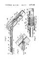
- FIG. 1is a top plan view of the cryosurgical instrument of the present invention
- FIG. 2is a side view in elevation of the cryosurgical instrument illustrated in FIG. 1;
- FIG. 3is a cross sectional view of the tip of the instrument illustrated in FIG. 2 taken substantially along the plane indicated by line 3--3;
- FIG. 4is a cross sectional view of an alternate form of tip which can be used with the cryosurgical instrument of FIGS. 1 and 2;
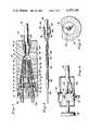
- FIG. 5is a longitudinal cross sectional view of the cryosurgical instrument illustrated in FIG. 2;
- FIG. 6is a cross sectional view taken substantially along the plane indicated by line 6--6 of FIG. 5;
- FIG. 7is a cross sectional view taken substantially along the plane indicated by line 7--7 of FIG. 5;
- FIG. 8is a cross sectional view taken substantially along the plane indicated by line 8--8 of FIG. 5;
- FIG. 9is a cross sectional view taken substantially along the plane indicated by line 9--9 of FIG. 5;
- FIG. 10is a cross sectional view taken substantially along the plane indicated by line 10--10 of FIG. 2;
- FIG. 11is a cross sectional view taken substantially along the plane indicated by line 11--11 of FIG. 3;
- FIG. 12is a longitudinal cross-sectional view of an alternate embodiment of a cryosurgical instrument of the present invention.
- FIG. 13is a cross-sectional view taken substantially along the plane indicated by line 13--13 of FIG. 12;
- FIG. 14is a schematic diagram of a valve console for use with the instrument of FIGS. 12 and 13.
- the cryosurgical instrument 10 of the present inventionincludes a steel or plastic outer housing 12 having a pair of indentations 14 and 16 into which the fingers of the user's hand can be placed to grip the housing 12.
- a tube 18Extending outwardly from one end of the housing is a tube 18 having a hollow tip 20 threadedly connected at one end thereto and provided with a cavity 22.
- the tip 20is made from a heat conductive metal and is adapted to contact tissue to be treated using the instrument 10.
- the tube 18is fixed by welding, brazing, swaging or the like, to the hollow housing 12.
- Opening of the valve on the gas tank or cylinderadmits gas into the pressure gauge assembly 26, registering the pressure on the gage dial 40 and admits gas into the inlet tube 30.
- the inlet tubeis connected to an inlet valve assembly 42.
- Inlet valve assembly 42includes a ferrule 44 slidably received in one end of a block 46. Ferrule 44 is received within a bore 48 having an annular shoulder 50. A nut 52 is threadedly received behind the ferrule 44 in bore 48. Nut 52 also receives the inlet tube 30 therethrough. Upon threading of nut 52 into bore 48, the forward end of the ferrule contacts annular shoulder 50 which causes the ferrule to clamp about the end of inlet tube 30 received therethrough.
- Valve construction 60includes a hollow body member 62 threadedly received in each of the branch ports 56 and 58.
- a reciprocable plunger 64extends through the hollow body member 62 and terminates in a cap 66 adapted to seat on one end of the hollow body member 62 and is movable towards and away from the same.
- the opposite end 67 of the plunger 64extends through a continuation of branch port 56 and 58, through a seal 68 cooperating with an O-ring 70, a guide member 72 threadedly received in the upper end of each of the branch ports 56 and 58 and is in contact with a rotatable trigger 74A or 74B.
- the triggers 74A and 74Bare each rotatably mounted on a pin 76 extending through the housing 12 in front of the valve block 46. Upon rotations of either of the triggers 74A or 74B, a rear surface of the trigger will contact the adjacent end 67 of plunger 64 and move it rearwardly through the corresponding branch port 56 or 58 unseating cap 66 from the hollow interior of its corresponding valve body 62, enabling gas to be conducted from orifice 54 into the interior of the valve body 62 and then through either a port A or a port B between the valve body 62 and the seal 68.
- the cap 66can be reseated upon the end of valve body 62 by a buildup of inlet gas behind the cap 66 and orifice 54 after release of the trigger 74A or 74B.
- a return springcan encircle the plunger 64 between an enlarged portion of its diameter and the cap 66 to effect a return force upon elongation of the spring upon depression of the trigger 74A or 74B.
- trigger 74Ais depressed to admit gas through port A, while trigger 74B is depressed in the defrost mode to admit gas through port B.
- ports A and Bare in communication with the ends of a delivery conduit 80 and a defrost conduit 82, respectively.
- Each of the delivery and defrost conduits 80 and 82, respectively,extend through a tube retainer 84 threadedly received in spaced portions of inlet valve block 42.
- An O-ring seal 86is placed between one end of the retainer 84 and the tube or conduit 80 or 82.
- the delivery tube 80has a reduced diameter portion 88 which extends through a union 90 into the interior of a coaxial defrost conduit 92 also joined to union 90 and in communication with the end of the defrost delivery tube 82.
- the defrost tube 92 with its coaxial inlet delivery tube 88extends into an insulator sleeve 94.
- the insulator sleeve 94is press fit within one end of the outer sheath 18 and has a shoulder 96 in abutment with an annular reduced diameter portion of the sheath 18.
- the tip assembly 104Threadedly received on the forward end of insulator sleeve 94 is the tip assembly 104.
- the tip assembly 104includes the thermoconductive tip 20 having a cavity 22, brazed to an outer insulator sleeve 106.
- Sleeve 106has an internal portion threadedly received upon the threaded end 95 of insulator sleeve 94.
- the tip 20' illustrated in FIG. 4is of substantially identical construction as that illustrated in FIG. 3, corresponding elements being indicated by corresponding numerals, except for the configuration thereof.
- the tip illustrated in FIG. 4is used to necrose gynecological tissue while the tip illustrated in FIG. 3 is primarily for dermatology use to freeze small lesions. In either case, the coaxial defrost and inlet delivery tubes 88 and 92 are received through the sleeve 106 into the cavity 22 adjacent the outer wall of the tip 20 or 20'.
- the exhaust pulse valve assembly 102includes a housing 108 having a bore 110 formed therethrough.
- Bore 110includes a reduced diameter continuation portion 112 formed in a plug 114 threadedly received in one end of housing 108.
- An O-ring seal 116is received in a groove 118 formed in plug 114 adjacent its threaded connection to the housing 102. Press fitted within reduced diameter bore 112 and in communication therewith and enlarged bore 110 of housing 108 in exhaust conduit 100.
- housing 108is press fitted and received within the end of exhaust tube 28, which is connected via the pressure gauge block 32 to the exhaust port 34.
- a tank of cryogenic fluidsuch as nitrous oxide or carbon dioxide is connected to the gas cylinder attachment 36.
- gasis admitted under pressure through the pressure gauge assembly 26, registering the pressure on the gauge dial 40 and admitting gas to the inlet tube 30.
- the cryogenic gasis detained at the inlet side of the inlet valve assembly 42 in orifice 54.
- the trigger 74AIn order to place the cryogenic instrument 10 in its freeze mode or condition, the trigger 74A is depressed, causing it to move to the rear of opening 75 and housing 12 about pin 76. Rotation of the trigger 74A about pin 76 causes it to contact end 67 of plunger 64 in branch conduit 58, causing it to move to the right or rear of the housing as viewed in FIGS. 5 and 7. This causes cap 66 on the end of plunger 64 to move to the right away from its seat with valve body 62 (first valve), admitting cryogenic gas from orifice 54 into the valve body 62, and through port A into the interior of the inlet delivery tube 80 and reduced diameter delivery tube 88 in coaxial relation with defrost tube 92.
- the gasegresses from the end of tube 88, which meters the volume of gas flowing through it so as to provide the correct pressure differential as it flows into tip cavity 22 allowing an efficient Joule-Thomson effect to occur or an isoentropic expansion, cooling the thermoconductive tip 20.
- the expanded or spent gasflows out of the cavity 22 into the interior of sleeve 106, through the bore in insulator sleeve 94 into the interior of exhaust tube 100. Spent or expanded gas then flows into the pulse valve housing 108.
- the trigger 74Bis depressed.
- the trigger 74Bis likewise retained on pin 76 and rotates so that a rear portion thereof strikes the end 67 of plunger 64 which is moved towards the rear of valve block 42 moving the plunger 64 within the port branch 56 to the rear of the valve block 42 as illustrated in FIG. 7.
- Thismoves cap 66 away from the end of hollow valve body 62 in the branch port 56, and enables pressurized gas in orifice 54 to flow through the interior of valve body 62, through port B, defrost delivery tube 82, union 90, defrost conduit 92, and into the interior cavity 22 of tip 20 or interior cavity 22' of tip 20'.
- the larger defrost tube 92meters the volume of gas to several times the magnitude of the volume that flows through the delivery tube 88 wherein the gas does not undergo a Joule-Thomson experiment, but remains warm and floods the cavity 22 of tip 22 or cavity 22' of tip 20'.
- the gasflows from the tip 22 into the exhaust conduit 100 into the enlarged bore 110 of the pulse valve housing 108.
- the pressure and volume of the unexpanded gasis sufficient to depress coil spring 120 and floating piston 122 to cause it to seat against an annular shoulder 136 in housing 108, allowing the gas to only flow through the bleed ports 124 and 126 into the interior bore 128, bore 130 and into the interior of the exhaust conduit 28 to be bled out the exhaust port 34.
- any manual valvesuch as a foot-operated valve, may be utilized.
- an ophthalmic-type cryosurgical probe 200illustrated in FIGS. 12 and 13 may be connected to and operated by a foot-operated switch valve 202, through a console 204, schematically depicted in FIG. 14.
- a suitable connectorallows connecting the console 204 to a cylinder 206 of cryogen (N 2 O or CO 2 ). Opening master valve of the cylinder 206 allows the gas to enter a high pressure regulator 208 which can be adjusted from 540 psi to 620 psi, providing a consistent pressure for repeatable performance.
- the gasis conveyed to an on-off valve 210 from regulator 208. When the on-off valve is in the ⁇ off ⁇ position all downstream gas is vented to atmosphere at 212. Turning the on-off valve 218 ⁇ on ⁇ allows gas to flow through two routes. The first route is to a low pressure regulator 220 through a line 222 that drops the pressure to 100 psi.
- This 100 psi gasflows through a line 224 to normally closed, manually operated 3-way footswitch valve 202, in which the downstream gas is vented to the atmosphere through port 226 in its normally closed position.
- the 100 psi gasalso flows through line 225 to a console to probe port block 228 which connects the 100 psi gas to the delivery tube 230 of the probe 200.
- This 100 psi gasis used to purge moisture from the probe. This purge is constant and continuous. High pressure feedback to low pressure regulator 220 and footswitch valve 202 is restricted by a shuttle valve 232 in the line 225.
- the pedal 234 of footswitch valve 202is depressed to achieve the freeze mode. This allows 100 psi gas to flow through the footswitch valve 202 and line 235 to the pilot actuator 236 of the normally closed valve 218 allowing high pressure gas in line 214 to flow through the valve 218 and line 238 to the delivery tube 240 of the console to probe port block 228 allowing refrigerant to enter delivery chamber 242 of probe 200 past restrictor 244 expanding in the expansion area 246, thus cooling the tip 248.
- the spent gasflows through the inner tube 250 of the probe 200 around the pulse piston 252, which is held open by a spring 254 that exerts more pressure than that of the spent gas.
- the footswitch pedal 234is released. This causes the valve in the footswitch to close and immediately vent the gas that is actuating the pilot actuator 266 of the normally open valve 264 through vent 226. Therefore, normally open valve 264 opens and allows high pressure gas to flow through it from line 262 to the defrost tube port 268 of the console to probe port block 228 through line 270 and on to the defrost tube 272 of the probe 200. This gas entering the probe is of several magnitudes higher than the gas that is used for freezing.
- This defrost gasis sufficient in pressure and volume to depress the spring 254 holding the pulse piston 252 in the open position thus closing the pulse piston by causing it to seat against annular shoulder 274 allowing gas to flow only through a drilled passageway 276 through the center of pulse piston 252.
- the flow through the passageway 276is higher than the flow around the pulse piston 252 when in the freeze mode, sufficient back pressure occurs causing high pressure gas to enter tube 250 and the hollow interior of tip 248, defrosting the tip.
- gasis trapped in a delay volume chamber 278, received during the freeze mode and held therein by a check valve 280, being depleted through a metered orifice 282 venting chamber 278.
- the pilot actuator 236 of the normally closed valve 218releases, thus closing the normally closed valve, shutting off the supply of high pressure gas to the normally closed valve 218 through port 260.
- the delivery tube 230, defrost tube 272, pulse valve assembly, inner tube 250 and exhaust tube 256may all be housed within a sheath or housing 284.
- Delivery tube 230terminates in a block 286 housing delivery chamber 242 which is in communication with a bore 288 concentrically receiving inner tube 250 therethrough.
- Block 286also has a tip support tube 290 connected to the forward end thereof in concentric relation to inlet tube 250. Tip support tube 290 is brazed or otherwise connected at 292 to tip 248.
- the forward end of tip support tube 290provides the expansion area 246, while the forward end of inner tube 250 is flared at 244 to provide an annular, metered, Joule-Thomson restriction 294.
- High pressure gascan thus flow in the freeze mode of the instrument through delivery tube 230 into delivery chamber 242, through bore 288 in block 286 in concentric relation to inner tube 250 and expand through annular restriction 294 into expansion area 246 to cool tip 248.
- the spent gasleaves through inner tube 250, which at its rear end is connected to pulse valve piston block 296 in communication with a bore 298 therethrough.
- Bore 298terminates in a chamber 300 containing pulse valve piston 252.
- the spent gasenters chamber 300 from bore 298 in block 296, passes around piston 252 into spring bore 302 in communication with exhaust tube 256 connected to console to probe block 228 and vent 258 through which it is exhausted to the atmosphere.
- defrost tube 272In the defrost mode, high pressure gas enters defrost tube 272 from line 270 in the console to probe block 228.
- Defrost tube 272is connected to pulse valve piston block 296 and is in communication with the interior of inner tube 250 and bore 298.
- the gas in bore 298impinges upon pulse valve piston 252 to cause the same to seat against shoulder 274 and at the same time enters tip 248 through inner tube 250 to defrost the tip.
- the gaswill bleed through passageway 276 in piston 252 and is discharged to atmosphere through chamber 302, exhaust tube 256, probe to console block 228 and vent 258, until depleted and the probe 200 is ready for freezing again.
- any residual moisture in the probePrior to initiation of the next freeze cycle, any residual moisture in the probe can be purged by admitting low pressure or 100 psi gas from the low pressure regulator 220 through line 225 and shuttle valve 232, line 238, port 240 and the console to probe block 228 to delivery tube 230.
- the low pressure gaswill follow the path described above in connection with the freeze mode of the instrument and exhaust to atmosphere. However, the low pressure gas will not undergo a Joule-Thomson expansion as it passes through annular flow restriction 294, purging any moisture in the delivery and exhaust path.
Landscapes
- Health & Medical Sciences (AREA)
- Engineering & Computer Science (AREA)
- Surgery (AREA)
- Nuclear Medicine, Radiotherapy & Molecular Imaging (AREA)
- Life Sciences & Earth Sciences (AREA)
- Medical Informatics (AREA)
- Public Health (AREA)
- Heart & Thoracic Surgery (AREA)
- Otolaryngology (AREA)
- Molecular Biology (AREA)
- Animal Behavior & Ethology (AREA)
- General Health & Medical Sciences (AREA)
- Biomedical Technology (AREA)
- Veterinary Medicine (AREA)
- Physics & Mathematics (AREA)
- Mechanical Engineering (AREA)
- Thermal Sciences (AREA)
- General Engineering & Computer Science (AREA)
- Surgical Instruments (AREA)
Abstract
Description
Claims (10)
Priority Applications (3)
| Application Number | Priority Date | Filing Date | Title |
|---|---|---|---|
| US06/236,521US4377168A (en) | 1981-02-27 | 1981-02-27 | Cryosurgical instrument |
| GB8112729AGB2093964B (en) | 1981-02-27 | 1981-04-24 | Cryosurgical instrument |
| JP56193771AJPS57173050A (en) | 1981-02-27 | 1981-12-03 | Freezing surgical apparatus |
Applications Claiming Priority (1)
| Application Number | Priority Date | Filing Date | Title |
|---|---|---|---|
| US06/236,521US4377168A (en) | 1981-02-27 | 1981-02-27 | Cryosurgical instrument |
Publications (1)
| Publication Number | Publication Date |
|---|---|
| US4377168Atrue US4377168A (en) | 1983-03-22 |
Family
ID=22889864
Family Applications (1)
| Application Number | Title | Priority Date | Filing Date |
|---|---|---|---|
| US06/236,521Expired - LifetimeUS4377168A (en) | 1981-02-27 | 1981-02-27 | Cryosurgical instrument |
Country Status (3)
| Country | Link |
|---|---|
| US (1) | US4377168A (en) |
| JP (1) | JPS57173050A (en) |
| GB (1) | GB2093964B (en) |
Cited By (138)
| Publication number | Priority date | Publication date | Assignee | Title |
|---|---|---|---|---|
| US4865028A (en)* | 1987-03-05 | 1989-09-12 | Swart Wilhelmus J B | Device for carrying out a therapeutic treatment by means of a refrigerant |
| US5132089A (en)* | 1991-01-31 | 1992-07-21 | Lightfoot Fred G | Hand-held cryofixation apparatus |
| WO1993008753A1 (en)* | 1991-11-05 | 1993-05-13 | Cryogenic Technology Limited | Improvements in or relating to cryogenic probes |
| WO1993008752A1 (en)* | 1991-11-05 | 1993-05-13 | Cryogenic Technology Limited | Method of thawing cryosurgical apparatus |
| US5224943A (en)* | 1988-12-17 | 1993-07-06 | Spembly Medical Ltd. | Cryosurgical apparatus |
| WO1993020769A1 (en)* | 1992-04-16 | 1993-10-28 | Implemed, Inc. | Cryogenic catheter |
| US5275595A (en)* | 1992-07-06 | 1994-01-04 | Dobak Iii John D | Cryosurgical instrument |
| US5277201A (en)* | 1992-05-01 | 1994-01-11 | Vesta Medical, Inc. | Endometrial ablation apparatus and method |
| US5437673A (en)* | 1993-02-04 | 1995-08-01 | Cryomedical Sciences, Inc. | Closed circulation tissue warming apparatus and method of using the same in prostate surgery |
| US5443470A (en)* | 1992-05-01 | 1995-08-22 | Vesta Medical, Inc. | Method and apparatus for endometrial ablation |
| US5452582A (en)* | 1994-07-06 | 1995-09-26 | Apd Cryogenics, Inc. | Cryo-probe |
| US5531742A (en)* | 1992-01-15 | 1996-07-02 | Barken; Israel | Apparatus and method for computer controlled cryosurgery |
| US5562720A (en)* | 1992-05-01 | 1996-10-08 | Vesta Medical, Inc. | Bipolar/monopolar endometrial ablation device and method |
| US5672172A (en)* | 1994-06-23 | 1997-09-30 | Vros Corporation | Surgical instrument with ultrasound pulse generator |
| US5758505A (en)* | 1995-10-12 | 1998-06-02 | Cryogen, Inc. | Precooling system for joule-thomson probe |
| US5787715A (en)* | 1995-10-12 | 1998-08-04 | Cryogen, Inc. | Mixed gas refrigeration method |
| US5860971A (en)* | 1991-11-05 | 1999-01-19 | Spembly Cryosurgery Limited | Thawing of cryosurgical apparatus |
| US5901783A (en)* | 1995-10-12 | 1999-05-11 | Croyogen, Inc. | Cryogenic heat exchanger |
| US5916212A (en)* | 1998-01-23 | 1999-06-29 | Cryomedical Sciences, Inc. | Hand held cyrosurgical probe system |
| GB2344873A (en)* | 1998-12-14 | 2000-06-21 | Spembly Medical Ltd | Cryogen supply apparatus |
| US6083166A (en)* | 1997-12-02 | 2000-07-04 | Situs Corporation | Method and apparatus for determining a measure of tissue manipulation |
| JP3083041B2 (en) | 1993-11-01 | 2000-09-04 | イスラエル国 | Apparatus and method for achieving a controlled temperature change of a contact surface |
| US6151901A (en)* | 1995-10-12 | 2000-11-28 | Cryogen, Inc. | Miniature mixed gas refrigeration system |
| US6161543A (en)* | 1993-02-22 | 2000-12-19 | Epicor, Inc. | Methods of epicardial ablation for creating a lesion around the pulmonary veins |
| US6182666B1 (en) | 1996-12-26 | 2001-02-06 | Cryogen, Inc. | Cryosurgical probe and method for uterine ablation |
| US6217518B1 (en) | 1998-10-01 | 2001-04-17 | Situs Corporation | Medical instrument sheath comprising a flexible ultrasound transducer |
| US6270494B1 (en) | 1996-12-26 | 2001-08-07 | Cryogen, Inc. | Stretchable cryoprobe sheath |
| US6306129B1 (en) | 1997-09-22 | 2001-10-23 | Femrx, Inc. | Cryosurgical system and method |
| DE4339027C2 (en)* | 1993-11-16 | 2002-05-23 | Inst Luft & Kaeltetechnik Ggmbh | Device for defrosting nitrogen-cooled cryomedical probes |
| US6530234B1 (en) | 1995-10-12 | 2003-03-11 | Cryogen, Inc. | Precooling system for Joule-Thomson probe |
| US20030191462A1 (en)* | 1996-05-03 | 2003-10-09 | Jacobs Clemens J. | Method for interrupting conduction paths within the heart |
| US20040015106A1 (en)* | 2000-01-19 | 2004-01-22 | Coleman R. Glen | Focused ultrasound ablation devices having selectively actuatable emitting elements and methods of using the same |
| US20040015219A1 (en)* | 2002-05-16 | 2004-01-22 | Francischelli David E. | Device and method for ablation of cardiac tissue |
| US20040049179A1 (en)* | 2001-04-26 | 2004-03-11 | Francischelli David E. | Ablation system |
| US20040078069A1 (en)* | 2001-12-11 | 2004-04-22 | Francischelli David E. | Method and system for treatment of atrial tachyarrhythmias |
| US20040138656A1 (en)* | 2000-04-27 | 2004-07-15 | Francischelli David E. | System and method for assessing transmurality of ablation lesions |
| US20040138621A1 (en)* | 2003-01-14 | 2004-07-15 | Jahns Scott E. | Devices and methods for interstitial injection of biologic agents into tissue |
| US20040143260A1 (en)* | 2001-04-26 | 2004-07-22 | Francischelli David E. | Method and apparatus for tissue ablation |
| US20040167467A1 (en)* | 2003-02-21 | 2004-08-26 | Kent Harrison | Delivering cooled fluid to sites inside the body |
| US20040215183A1 (en)* | 1995-02-22 | 2004-10-28 | Medtronic, Inc. | Apparatus and method for creating, maintaining, and controlling a virtual electrode used for the ablation of tissue |
| US20040220560A1 (en)* | 2003-04-29 | 2004-11-04 | Briscoe Roderick E. | Endocardial dispersive electrode for use with a monopolar RF ablation pen |
| US20040236322A1 (en)* | 1997-07-18 | 2004-11-25 | Mulier Peter M.J. | Device and method for ablating tissue |
| US20040267326A1 (en)* | 2002-01-25 | 2004-12-30 | Ocel Jon M | Cardiac mapping instrument with shapeable electrode |
| US20050033280A1 (en)* | 2001-04-26 | 2005-02-10 | Francischelli David E. | Method and system for treatment of atrial tachyarrhythmias |
| US20050165392A1 (en)* | 2002-01-25 | 2005-07-28 | Medtronic, Inc. | System and method of performing an electrosurgical procedure |
| US20050198972A1 (en)* | 2004-03-10 | 2005-09-15 | Lentz David J. | Pressure-temperature control for a cryoablation catheter system |
| US20050256522A1 (en)* | 2004-05-12 | 2005-11-17 | Medtronic, Inc. | Device and method for determining tissue thickness and creating cardiac ablation lesions |
| US20050267454A1 (en)* | 2000-01-19 | 2005-12-01 | Medtronic, Inc. | Methods of using high intensity focused ultrasound to form an ablated tissue area containing a plurality of lesions |
| US20050273006A1 (en)* | 2000-10-10 | 2005-12-08 | Medtronic, Inc. | Heart wall ablation/mapping catheter and method |
| US20060004351A1 (en)* | 1999-12-09 | 2006-01-05 | Cryocath Technologies Inc. | Catheter with cryogenic and electrical heating ablation |
| US20060009759A1 (en)* | 2004-06-02 | 2006-01-12 | Chrisitian Steven C | Loop ablation apparatus and method |
| US20060009756A1 (en)* | 2004-05-14 | 2006-01-12 | Francischelli David E | Method and devices for treating atrial fibrillation by mass ablation |
| US20060009760A1 (en)* | 1998-07-07 | 2006-01-12 | Medtronic, Inc. | Method and apparatus for creating a bi-polar virtual electrode used for the ablation of tissue |
| US20060020263A1 (en)* | 2004-06-02 | 2006-01-26 | Rothstein Paul T | Clamping ablation tool and method |
| US20060020271A1 (en)* | 2004-06-18 | 2006-01-26 | Stewart Mark T | Methods and devices for occlusion of an atrial appendage |
| US20060025840A1 (en)* | 2004-08-02 | 2006-02-02 | Martin Willard | Cooling tissue inside the body |
| US20060025756A1 (en)* | 2000-01-19 | 2006-02-02 | Francischelli David E | Methods of using high intensity focused ultrasound to form an ablated tissue area |
| US20060036236A1 (en)* | 2004-06-02 | 2006-02-16 | Rothstein Paul T | Compound bipolar ablation device and method |
| US20060041254A1 (en)* | 2002-10-30 | 2006-02-23 | Medtronic, Inc. | Electrosurgical hemostat |
| US20060047278A1 (en)* | 2004-06-02 | 2006-03-02 | Christian Steven C | Ablation device with jaws |
| US20060052770A1 (en)* | 1998-07-07 | 2006-03-09 | Medtronic, Inc. | Helical needle apparatus for creating a virtual electrode used for the ablation of tissue |
| US20060095138A1 (en)* | 2004-06-09 | 2006-05-04 | Csaba Truckai | Composites and methods for treating bone |
| US20060122624A1 (en)* | 2004-12-06 | 2006-06-08 | Csaba Truckai | Bone treatment systems and methods |
| US20060122590A1 (en)* | 2004-12-06 | 2006-06-08 | Galil Medical Ltd. | Gas-heated gas-cooled cryoprobe utilizing electrical heating and a single gas source |
| US20060142827A1 (en)* | 2003-11-18 | 2006-06-29 | Scimed Life Systems, Inc. | Targeted cooling of tissue within a body |
| US7118566B2 (en) | 2002-05-16 | 2006-10-10 | Medtronic, Inc. | Device and method for needle-less interstitial injection of fluid for ablation of cardiac tissue |
| US20060229594A1 (en)* | 2000-01-19 | 2006-10-12 | Medtronic, Inc. | Method for guiding a medical device |
| US20070005048A1 (en)* | 2005-06-30 | 2007-01-04 | Niedbala R S | Method and apparatus for cryogenically treating lesions on biological tissue |
| US7166105B2 (en) | 1995-02-22 | 2007-01-23 | Medtronic, Inc. | Pen-type electrosurgical instrument |
| US20070118107A1 (en)* | 2000-04-27 | 2007-05-24 | Francischelli David E | Vibration sensitive ablation device and method |
| US7250048B2 (en) | 2001-04-26 | 2007-07-31 | Medtronic, Inc. | Ablation system and method of use |
| US20070191858A1 (en)* | 2005-09-01 | 2007-08-16 | Csaba Truckai | Systems for delivering bone fill material |
| US20080015562A1 (en)* | 2001-04-26 | 2008-01-17 | Medtronic, Inc. | Transmural ablation systems and methods |
| US20080027456A1 (en)* | 2006-07-19 | 2008-01-31 | Csaba Truckai | Bone treatment systems and methods |
| US20080039746A1 (en)* | 2006-05-25 | 2008-02-14 | Medtronic, Inc. | Methods of using high intensity focused ultrasound to form an ablated tissue area containing a plurality of lesions |
| US20080154273A1 (en)* | 2006-12-08 | 2008-06-26 | Shadduck John H | Bone treatment systems and methods |
| US20080188858A1 (en)* | 2007-02-05 | 2008-08-07 | Robert Luzzi | Bone treatment systems and methods |
| US7435250B2 (en) | 2000-04-27 | 2008-10-14 | Medtronic, Inc. | Method and apparatus for tissue ablation |
| US20080255571A1 (en)* | 2007-04-03 | 2008-10-16 | Csaba Truckai | Bone treatment systems and methods |
| US20080275439A1 (en)* | 2002-01-25 | 2008-11-06 | David Francischelli | Cardiac ablation and electrical interface system and instrument |
| US7507235B2 (en) | 2001-01-13 | 2009-03-24 | Medtronic, Inc. | Method and system for organ positioning and stabilization |
| US20090222001A1 (en)* | 2007-12-28 | 2009-09-03 | Salient Surgical Technologies, Inc. | Fluid-Assisted Electrosurgical Devices, Methods and Systems |
| US20090247664A1 (en)* | 2008-02-01 | 2009-10-01 | Dfine, Inc. | Bone treatment systems and methods |
| US20090275995A1 (en)* | 2004-12-06 | 2009-11-05 | Dfine, Inc. | Bone treatment systems and methods |
| US20090299365A1 (en)* | 2008-05-13 | 2009-12-03 | Medtronic , Inc. | Tissue Lesion Evaluation |
| US7628780B2 (en) | 2001-01-13 | 2009-12-08 | Medtronic, Inc. | Devices and methods for interstitial injection of biologic agents into tissue |
| US20100016467A1 (en)* | 2008-02-01 | 2010-01-21 | Dfine, Inc. | Bone treatment systems and methods |
| US20100030220A1 (en)* | 2008-07-31 | 2010-02-04 | Dfine, Inc. | Bone treatment systems and methods |
| US20100042110A1 (en)* | 2004-06-18 | 2010-02-18 | Medtronic, Inc. | Method and system for placement of electrical lead inside heart |
| US20100057064A1 (en)* | 2008-09-03 | 2010-03-04 | Baust John M | Medical Device for the Transport of Subcooled Cryogenic Fluid through a Linear Heat Exchanger |
| US20100057063A1 (en)* | 2008-07-03 | 2010-03-04 | Steve Arless | Tip design for cryogenic probe with inner coil injection tube |
| US20100057067A1 (en)* | 2008-09-03 | 2010-03-04 | Baust John M | Modular pulsed pressure device for the transport of liquid cryogen to a cryoprobe |
| US20100091606A1 (en)* | 2008-10-13 | 2010-04-15 | Dfine, Inc. | System for use in bone cement preparation and delivery |
| US20100145361A1 (en)* | 2004-06-18 | 2010-06-10 | Francischelli David E | Methods and Devices for Occlusion of an Atrial Appendage |
| US7740623B2 (en) | 2001-01-13 | 2010-06-22 | Medtronic, Inc. | Devices and methods for interstitial injection of biologic agents into tissue |
| US20100198216A1 (en)* | 2009-02-02 | 2010-08-05 | Palanker Daniel V | Electro-thermotherapy of tissue using penetrating microelectrode array |
| US20100217255A1 (en)* | 2009-02-23 | 2010-08-26 | Salient Surgical Technologies, Inc. | Fluid-Assisted Electrosurgical Device and Methods of Use Thereof |
| US20100249793A1 (en)* | 2008-02-01 | 2010-09-30 | Dfine, Inc. | Bone treatment systems and methods |
| US20100262152A1 (en)* | 2009-04-14 | 2010-10-14 | Dfine, Inc. | Medical system and method of use |
| US7818039B2 (en) | 2000-04-27 | 2010-10-19 | Medtronic, Inc. | Suction stabilized epicardial ablation devices |
| US7824399B2 (en) | 2001-04-26 | 2010-11-02 | Medtronic, Inc. | Ablation system and method of use |
| US20100280520A1 (en)* | 2004-12-06 | 2010-11-04 | Dfine, Inc. | Bone treatment systems and methods |
| CN101330880B (en)* | 2005-12-16 | 2011-04-20 | 爱尔伯电子医疗设备公司 | Cryotherapy device with probe coupling formed by socket and plug of cryoprobe |
| US20110125146A1 (en)* | 2009-09-08 | 2011-05-26 | Salient Surgical Technologies, Inc. | Cartridge Assembly For Electrosurgical Devices, Electrosurgical Unit And Methods Of Use Thereof |
| US20110152849A1 (en)* | 2008-09-03 | 2011-06-23 | Baust John M | Cryogenic System and Method of Use |
| DE102010037026A1 (en)* | 2010-08-18 | 2012-02-23 | Erbe Elektromedizin Gmbh | Device for fluid-carrying connection of at least one application probe to a supply connection and handle for a surgical instrument |
| US8430887B2 (en) | 2007-04-30 | 2013-04-30 | Dfine, Inc. | Bone treatment systems and methods |
| US8562620B2 (en) | 2008-04-21 | 2013-10-22 | Dfine, Inc. | Bone treatment systems |
| US8568409B2 (en) | 2000-03-06 | 2013-10-29 | Medtronic Advanced Energy Llc | Fluid-assisted medical devices, systems and methods |
| US20140026395A1 (en)* | 2010-05-28 | 2014-01-30 | Medtronic Advanced Energy Llc | Fluid-assisted electrosurgical devices, and methods of manufacture thereof |
| US8663245B2 (en) | 2004-06-18 | 2014-03-04 | Medtronic, Inc. | Device for occlusion of a left atrial appendage |
| US8870864B2 (en) | 2011-10-28 | 2014-10-28 | Medtronic Advanced Energy Llc | Single instrument electrosurgery apparatus and its method of use |
| US8906012B2 (en) | 2010-06-30 | 2014-12-09 | Medtronic Advanced Energy Llc | Electrosurgical devices with wire electrode |
| US8920417B2 (en) | 2010-06-30 | 2014-12-30 | Medtronic Advanced Energy Llc | Electrosurgical devices and methods of use thereof |
| US9023040B2 (en) | 2010-10-26 | 2015-05-05 | Medtronic Advanced Energy Llc | Electrosurgical cutting devices |
| US9089316B2 (en) | 2009-11-02 | 2015-07-28 | Endocare, Inc. | Cryogenic medical system |
| US9138289B2 (en) | 2010-06-28 | 2015-09-22 | Medtronic Advanced Energy Llc | Electrode sheath for electrosurgical device |
| US9180416B2 (en) | 2008-04-21 | 2015-11-10 | Dfine, Inc. | System for use in bone cement preparation and delivery |
| US9381061B2 (en) | 2000-03-06 | 2016-07-05 | Medtronic Advanced Energy Llc | Fluid-assisted medical devices, systems and methods |
| US9427281B2 (en) | 2011-03-11 | 2016-08-30 | Medtronic Advanced Energy Llc | Bronchoscope-compatible catheter provided with electrosurgical device |
| US9592090B2 (en) | 2010-03-11 | 2017-03-14 | Medtronic Advanced Energy Llc | Bipolar electrosurgical cutter with position insensitive return electrode contact |
| US9597118B2 (en) | 2007-07-20 | 2017-03-21 | Dfine, Inc. | Bone anchor apparatus and method |
| US9750565B2 (en) | 2011-09-30 | 2017-09-05 | Medtronic Advanced Energy Llc | Electrosurgical balloons |
| US9974599B2 (en) | 2014-08-15 | 2018-05-22 | Medtronic Ps Medical, Inc. | Multipurpose electrosurgical device |
| US10136934B2 (en) | 2005-08-22 | 2018-11-27 | Dfine, Inc. | Bone treatment systems and methods |
| US10194975B1 (en) | 2017-07-11 | 2019-02-05 | Medtronic Advanced Energy, Llc | Illuminated and isolated electrosurgical apparatus |
| US10335280B2 (en) | 2000-01-19 | 2019-07-02 | Medtronic, Inc. | Method for ablating target tissue of a patient |
| US10716612B2 (en) | 2015-12-18 | 2020-07-21 | Medtronic Advanced Energy Llc | Electrosurgical device with multiple monopolar electrode assembly |
| CN111631808A (en)* | 2020-06-09 | 2020-09-08 | 上海导向医疗系统有限公司 | Double-layer freezing expansion balloon |
| CN111671512A (en)* | 2020-06-18 | 2020-09-18 | 沈阳鹏悦科技有限公司 | Freezing electricity blocking system |
| US11051875B2 (en) | 2015-08-24 | 2021-07-06 | Medtronic Advanced Energy Llc | Multipurpose electrosurgical device |
| US11389227B2 (en) | 2015-08-20 | 2022-07-19 | Medtronic Advanced Energy Llc | Electrosurgical device with multivariate control |
| US11672694B2 (en)* | 2007-11-14 | 2023-06-13 | Pacira Cryotech, Inc. | Pain management using cryogenic remodeling |
| US12023082B2 (en) | 2017-10-06 | 2024-07-02 | Medtronic Advanced Energy Llc | Hemostatic thermal sealer |
| US20240254723A1 (en)* | 2023-01-30 | 2024-08-01 | Sonny's Hfi Holdings, Llc | Pneumatic excavator and methods of use |
| US12241223B2 (en) | 2023-01-30 | 2025-03-04 | Sonny's Hfi Holdings, Llc | Pneumatic excavator and methods of use |
| US12264453B2 (en) | 2023-01-30 | 2025-04-01 | Sonny's Hfi Holdings, Llc | Pneumatic excavator and methods of use |
| US12305358B2 (en) | 2023-01-30 | 2025-05-20 | Sonny's Hfi Holdings, Llc | Pneumatic excavator and methods of use |
Families Citing this family (4)
| Publication number | Priority date | Publication date | Assignee | Title |
|---|---|---|---|---|
| JPH0742952B2 (en)* | 1984-11-05 | 1995-05-15 | 株式会社日立製作所 | Lubrication type hermetic scroll compressor |
| JPH0576415U (en)* | 1992-03-19 | 1993-10-19 | 南雄 河野 | Prostatic hyperplasia cryosurgery probe |
| GB2289413A (en)* | 1994-05-10 | 1995-11-22 | Spembly Medical Ltd | Cryosurgical instrument |
| US9936996B2 (en)* | 2010-03-30 | 2018-04-10 | Medtronic ATS Medical, Inc. | Cryoprobe having internal warming fluid capabilities |
Citations (18)
| Publication number | Priority date | Publication date | Assignee | Title |
|---|---|---|---|---|
| US3393679A (en)* | 1965-12-27 | 1968-07-23 | Frigitronics Of Conn Inc | Cryosurgical instrument |
| US3451395A (en)* | 1967-02-03 | 1969-06-24 | Frigitronics Of Conn Inc | Cryosurgical instruments |
| US3502081A (en)* | 1965-04-13 | 1970-03-24 | Selig Percy Amoils | Cryosurgical instrument |
| US3512531A (en)* | 1968-01-11 | 1970-05-19 | Frigitronics Of Conn Inc | Method and apparatus for cryosurgery |
| US3536075A (en)* | 1967-08-01 | 1970-10-27 | Univ Northwestern | Cryosurgical instrument |
| US3548829A (en)* | 1968-10-21 | 1970-12-22 | Frigitronics Of Conn Inc | Cryosurgical instrument |
| US3613689A (en)* | 1970-01-13 | 1971-10-19 | Frigitronics Of Conn Inc | Cryosurgical apparatus |
| US3696813A (en)* | 1971-10-06 | 1972-10-10 | Cryomedics | Cryosurgical instrument |
| US3782386A (en)* | 1972-05-08 | 1974-01-01 | Dynatech Corp | Cryosurgical apparatus |
| US3901241A (en)* | 1973-05-31 | 1975-08-26 | Al Corp Du | Disposable cryosurgical instrument |
| US3913581A (en)* | 1972-06-02 | 1975-10-21 | Spembly Ltd | Cryogenic apparatus |
| USRE28657E (en) | 1972-05-08 | 1975-12-23 | Cryosurgical apparatus | |
| US3933156A (en)* | 1974-01-15 | 1976-01-20 | Giovanni Riggi | Cooling apparatus particularly for medical-surgical use |
| US3993075A (en)* | 1975-12-24 | 1976-11-23 | Dynatech Corporation | Disposable, defrostable cryosurgical probe |
| US4015606A (en)* | 1975-09-09 | 1977-04-05 | Dynatech Corporation | Method and means for controlling the freeze zone of a cryosurgical probe |
| US4018227A (en)* | 1975-10-09 | 1977-04-19 | Cryomedics, Inc. | Cryosurgical instrument |
| US4063560A (en)* | 1975-04-22 | 1977-12-20 | Spembly Limited | Cryosurgical instrument |
| US4146030A (en)* | 1976-12-27 | 1979-03-27 | Dynatech Corporation | Cryosurgical instrument |
- 1981
- 1981-02-27USUS06/236,521patent/US4377168A/ennot_activeExpired - Lifetime
- 1981-04-24GBGB8112729Apatent/GB2093964B/ennot_activeExpired
- 1981-12-03JPJP56193771Apatent/JPS57173050A/enactivePending
Patent Citations (18)
| Publication number | Priority date | Publication date | Assignee | Title |
|---|---|---|---|---|
| US3502081A (en)* | 1965-04-13 | 1970-03-24 | Selig Percy Amoils | Cryosurgical instrument |
| US3393679A (en)* | 1965-12-27 | 1968-07-23 | Frigitronics Of Conn Inc | Cryosurgical instrument |
| US3451395A (en)* | 1967-02-03 | 1969-06-24 | Frigitronics Of Conn Inc | Cryosurgical instruments |
| US3536075A (en)* | 1967-08-01 | 1970-10-27 | Univ Northwestern | Cryosurgical instrument |
| US3512531A (en)* | 1968-01-11 | 1970-05-19 | Frigitronics Of Conn Inc | Method and apparatus for cryosurgery |
| US3548829A (en)* | 1968-10-21 | 1970-12-22 | Frigitronics Of Conn Inc | Cryosurgical instrument |
| US3613689A (en)* | 1970-01-13 | 1971-10-19 | Frigitronics Of Conn Inc | Cryosurgical apparatus |
| US3696813A (en)* | 1971-10-06 | 1972-10-10 | Cryomedics | Cryosurgical instrument |
| US3782386A (en)* | 1972-05-08 | 1974-01-01 | Dynatech Corp | Cryosurgical apparatus |
| USRE28657E (en) | 1972-05-08 | 1975-12-23 | Cryosurgical apparatus | |
| US3913581A (en)* | 1972-06-02 | 1975-10-21 | Spembly Ltd | Cryogenic apparatus |
| US3901241A (en)* | 1973-05-31 | 1975-08-26 | Al Corp Du | Disposable cryosurgical instrument |
| US3933156A (en)* | 1974-01-15 | 1976-01-20 | Giovanni Riggi | Cooling apparatus particularly for medical-surgical use |
| US4063560A (en)* | 1975-04-22 | 1977-12-20 | Spembly Limited | Cryosurgical instrument |
| US4015606A (en)* | 1975-09-09 | 1977-04-05 | Dynatech Corporation | Method and means for controlling the freeze zone of a cryosurgical probe |
| US4018227A (en)* | 1975-10-09 | 1977-04-19 | Cryomedics, Inc. | Cryosurgical instrument |
| US3993075A (en)* | 1975-12-24 | 1976-11-23 | Dynatech Corporation | Disposable, defrostable cryosurgical probe |
| US4146030A (en)* | 1976-12-27 | 1979-03-27 | Dynatech Corporation | Cryosurgical instrument |
Cited By (297)
| Publication number | Priority date | Publication date | Assignee | Title |
|---|---|---|---|---|
| US4865028A (en)* | 1987-03-05 | 1989-09-12 | Swart Wilhelmus J B | Device for carrying out a therapeutic treatment by means of a refrigerant |
| US5224943A (en)* | 1988-12-17 | 1993-07-06 | Spembly Medical Ltd. | Cryosurgical apparatus |
| WO1994007603A1 (en)* | 1991-01-31 | 1994-04-14 | Lightfoot Fred G | Hand-held cryofixation apparatus |
| US5132089A (en)* | 1991-01-31 | 1992-07-21 | Lightfoot Fred G | Hand-held cryofixation apparatus |
| WO1993008753A1 (en)* | 1991-11-05 | 1993-05-13 | Cryogenic Technology Limited | Improvements in or relating to cryogenic probes |
| WO1993008752A1 (en)* | 1991-11-05 | 1993-05-13 | Cryogenic Technology Limited | Method of thawing cryosurgical apparatus |
| US5860971A (en)* | 1991-11-05 | 1999-01-19 | Spembly Cryosurgery Limited | Thawing of cryosurgical apparatus |
| US5632743A (en)* | 1991-11-05 | 1997-05-27 | Spembly Cryosurgery Limited | Method of thawing cryosurgical apparatus |
| US5531742A (en)* | 1992-01-15 | 1996-07-02 | Barken; Israel | Apparatus and method for computer controlled cryosurgery |
| WO1993020769A1 (en)* | 1992-04-16 | 1993-10-28 | Implemed, Inc. | Cryogenic catheter |
| US5281215A (en)* | 1992-04-16 | 1994-01-25 | Implemed, Inc. | Cryogenic catheter |
| US5443470A (en)* | 1992-05-01 | 1995-08-22 | Vesta Medical, Inc. | Method and apparatus for endometrial ablation |
| US5562720A (en)* | 1992-05-01 | 1996-10-08 | Vesta Medical, Inc. | Bipolar/monopolar endometrial ablation device and method |
| US5277201A (en)* | 1992-05-01 | 1994-01-11 | Vesta Medical, Inc. | Endometrial ablation apparatus and method |
| US5713942A (en)* | 1992-05-01 | 1998-02-03 | Vesta Medical, Inc. | Body cavity ablation apparatus and model |
| US6041260A (en)* | 1992-05-01 | 2000-03-21 | Vesta Medical, Inc. | Method and apparatus for endometrial ablation |
| US5275595A (en)* | 1992-07-06 | 1994-01-04 | Dobak Iii John D | Cryosurgical instrument |
| US5437673A (en)* | 1993-02-04 | 1995-08-01 | Cryomedical Sciences, Inc. | Closed circulation tissue warming apparatus and method of using the same in prostate surgery |
| US6161543A (en)* | 1993-02-22 | 2000-12-19 | Epicor, Inc. | Methods of epicardial ablation for creating a lesion around the pulmonary veins |
| JP3083041B2 (en) | 1993-11-01 | 2000-09-04 | イスラエル国 | Apparatus and method for achieving a controlled temperature change of a contact surface |
| DE4339027C2 (en)* | 1993-11-16 | 2002-05-23 | Inst Luft & Kaeltetechnik Ggmbh | Device for defrosting nitrogen-cooled cryomedical probes |
| US6106517A (en)* | 1994-06-23 | 2000-08-22 | Situs Corporation | Surgical instrument with ultrasound pulse generator |
| US5672172A (en)* | 1994-06-23 | 1997-09-30 | Vros Corporation | Surgical instrument with ultrasound pulse generator |
| US5452582A (en)* | 1994-07-06 | 1995-09-26 | Apd Cryogenics, Inc. | Cryo-probe |
| US9770282B2 (en) | 1995-02-22 | 2017-09-26 | Medtronic, Inc. | Apparatus and method for creating, maintaining, and controlling a virtual electrode used for the ablation of tissue |
| US7422588B2 (en) | 1995-02-22 | 2008-09-09 | Medtronic, Inc. | Pen-type electrosurgical instrument |
| US7794460B2 (en) | 1995-02-22 | 2010-09-14 | Medtronic, Inc. | Method of ablating tissue |
| US20040215183A1 (en)* | 1995-02-22 | 2004-10-28 | Medtronic, Inc. | Apparatus and method for creating, maintaining, and controlling a virtual electrode used for the ablation of tissue |
| US20070208332A1 (en)* | 1995-02-22 | 2007-09-06 | Mulier Peter M | Pen-type electrosurgical instrument |
| US7247155B2 (en) | 1995-02-22 | 2007-07-24 | Medtronic, Inc. | Apparatus and method for creating, maintaining, and controlling a virtual electrode used for the ablation of tissue |
| US7166105B2 (en) | 1995-02-22 | 2007-01-23 | Medtronic, Inc. | Pen-type electrosurgical instrument |
| US5787715A (en)* | 1995-10-12 | 1998-08-04 | Cryogen, Inc. | Mixed gas refrigeration method |
| US6151901A (en)* | 1995-10-12 | 2000-11-28 | Cryogen, Inc. | Miniature mixed gas refrigeration system |
| US5758505A (en)* | 1995-10-12 | 1998-06-02 | Cryogen, Inc. | Precooling system for joule-thomson probe |
| US6530234B1 (en) | 1995-10-12 | 2003-03-11 | Cryogen, Inc. | Precooling system for Joule-Thomson probe |
| US5956958A (en)* | 1995-10-12 | 1999-09-28 | Cryogen, Inc. | Gas mixture for cryogenic applications |
| US5901783A (en)* | 1995-10-12 | 1999-05-11 | Croyogen, Inc. | Cryogenic heat exchanger |
| US7128740B2 (en) | 1996-05-03 | 2006-10-31 | Jacobs Clemens J | Method for interrupting conduction paths within the heart |
| US20030191462A1 (en)* | 1996-05-03 | 2003-10-09 | Jacobs Clemens J. | Method for interrupting conduction paths within the heart |
| US6451012B2 (en) | 1996-12-26 | 2002-09-17 | Cryogen, Inc. | Cryosurgical method for endometrial ablation |
| US6475212B2 (en) | 1996-12-26 | 2002-11-05 | Cryogen, Inc. | Cryosurgical probe with sheath |
| US6182666B1 (en) | 1996-12-26 | 2001-02-06 | Cryogen, Inc. | Cryosurgical probe and method for uterine ablation |
| US6193644B1 (en) | 1996-12-26 | 2001-02-27 | Cryogen, Inc. | Cryosurgical probe with sheath |
| US6270494B1 (en) | 1996-12-26 | 2001-08-07 | Cryogen, Inc. | Stretchable cryoprobe sheath |
| US20040236322A1 (en)* | 1997-07-18 | 2004-11-25 | Mulier Peter M.J. | Device and method for ablating tissue |
| US7678111B2 (en) | 1997-07-18 | 2010-03-16 | Medtronic, Inc. | Device and method for ablating tissue |
| US7470272B2 (en) | 1997-07-18 | 2008-12-30 | Medtronic, Inc. | Device and method for ablating tissue |
| US6306129B1 (en) | 1997-09-22 | 2001-10-23 | Femrx, Inc. | Cryosurgical system and method |
| EP1014873A4 (en)* | 1997-09-22 | 2003-07-09 | Ethicon Inc | Cryosurgical system and method |
| US6083166A (en)* | 1997-12-02 | 2000-07-04 | Situs Corporation | Method and apparatus for determining a measure of tissue manipulation |
| US5916212A (en)* | 1998-01-23 | 1999-06-29 | Cryomedical Sciences, Inc. | Hand held cyrosurgical probe system |
| US9113896B2 (en) | 1998-07-07 | 2015-08-25 | Medtronic, Inc. | Method and apparatus for creating a bi-polar virtual electrode used for the ablation of tissue |
| US20070093808A1 (en)* | 1998-07-07 | 2007-04-26 | Mulier Peter M J | Method and apparatus for creating a bi-polar virtual electrode used for the ablation of tissue |
| US7699805B2 (en) | 1998-07-07 | 2010-04-20 | Medtronic, Inc. | Helical coil apparatus for ablation of tissue |
| US20060052770A1 (en)* | 1998-07-07 | 2006-03-09 | Medtronic, Inc. | Helical needle apparatus for creating a virtual electrode used for the ablation of tissue |
| US7156845B2 (en) | 1998-07-07 | 2007-01-02 | Medtronic, Inc. | Method and apparatus for creating a bi-polar virtual electrode used for the ablation of tissue |
| US7169144B2 (en) | 1998-07-07 | 2007-01-30 | Medtronic, Inc. | Apparatus and method for creating, maintaining, and controlling a virtual electrode used for the ablation of tissue |
| US7309325B2 (en) | 1998-07-07 | 2007-12-18 | Medtronic, Inc. | Helical needle apparatus for creating a virtual electrode used for the ablation of tissue |
| US20060009760A1 (en)* | 1998-07-07 | 2006-01-12 | Medtronic, Inc. | Method and apparatus for creating a bi-polar virtual electrode used for the ablation of tissue |
| US6582368B2 (en) | 1998-10-01 | 2003-06-24 | Paul F. Zupkas | Medical instrument sheath comprising a flexible ultrasound transducer |
| US6217518B1 (en) | 1998-10-01 | 2001-04-17 | Situs Corporation | Medical instrument sheath comprising a flexible ultrasound transducer |
| GB2344873A (en)* | 1998-12-14 | 2000-06-21 | Spembly Medical Ltd | Cryogen supply apparatus |
| US8083732B2 (en) | 1999-12-09 | 2011-12-27 | Medtronic Cryocath Lp | Catheter with cryogenic and electrical heating ablation |
| US8287526B2 (en) | 1999-12-09 | 2012-10-16 | Medtronic Cryocath Lp | Method of simultaneously freezing and heating tissue for ablation |
| US20060004351A1 (en)* | 1999-12-09 | 2006-01-05 | Cryocath Technologies Inc. | Catheter with cryogenic and electrical heating ablation |
| US20070299432A1 (en)* | 1999-12-09 | 2007-12-27 | Cryocath Technologies Inc. | Catheter with cryogenic and electrical heating ablation |
| US20110196359A1 (en)* | 1999-12-09 | 2011-08-11 | Medtronic Cryocath Lp | Catheter with cryogenic and electrical heating ablation |
| US7896870B2 (en) | 1999-12-09 | 2011-03-01 | Medtronic Cryocath Lp | Catheter with cryogenic and electrical heating ablation |
| US20080114345A1 (en)* | 1999-12-09 | 2008-05-15 | Cryocath Technologies Inc. | Catheter with cryogenic and electrical heating ablation |
| US7465300B2 (en) | 1999-12-09 | 2008-12-16 | Cryocath Technologies Inc. | Catheter with cryogenic and electrical heating ablation |
| US7097641B1 (en) | 1999-12-09 | 2006-08-29 | Cryocath Technologies Inc. | Catheter with cryogenic and heating ablation |
| US7951140B2 (en) | 1999-12-09 | 2011-05-31 | Medtronic Cryocath Lp | Catheter with cryogenic and electrical heating ablation |
| US20040015106A1 (en)* | 2000-01-19 | 2004-01-22 | Coleman R. Glen | Focused ultrasound ablation devices having selectively actuatable emitting elements and methods of using the same |
| US20060229594A1 (en)* | 2000-01-19 | 2006-10-12 | Medtronic, Inc. | Method for guiding a medical device |
| US20050267454A1 (en)* | 2000-01-19 | 2005-12-01 | Medtronic, Inc. | Methods of using high intensity focused ultrasound to form an ablated tissue area containing a plurality of lesions |
| US10335280B2 (en) | 2000-01-19 | 2019-07-02 | Medtronic, Inc. | Method for ablating target tissue of a patient |
| US7615015B2 (en) | 2000-01-19 | 2009-11-10 | Medtronic, Inc. | Focused ultrasound ablation devices having selectively actuatable emitting elements and methods of using the same |
| US8221402B2 (en) | 2000-01-19 | 2012-07-17 | Medtronic, Inc. | Method for guiding a medical device |
| US20060025756A1 (en)* | 2000-01-19 | 2006-02-02 | Francischelli David E | Methods of using high intensity focused ultrasound to form an ablated tissue area |
| US7706882B2 (en) | 2000-01-19 | 2010-04-27 | Medtronic, Inc. | Methods of using high intensity focused ultrasound to form an ablated tissue area |
| US9381061B2 (en) | 2000-03-06 | 2016-07-05 | Medtronic Advanced Energy Llc | Fluid-assisted medical devices, systems and methods |
| US8568409B2 (en) | 2000-03-06 | 2013-10-29 | Medtronic Advanced Energy Llc | Fluid-assisted medical devices, systems and methods |
| US7818039B2 (en) | 2000-04-27 | 2010-10-19 | Medtronic, Inc. | Suction stabilized epicardial ablation devices |
| US20040138656A1 (en)* | 2000-04-27 | 2004-07-15 | Francischelli David E. | System and method for assessing transmurality of ablation lesions |
| US20110066146A1 (en)* | 2000-04-27 | 2011-03-17 | Jahns Scott E | Suction Stabilized Epicardial Ablation Devices |
| US8162933B2 (en) | 2000-04-27 | 2012-04-24 | Medtronic, Inc. | Vibration sensitive ablation device and method |
| US7435250B2 (en) | 2000-04-27 | 2008-10-14 | Medtronic, Inc. | Method and apparatus for tissue ablation |
| US9693819B2 (en) | 2000-04-27 | 2017-07-04 | Medtronic, Inc. | Vibration sensitive ablation device and method |
| US20070118107A1 (en)* | 2000-04-27 | 2007-05-24 | Francischelli David E | Vibration sensitive ablation device and method |
| US7706894B2 (en) | 2000-10-10 | 2010-04-27 | Medtronic, Inc. | Heart wall ablation/mapping catheter and method |
| US20050273006A1 (en)* | 2000-10-10 | 2005-12-08 | Medtronic, Inc. | Heart wall ablation/mapping catheter and method |
| US20100168740A1 (en)* | 2000-10-10 | 2010-07-01 | Medtronic, Inc. | Heart Wall Ablation/Mapping Catheter and Method |
| US8706260B2 (en) | 2000-10-10 | 2014-04-22 | Medtronic, Inc. | Heart wall ablation/mapping catheter and method |
| US20090143638A1 (en)* | 2001-01-13 | 2009-06-04 | Medtronic, Inc. | Method and System for Organ Positioning and Stabilization |
| US7740623B2 (en) | 2001-01-13 | 2010-06-22 | Medtronic, Inc. | Devices and methods for interstitial injection of biologic agents into tissue |
| US7628780B2 (en) | 2001-01-13 | 2009-12-08 | Medtronic, Inc. | Devices and methods for interstitial injection of biologic agents into tissue |
| US7507235B2 (en) | 2001-01-13 | 2009-03-24 | Medtronic, Inc. | Method and system for organ positioning and stabilization |
| US20040049179A1 (en)* | 2001-04-26 | 2004-03-11 | Francischelli David E. | Ablation system |
| US8221415B2 (en) | 2001-04-26 | 2012-07-17 | Medtronic, Inc. | Method and apparatus for tissue ablation |
| US7250048B2 (en) | 2001-04-26 | 2007-07-31 | Medtronic, Inc. | Ablation system and method of use |
| US7959626B2 (en) | 2001-04-26 | 2011-06-14 | Medtronic, Inc. | Transmural ablation systems and methods |
| US20070270799A1 (en)* | 2001-04-26 | 2007-11-22 | Francischelli David E | Method and apparatus for tissue ablation |
| US7824399B2 (en) | 2001-04-26 | 2010-11-02 | Medtronic, Inc. | Ablation system and method of use |
| US8512337B2 (en) | 2001-04-26 | 2013-08-20 | Medtronic, Inc. | Method and system for treatment of atrial tachyarrhythmias |
| US20080015562A1 (en)* | 2001-04-26 | 2008-01-17 | Medtronic, Inc. | Transmural ablation systems and methods |
| US20040143260A1 (en)* | 2001-04-26 | 2004-07-22 | Francischelli David E. | Method and apparatus for tissue ablation |
| US8262649B2 (en) | 2001-04-26 | 2012-09-11 | Medtronic, Inc. | Method and apparatus for tissue ablation |
| US20080071271A1 (en)* | 2001-04-26 | 2008-03-20 | Francischelli David E | Method and apparatus for tissue ablation |
| US7094235B2 (en) | 2001-04-26 | 2006-08-22 | Medtronic, Inc. | Method and apparatus for tissue ablation |
| US20060195082A1 (en)* | 2001-04-26 | 2006-08-31 | Francischelli David E | Method and apparatus for tissue ablation |
| US7367972B2 (en) | 2001-04-26 | 2008-05-06 | Medtronic, Inc. | Ablation system |
| US7250051B2 (en) | 2001-04-26 | 2007-07-31 | Medtronic, Inc. | Method and apparatus for tissue ablation |
| US20050033280A1 (en)* | 2001-04-26 | 2005-02-10 | Francischelli David E. | Method and system for treatment of atrial tachyarrhythmias |
| US7347858B2 (en) | 2001-12-11 | 2008-03-25 | Medtronic, Inc. | Method and system for treatment of atrial tachyarrhythmias |
| US20040078069A1 (en)* | 2001-12-11 | 2004-04-22 | Francischelli David E. | Method and system for treatment of atrial tachyarrhythmias |
| US8623010B2 (en) | 2002-01-25 | 2014-01-07 | Medtronic, Inc. | Cardiac mapping instrument with shapeable electrode |
| US20070043397A1 (en)* | 2002-01-25 | 2007-02-22 | Ocel Jon M | Cardiac mapping instrument with shapeable electrode |
| US20080275439A1 (en)* | 2002-01-25 | 2008-11-06 | David Francischelli | Cardiac ablation and electrical interface system and instrument |
| US20040267326A1 (en)* | 2002-01-25 | 2004-12-30 | Ocel Jon M | Cardiac mapping instrument with shapeable electrode |
| US20050165392A1 (en)* | 2002-01-25 | 2005-07-28 | Medtronic, Inc. | System and method of performing an electrosurgical procedure |
| US7967816B2 (en) | 2002-01-25 | 2011-06-28 | Medtronic, Inc. | Fluid-assisted electrosurgical instrument with shapeable electrode |
| US20090326527A1 (en)* | 2002-01-25 | 2009-12-31 | Ocel Jon M | Cardiac Mapping Instrument with Shapeable Electrode |
| US7364578B2 (en) | 2002-01-25 | 2008-04-29 | Medtronic, Inc. | System and method of performing an electrosurgical procedure |
| US7118566B2 (en) | 2002-05-16 | 2006-10-10 | Medtronic, Inc. | Device and method for needle-less interstitial injection of fluid for ablation of cardiac tissue |
| US20040015219A1 (en)* | 2002-05-16 | 2004-01-22 | Francischelli David E. | Device and method for ablation of cardiac tissue |
| US20070049923A1 (en)* | 2002-05-16 | 2007-03-01 | Jahns Scott E | Device and method for needle-less interstitial injection of fluid for ablation of cardiac tissue |
| US8414573B2 (en) | 2002-05-16 | 2013-04-09 | Medtronic, Inc. | Device and method for ablation of cardiac tissue |
| US20070032786A1 (en)* | 2002-05-16 | 2007-02-08 | Francischelli David E | Device and method for ablation of cardiac tissue |
| US7975703B2 (en) | 2002-05-16 | 2011-07-12 | Medtronic, Inc. | Device and method for needle-less interstitial injection of fluid for ablation of cardiac tissue |
| US7294143B2 (en) | 2002-05-16 | 2007-11-13 | Medtronic, Inc. | Device and method for ablation of cardiac tissue |
| US7083620B2 (en) | 2002-10-30 | 2006-08-01 | Medtronic, Inc. | Electrosurgical hemostat |
| US20060041254A1 (en)* | 2002-10-30 | 2006-02-23 | Medtronic, Inc. | Electrosurgical hemostat |
| US20060195083A1 (en)* | 2002-10-30 | 2006-08-31 | Jahns Scott E | Electrosurgical hemostat |
| US7963963B2 (en) | 2002-10-30 | 2011-06-21 | Medtronic, Inc. | Electrosurgical hemostat |
| US7744562B2 (en) | 2003-01-14 | 2010-06-29 | Medtronics, Inc. | Devices and methods for interstitial injection of biologic agents into tissue |
| US20040138621A1 (en)* | 2003-01-14 | 2004-07-15 | Jahns Scott E. | Devices and methods for interstitial injection of biologic agents into tissue |
| US8273072B2 (en) | 2003-01-14 | 2012-09-25 | Medtronic, Inc. | Devices and methods for interstitial injection of biologic agents into tissue |
| US20040167467A1 (en)* | 2003-02-21 | 2004-08-26 | Kent Harrison | Delivering cooled fluid to sites inside the body |
| US7871409B2 (en) | 2003-04-29 | 2011-01-18 | Medtronic, Inc. | Endocardial dispersive electrode for use with a monopolar RF ablation pen |
| US20040220560A1 (en)* | 2003-04-29 | 2004-11-04 | Briscoe Roderick E. | Endocardial dispersive electrode for use with a monopolar RF ablation pen |
| US20090138008A1 (en)* | 2003-04-29 | 2009-05-28 | Medtronic, Inc. | Endocardial Dispersive Electrode for Use with a Monopolar RF Ablation Pen |
| US7497857B2 (en) | 2003-04-29 | 2009-03-03 | Medtronic, Inc. | Endocardial dispersive electrode for use with a monopolar RF ablation pen |
| US20060142826A1 (en)* | 2003-11-18 | 2006-06-29 | Scimed Life Systems, Inc., A Delaware Corporation | Targeted cooling of tissue within a body |
| US20060142827A1 (en)* | 2003-11-18 | 2006-06-29 | Scimed Life Systems, Inc. | Targeted cooling of tissue within a body |
| US7485109B2 (en) | 2003-11-18 | 2009-02-03 | Boston Scientific Scimed, Inc. | Targeted cooling of tissue within a body |
| US20050198972A1 (en)* | 2004-03-10 | 2005-09-15 | Lentz David J. | Pressure-temperature control for a cryoablation catheter system |
| US8333764B2 (en) | 2004-05-12 | 2012-12-18 | Medtronic, Inc. | Device and method for determining tissue thickness and creating cardiac ablation lesions |
| US20050256522A1 (en)* | 2004-05-12 | 2005-11-17 | Medtronic, Inc. | Device and method for determining tissue thickness and creating cardiac ablation lesions |
| US20060009756A1 (en)* | 2004-05-14 | 2006-01-12 | Francischelli David E | Method and devices for treating atrial fibrillation by mass ablation |
| US8801707B2 (en) | 2004-05-14 | 2014-08-12 | Medtronic, Inc. | Method and devices for treating atrial fibrillation by mass ablation |
| US8172837B2 (en) | 2004-06-02 | 2012-05-08 | Medtronic, Inc. | Clamping ablation tool and method |
| US20060020263A1 (en)* | 2004-06-02 | 2006-01-26 | Rothstein Paul T | Clamping ablation tool and method |
| US7758576B2 (en) | 2004-06-02 | 2010-07-20 | Medtronic, Inc. | Clamping ablation tool and method |
| US20060047278A1 (en)* | 2004-06-02 | 2006-03-02 | Christian Steven C | Ablation device with jaws |
| US20060036236A1 (en)* | 2004-06-02 | 2006-02-16 | Rothstein Paul T | Compound bipolar ablation device and method |
| US20090270857A1 (en)* | 2004-06-02 | 2009-10-29 | Christian Steven C | Ablation Device with Jaws |
| US20110087205A1 (en)* | 2004-06-02 | 2011-04-14 | Christian Steven C | Ablation device with jaws |
| US8162941B2 (en) | 2004-06-02 | 2012-04-24 | Medtronic, Inc. | Ablation device with jaws |
| US20110071519A1 (en)* | 2004-06-02 | 2011-03-24 | Rothstein Paul T | Clamping Ablation Tool and Method |
| US7875028B2 (en) | 2004-06-02 | 2011-01-25 | Medtronic, Inc. | Ablation device with jaws |
| US7566334B2 (en) | 2004-06-02 | 2009-07-28 | Medtronic, Inc. | Ablation device with jaws |
| US20060009759A1 (en)* | 2004-06-02 | 2006-01-12 | Chrisitian Steven C | Loop ablation apparatus and method |
| US7678108B2 (en) | 2004-06-02 | 2010-03-16 | Medtronic, Inc. | Loop ablation apparatus and method |
| US7758580B2 (en) | 2004-06-02 | 2010-07-20 | Medtronic, Inc. | Compound bipolar ablation device and method |
| US8163031B2 (en) | 2004-06-09 | 2012-04-24 | Dfine, Inc. | Composites and methods for treating bone |
| US20110054482A1 (en)* | 2004-06-09 | 2011-03-03 | Dfine, Inc. | Composites and methods for treating bone |
| US20060095138A1 (en)* | 2004-06-09 | 2006-05-04 | Csaba Truckai | Composites and methods for treating bone |
| US8663245B2 (en) | 2004-06-18 | 2014-03-04 | Medtronic, Inc. | Device for occlusion of a left atrial appendage |
| US20060020271A1 (en)* | 2004-06-18 | 2006-01-26 | Stewart Mark T | Methods and devices for occlusion of an atrial appendage |
| US9656063B2 (en) | 2004-06-18 | 2017-05-23 | Medtronic, Inc. | Method and system for placement of electrical lead inside heart |
| US20100145361A1 (en)* | 2004-06-18 | 2010-06-10 | Francischelli David E | Methods and Devices for Occlusion of an Atrial Appendage |
| US8926635B2 (en) | 2004-06-18 | 2015-01-06 | Medtronic, Inc. | Methods and devices for occlusion of an atrial appendage |
| US20100042110A1 (en)* | 2004-06-18 | 2010-02-18 | Medtronic, Inc. | Method and system for placement of electrical lead inside heart |
| US8409219B2 (en) | 2004-06-18 | 2013-04-02 | Medtronic, Inc. | Method and system for placement of electrical lead inside heart |
| US20060025840A1 (en)* | 2004-08-02 | 2006-02-02 | Martin Willard | Cooling tissue inside the body |
| US20060122624A1 (en)* | 2004-12-06 | 2006-06-08 | Csaba Truckai | Bone treatment systems and methods |
| US8348955B2 (en) | 2004-12-06 | 2013-01-08 | Dfine, Inc. | Bone treatment systems and methods |
| US20090275995A1 (en)* | 2004-12-06 | 2009-11-05 | Dfine, Inc. | Bone treatment systems and methods |
| US9610110B2 (en) | 2004-12-06 | 2017-04-04 | Dfine, Inc. | Bone treatment systems and methods |
| US7846154B2 (en)* | 2004-12-06 | 2010-12-07 | Galil Medical Ltd. | Gas-heated gas-cooled cryoprobe utilizing electrical heating and a single gas source |
| US10172659B2 (en) | 2004-12-06 | 2019-01-08 | Dfine, Inc. | Bone treatment systems and methods |
| US8070753B2 (en) | 2004-12-06 | 2011-12-06 | Dfine, Inc. | Bone treatment systems and methods |
| US20100280520A1 (en)* | 2004-12-06 | 2010-11-04 | Dfine, Inc. | Bone treatment systems and methods |
| US20060122590A1 (en)* | 2004-12-06 | 2006-06-08 | Galil Medical Ltd. | Gas-heated gas-cooled cryoprobe utilizing electrical heating and a single gas source |
| US9005210B2 (en) | 2004-12-06 | 2015-04-14 | Dfine, Inc. | Bone treatment systems and methods |
| US8192442B2 (en) | 2004-12-06 | 2012-06-05 | Dfine, Inc. | Bone treatment systems and methods |
| US11026734B2 (en) | 2004-12-06 | 2021-06-08 | Dfine, Inc. | Bone treatment systems and methods |
| US20070005048A1 (en)* | 2005-06-30 | 2007-01-04 | Niedbala R S | Method and apparatus for cryogenically treating lesions on biological tissue |
| US11672579B2 (en) | 2005-08-22 | 2023-06-13 | Dfine Inc. | Bone treatment systems and methods |
| US9572613B2 (en) | 2005-08-22 | 2017-02-21 | Dfine, Inc. | Bone treatment systems and methods |
| US9161797B2 (en) | 2005-08-22 | 2015-10-20 | Dfine, Inc. | Bone treatment systems and methods |
| US10278754B2 (en) | 2005-08-22 | 2019-05-07 | Dfine, Inc. | Bone treatment systems and methods |
| US9592317B2 (en) | 2005-08-22 | 2017-03-14 | Dfine, Inc. | Medical system and method of use |
| US10136934B2 (en) | 2005-08-22 | 2018-11-27 | Dfine, Inc. | Bone treatment systems and methods |
| US20070191858A1 (en)* | 2005-09-01 | 2007-08-16 | Csaba Truckai | Systems for delivering bone fill material |
| US20090012525A1 (en)* | 2005-09-01 | 2009-01-08 | Eric Buehlmann | Devices and systems for delivering bone fill material |
| US8066712B2 (en)* | 2005-09-01 | 2011-11-29 | Dfine, Inc. | Systems for delivering bone fill material |
| CN101330880B (en)* | 2005-12-16 | 2011-04-20 | 爱尔伯电子医疗设备公司 | Cryotherapy device with probe coupling formed by socket and plug of cryoprobe |
| US20080039746A1 (en)* | 2006-05-25 | 2008-02-14 | Medtronic, Inc. | Methods of using high intensity focused ultrasound to form an ablated tissue area containing a plurality of lesions |
| US9227088B2 (en) | 2006-05-25 | 2016-01-05 | Medtronic, Inc. | Methods of using high intensity focused ultrasound to form an ablated tissue area containing a plurality of lesions |
| US9724119B2 (en) | 2006-05-25 | 2017-08-08 | Medtronic, Inc. | Methods of using high intensity focused ultrasound to form an ablated tissue area containing a plurality of lesions |
| US10589130B2 (en) | 2006-05-25 | 2020-03-17 | Medtronic, Inc. | Methods of using high intensity focused ultrasound to form an ablated tissue area containing a plurality of lesions |
| US20100217162A1 (en)* | 2006-05-25 | 2010-08-26 | Medtronic, Inc. | Methods of using high intensity focused ultrasound to form an ablated tissue area containing a plurality of lesions |
| US9931134B2 (en) | 2006-05-25 | 2018-04-03 | Medtronic, Inc. | Methods of using high intensity focused ultrasound to form an ablated tissue area containing a plurality of lesions |
| US20080027456A1 (en)* | 2006-07-19 | 2008-01-31 | Csaba Truckai | Bone treatment systems and methods |
| US20080154273A1 (en)* | 2006-12-08 | 2008-06-26 | Shadduck John H | Bone treatment systems and methods |
| US8696679B2 (en) | 2006-12-08 | 2014-04-15 | Dfine, Inc. | Bone treatment systems and methods |
| US20080188858A1 (en)* | 2007-02-05 | 2008-08-07 | Robert Luzzi | Bone treatment systems and methods |
| US20080255571A1 (en)* | 2007-04-03 | 2008-10-16 | Csaba Truckai | Bone treatment systems and methods |
| US8109933B2 (en) | 2007-04-03 | 2012-02-07 | Dfine, Inc. | Bone treatment systems and methods |
| US8523871B2 (en) | 2007-04-03 | 2013-09-03 | Dfine, Inc. | Bone treatment systems and methods |
| US8556910B2 (en) | 2007-04-03 | 2013-10-15 | Dfine, Inc. | Bone treatment systems and methods |
| US8430887B2 (en) | 2007-04-30 | 2013-04-30 | Dfine, Inc. | Bone treatment systems and methods |
| US8764761B2 (en) | 2007-04-30 | 2014-07-01 | Dfine, Inc. | Bone treatment systems and methods |
| US9597118B2 (en) | 2007-07-20 | 2017-03-21 | Dfine, Inc. | Bone anchor apparatus and method |
| US11672694B2 (en)* | 2007-11-14 | 2023-06-13 | Pacira Cryotech, Inc. | Pain management using cryogenic remodeling |
| US12178746B2 (en) | 2007-11-14 | 2024-12-31 | Pacira Cryotech, Inc. | Pain management using cryogenic remodeling |
| US20090222001A1 (en)* | 2007-12-28 | 2009-09-03 | Salient Surgical Technologies, Inc. | Fluid-Assisted Electrosurgical Devices, Methods and Systems |
| US8882756B2 (en) | 2007-12-28 | 2014-11-11 | Medtronic Advanced Energy Llc | Fluid-assisted electrosurgical devices, methods and systems |
| US20100016467A1 (en)* | 2008-02-01 | 2010-01-21 | Dfine, Inc. | Bone treatment systems and methods |
| US9161798B2 (en) | 2008-02-01 | 2015-10-20 | Dfine, Inc. | Bone treatment systems and methods |
| US8487021B2 (en) | 2008-02-01 | 2013-07-16 | Dfine, Inc. | Bone treatment systems and methods |
| US9445854B2 (en) | 2008-02-01 | 2016-09-20 | Dfine, Inc. | Bone treatment systems and methods |
| US10080817B2 (en) | 2008-02-01 | 2018-09-25 | Dfine, Inc. | Bone treatment systems and methods |
| US20090247664A1 (en)* | 2008-02-01 | 2009-10-01 | Dfine, Inc. | Bone treatment systems and methods |
| US20100249793A1 (en)* | 2008-02-01 | 2010-09-30 | Dfine, Inc. | Bone treatment systems and methods |
| US10695117B2 (en) | 2008-02-01 | 2020-06-30 | Dfine, Inc. | Bone treatment systems and methods |
| US9821085B2 (en) | 2008-02-28 | 2017-11-21 | Dfine, Inc. | Bone treatment systems and methods |
| US9216195B2 (en) | 2008-02-28 | 2015-12-22 | Dfine, Inc. | Bone treatment systems and methods |
| US10039584B2 (en) | 2008-04-21 | 2018-08-07 | Dfine, Inc. | System for use in bone cement preparation and delivery |
| US9180416B2 (en) | 2008-04-21 | 2015-11-10 | Dfine, Inc. | System for use in bone cement preparation and delivery |
| US8562620B2 (en) | 2008-04-21 | 2013-10-22 | Dfine, Inc. | Bone treatment systems |
| US20090299365A1 (en)* | 2008-05-13 | 2009-12-03 | Medtronic , Inc. | Tissue Lesion Evaluation |
| US8821488B2 (en) | 2008-05-13 | 2014-09-02 | Medtronic, Inc. | Tissue lesion evaluation |
| US20100057063A1 (en)* | 2008-07-03 | 2010-03-04 | Steve Arless | Tip design for cryogenic probe with inner coil injection tube |
| US8945106B2 (en) | 2008-07-03 | 2015-02-03 | Steve Arless | Tip design for cryogenic probe with inner coil injection tube |
| US20100030220A1 (en)* | 2008-07-31 | 2010-02-04 | Dfine, Inc. | Bone treatment systems and methods |
| US10182859B2 (en) | 2008-09-03 | 2019-01-22 | Endocare, Inc. | Medical device for the transport of subcooled cryogenic fluid through a linear heat exchanger |
| US20100057064A1 (en)* | 2008-09-03 | 2010-03-04 | Baust John M | Medical Device for the Transport of Subcooled Cryogenic Fluid through a Linear Heat Exchanger |
| US9974592B2 (en) | 2008-09-03 | 2018-05-22 | Endocare, Inc. | Cryogenic medical system |
| US9408654B2 (en) | 2008-09-03 | 2016-08-09 | Endocare, Inc. | Modular pulsed pressure device for the transport of liquid cryogen to a cryoprobe |
| US11963707B2 (en) | 2008-09-03 | 2024-04-23 | Varian Medical Systems, Inc. | Modular pulsed pressure device for the transport of liquid cryogen to a cryoprobe |
| US8784409B2 (en) | 2008-09-03 | 2014-07-22 | Endocare, Inc. | Cryogenic system and method of use |
| US20110152849A1 (en)* | 2008-09-03 | 2011-06-23 | Baust John M | Cryogenic System and Method of Use |
| US20100256622A1 (en)* | 2008-09-03 | 2010-10-07 | Baust John M | Modular pulsed pressure device for the transport of liquid cryogen to a cryoprobe |
| US20100057067A1 (en)* | 2008-09-03 | 2010-03-04 | Baust John M | Modular pulsed pressure device for the transport of liquid cryogen to a cryoprobe |
| US8998888B2 (en) | 2008-09-03 | 2015-04-07 | Endocare, Inc. | Modular pulsed pressure device for the transport of liquid cryogen to a cryoprobe |
| US9901657B2 (en) | 2008-10-13 | 2018-02-27 | Dfine, Inc. | System for use in bone cement preparation and delivery |
| US8777479B2 (en) | 2008-10-13 | 2014-07-15 | Dfine, Inc. | System for use in bone cement preparation and delivery |
| US20100091606A1 (en)* | 2008-10-13 | 2010-04-15 | Dfine, Inc. | System for use in bone cement preparation and delivery |
| US20100198216A1 (en)* | 2009-02-02 | 2010-08-05 | Palanker Daniel V | Electro-thermotherapy of tissue using penetrating microelectrode array |
| US9254168B2 (en) | 2009-02-02 | 2016-02-09 | Medtronic Advanced Energy Llc | Electro-thermotherapy of tissue using penetrating microelectrode array |
| US9486283B2 (en) | 2009-02-23 | 2016-11-08 | Medtronic Advanced Energy Llc | Fluid-assisted electrosurgical device |
| US20100217255A1 (en)* | 2009-02-23 | 2010-08-26 | Salient Surgical Technologies, Inc. | Fluid-Assisted Electrosurgical Device and Methods of Use Thereof |
| US8632533B2 (en) | 2009-02-23 | 2014-01-21 | Medtronic Advanced Energy Llc | Fluid-assisted electrosurgical device |
| US8540723B2 (en) | 2009-04-14 | 2013-09-24 | Dfine, Inc. | Medical system and method of use |
| US20100262152A1 (en)* | 2009-04-14 | 2010-10-14 | Dfine, Inc. | Medical system and method of use |
| US11751942B2 (en) | 2009-09-08 | 2023-09-12 | Medtronic Advanced Energy Llc | Surgical device |
| US20110125146A1 (en)* | 2009-09-08 | 2011-05-26 | Salient Surgical Technologies, Inc. | Cartridge Assembly For Electrosurgical Devices, Electrosurgical Unit And Methods Of Use Thereof |
| US9345541B2 (en) | 2009-09-08 | 2016-05-24 | Medtronic Advanced Energy Llc | Cartridge assembly for electrosurgical devices, electrosurgical unit and methods of use thereof |
| US9089316B2 (en) | 2009-11-02 | 2015-07-28 | Endocare, Inc. | Cryogenic medical system |
| US9592090B2 (en) | 2010-03-11 | 2017-03-14 | Medtronic Advanced Energy Llc | Bipolar electrosurgical cutter with position insensitive return electrode contact |
| US10085796B2 (en) | 2010-03-11 | 2018-10-02 | Medtronic Advanced Energy Llc | Bipolar electrosurgical cutter with position insensitive return electrode contact |
| US9333027B2 (en)* | 2010-05-28 | 2016-05-10 | Medtronic Advanced Energy Llc | Method of producing an electrosurgical device |
| US20140026395A1 (en)* | 2010-05-28 | 2014-01-30 | Medtronic Advanced Energy Llc | Fluid-assisted electrosurgical devices, and methods of manufacture thereof |
| US9138289B2 (en) | 2010-06-28 | 2015-09-22 | Medtronic Advanced Energy Llc | Electrode sheath for electrosurgical device |
| US9895191B2 (en) | 2010-06-28 | 2018-02-20 | Medtronic Advanced Energy Llc | Electrode sheath for electrosurgical device |
| US8920417B2 (en) | 2010-06-30 | 2014-12-30 | Medtronic Advanced Energy Llc | Electrosurgical devices and methods of use thereof |
| US8906012B2 (en) | 2010-06-30 | 2014-12-09 | Medtronic Advanced Energy Llc | Electrosurgical devices with wire electrode |
| US9445858B2 (en) | 2010-06-30 | 2016-09-20 | Medtronic Advanced Energy Llc | Bipolar electrosurgical device |
| DE102010037026A1 (en)* | 2010-08-18 | 2012-02-23 | Erbe Elektromedizin Gmbh | Device for fluid-carrying connection of at least one application probe to a supply connection and handle for a surgical instrument |
| US10238445B2 (en) | 2010-08-18 | 2019-03-26 | Erbe Elektromedizin Gmbh | Device for the fluid-conveying connection of at least one application probe with a supply tubing set, and handle for a surgical instrument |
| CN102512239A (en)* | 2010-08-18 | 2012-06-27 | 厄比电子医学有限责任公司 | Device for the fluid-conveying connection of at least one application probe with a supply tubing set, and handle for a surgical instrument |
| US9023040B2 (en) | 2010-10-26 | 2015-05-05 | Medtronic Advanced Energy Llc | Electrosurgical cutting devices |
| US10517671B2 (en) | 2011-03-11 | 2019-12-31 | Medtronic Advanced Engery LLC | Broncoscope-compatible catheter provided with electrosurgical device |
| US9427281B2 (en) | 2011-03-11 | 2016-08-30 | Medtronic Advanced Energy Llc | Bronchoscope-compatible catheter provided with electrosurgical device |
| US9750565B2 (en) | 2011-09-30 | 2017-09-05 | Medtronic Advanced Energy Llc | Electrosurgical balloons |
| US10154878B2 (en) | 2011-09-30 | 2018-12-18 | Medtronic Advanced Energy Llc | Electrosurgical balloons |
| US8870864B2 (en) | 2011-10-28 | 2014-10-28 | Medtronic Advanced Energy Llc | Single instrument electrosurgery apparatus and its method of use |
| US9974599B2 (en) | 2014-08-15 | 2018-05-22 | Medtronic Ps Medical, Inc. | Multipurpose electrosurgical device |
| US11389227B2 (en) | 2015-08-20 | 2022-07-19 | Medtronic Advanced Energy Llc | Electrosurgical device with multivariate control |
| US12082871B2 (en) | 2015-08-24 | 2024-09-10 | Medtronic Advanced Energy Llc | Multipurpose electrosurgical device |
| US11051875B2 (en) | 2015-08-24 | 2021-07-06 | Medtronic Advanced Energy Llc | Multipurpose electrosurgical device |
| US10716612B2 (en) | 2015-12-18 | 2020-07-21 | Medtronic Advanced Energy Llc | Electrosurgical device with multiple monopolar electrode assembly |
| US10806504B2 (en) | 2017-07-11 | 2020-10-20 | Medtronic Advanced Energy, Llc | Illuminated and isolated electrosurgical apparatus |
| US10194975B1 (en) | 2017-07-11 | 2019-02-05 | Medtronic Advanced Energy, Llc | Illuminated and isolated electrosurgical apparatus |
| US12089888B2 (en) | 2017-07-11 | 2024-09-17 | Medtronic Advanced Energy Llc | Illuminated and isolated electrosurgical apparatus |
| US11672591B2 (en) | 2017-07-11 | 2023-06-13 | Medtronic Advanced Energy Llc | Illuminated and isolated electrosurgical apparatus |
| US12023082B2 (en) | 2017-10-06 | 2024-07-02 | Medtronic Advanced Energy Llc | Hemostatic thermal sealer |
| CN111631808A (en)* | 2020-06-09 | 2020-09-08 | 上海导向医疗系统有限公司 | Double-layer freezing expansion balloon |
| CN111671512B (en)* | 2020-06-18 | 2024-02-09 | 沈阳鹏悦科技有限公司 | Freezing electricity blocking system |
| CN111671512A (en)* | 2020-06-18 | 2020-09-18 | 沈阳鹏悦科技有限公司 | Freezing electricity blocking system |
| US20240254723A1 (en)* | 2023-01-30 | 2024-08-01 | Sonny's Hfi Holdings, Llc | Pneumatic excavator and methods of use |
| US12241223B2 (en) | 2023-01-30 | 2025-03-04 | Sonny's Hfi Holdings, Llc | Pneumatic excavator and methods of use |
| US12264453B2 (en) | 2023-01-30 | 2025-04-01 | Sonny's Hfi Holdings, Llc | Pneumatic excavator and methods of use |
| US12270180B2 (en)* | 2023-01-30 | 2025-04-08 | Sonny's Hfi Holdings, Llc | Pneumatic excavator and methods of use |
| US12305358B2 (en) | 2023-01-30 | 2025-05-20 | Sonny's Hfi Holdings, Llc | Pneumatic excavator and methods of use |
Also Published As
| Publication number | Publication date |
|---|---|
| JPS57173050A (en) | 1982-10-25 |
| GB2093964B (en) | 1984-08-15 |
| GB2093964A (en) | 1982-09-08 |
Similar Documents
| Publication | Publication Date | Title |
|---|---|---|
| US4377168A (en) | Cryosurgical instrument | |
| US4063560A (en) | Cryosurgical instrument | |
| US4018227A (en) | Cryosurgical instrument | |
| US3913581A (en) | Cryogenic apparatus | |
| US3613689A (en) | Cryosurgical apparatus | |
| US3696813A (en) | Cryosurgical instrument | |
| US3993075A (en) | Disposable, defrostable cryosurgical probe | |
| US5224943A (en) | Cryosurgical apparatus | |
| US20090163902A1 (en) | Cryoprobe With Automatic Purge Bypass Valve | |
| US6251105B1 (en) | Cryoprobe system | |
| US3536075A (en) | Cryosurgical instrument | |
| US4211231A (en) | Cryosurgical instrument | |
| US7017358B2 (en) | Apparatus and method for controlling the temperature of an electronic device | |
| CN105213018B (en) | Cryoablation treatment system | |
| US8361059B2 (en) | Cooling system | |
| US3630203A (en) | Cryogenic biological apparatus | |
| CA2361097A1 (en) | Closed loop catheter coolant system | |
| US6418741B1 (en) | Expansion/check valve assembly including a reverse flow rate adjustment device | |
| CA2607577A1 (en) | Contact assessment of balloon catheters | |
| AU2002341727A1 (en) | Malleable cryosurgical probe | |
| GB1596856A (en) | Cryosurgical instruments | |
| US4201319A (en) | Dispensing system employing liquid cryogen | |
| US4206760A (en) | Bearing coupling for enabling the tip of a cryosurgical instrument to be rotated independently of inlet and exhaust tubes | |
| US3933156A (en) | Cooling apparatus particularly for medical-surgical use | |
| CN113768610B (en) | Cryoablation needle with adjustable vacuum wall position |
Legal Events
| Date | Code | Title | Description |
|---|---|---|---|
| AS | Assignment | Owner name:WALLACH SURGICAL DEVICES, INC., 273 LINWOOD AVE., Free format text:ASSIGNMENT OF ASSIGNORS INTEREST.;ASSIGNORS:RZASA, RONALD P.;WALLACH, RONALD M.;REEL/FRAME:003926/0705 Effective date:19810210 | |
| STCF | Information on status: patent grant | Free format text:PATENTED CASE | |
| FEPP | Fee payment procedure | Free format text:MAINTENANCE FEE REMINDER MAILED (ORIGINAL EVENT CODE: REM.); ENTITY STATUS OF PATENT OWNER: SMALL ENTITY | |
| FEPP | Fee payment procedure | Free format text:SURCHARGE FOR LATE PAYMENT, PL 96-517 (ORIGINAL EVENT CODE: M176); ENTITY STATUS OF PATENT OWNER: SMALL ENTITY | |
| MAFP | Maintenance fee payment | Free format text:PAYMENT OF MAINTENANCE FEE, 4TH YEAR, PL 96-517 (ORIGINAL EVENT CODE: M170); ENTITY STATUS OF PATENT OWNER: SMALL ENTITY Year of fee payment:4 | |
| MAFP | Maintenance fee payment | Free format text:PAYMENT OF MAINTENANCE FEE, 8TH YEAR, PL 96-517 (ORIGINAL EVENT CODE: M171); ENTITY STATUS OF PATENT OWNER: SMALL ENTITY Year of fee payment:8 | |
| FEPP | Fee payment procedure | Free format text:PAYOR NUMBER ASSIGNED (ORIGINAL EVENT CODE: ASPN); ENTITY STATUS OF PATENT OWNER: SMALL ENTITY | |
| MAFP | Maintenance fee payment | Free format text:PAYMENT OF MAINTENANCE FEE, 12TH YR, SMALL ENTITY (ORIGINAL EVENT CODE: M285); ENTITY STATUS OF PATENT OWNER: SMALL ENTITY Year of fee payment:12 |