US4376598A - In-situ vitrification of soil - Google Patents
In-situ vitrification of soilDownload PDFInfo
- Publication number
- US4376598A US4376598AUS06/251,663US25166381AUS4376598AUS 4376598 AUS4376598 AUS 4376598AUS 25166381 AUS25166381 AUS 25166381AUS 4376598 AUS4376598 AUS 4376598A
- Authority
- US
- United States
- Prior art keywords
- soil
- electrodes
- current
- set out
- trench
- Prior art date
- Legal status (The legal status is an assumption and is not a legal conclusion. Google has not performed a legal analysis and makes no representation as to the accuracy of the status listed.)
- Expired - Lifetime
Links
Images


Classifications
- C—CHEMISTRY; METALLURGY
- C03—GLASS; MINERAL OR SLAG WOOL
- C03B—MANUFACTURE, SHAPING, OR SUPPLEMENTARY PROCESSES
- C03B5/00—Melting in furnaces; Furnaces so far as specially adapted for glass manufacture
- C03B5/02—Melting in furnaces; Furnaces so far as specially adapted for glass manufacture in electric furnaces, e.g. by dielectric heating
- C03B5/027—Melting in furnaces; Furnaces so far as specially adapted for glass manufacture in electric furnaces, e.g. by dielectric heating by passing an electric current between electrodes immersed in the glass bath, i.e. by direct resistance heating
- C03B5/0272—Pot furnaces
- B—PERFORMING OPERATIONS; TRANSPORTING
- B09—DISPOSAL OF SOLID WASTE; RECLAMATION OF CONTAMINATED SOIL
- B09B—DISPOSAL OF SOLID WASTE NOT OTHERWISE PROVIDED FOR
- B09B1/00—Dumping solid waste
- B—PERFORMING OPERATIONS; TRANSPORTING
- B09—DISPOSAL OF SOLID WASTE; RECLAMATION OF CONTAMINATED SOIL
- B09C—RECLAMATION OF CONTAMINATED SOIL
- B09C1/00—Reclamation of contaminated soil
- B09C1/06—Reclamation of contaminated soil thermally
- B09C1/067—Reclamation of contaminated soil thermally by vitrification
- C—CHEMISTRY; METALLURGY
- C03—GLASS; MINERAL OR SLAG WOOL
- C03B—MANUFACTURE, SHAPING, OR SUPPLEMENTARY PROCESSES
- C03B5/00—Melting in furnaces; Furnaces so far as specially adapted for glass manufacture
- C03B5/005—Melting in furnaces; Furnaces so far as specially adapted for glass manufacture of glass-forming waste materials
- E—FIXED CONSTRUCTIONS
- E02—HYDRAULIC ENGINEERING; FOUNDATIONS; SOIL SHIFTING
- E02D—FOUNDATIONS; EXCAVATIONS; EMBANKMENTS; UNDERGROUND OR UNDERWATER STRUCTURES
- E02D3/00—Improving or preserving soil or rock, e.g. preserving permafrost soil
- E02D3/11—Improving or preserving soil or rock, e.g. preserving permafrost soil by thermal, electrical or electro-chemical means
Definitions
- This disclosurerelated to the solidification of soil by in-situ melting and vitrification, using heat generated in the soil itself between spaced electrodes to which electrical current is applied. It might be utilized for solidifying radioactive waste and surrounding soil at subsurface disposal sites, for solidifying hazardous waste dumps and spills, for bore hole sealing, and for general soil stabilization purposes.
- Solidification of soil in-situhas previously been accomplished by injecting into the soil reactant chemicals for solidifying compositions of material such as concrete, which mix with the soil to result in formation of a solid mass. Stabilization has also been accomplished in some geological formations by artificially freezing the soil. This method requires continuous monitoring of soil temperature and constant expenditure of energy resources to lower the soil temperature.
- This inventionarose from an attempt to improve upon the handling of existing buried radioactive waste materials.
- the solidification of such materialsdecreases the possibility of radioactive waste invading the biosphere.
- plants and animalsmight reach the buried waste materials and somehow spread radioactive isotopes within the surrounding environment.
- some burial dumpsare covered by sheets of plastic or concrete covers. While waste burial technology has improved significantly in recent years, there currently are large quantities of waste materials in underground burial locations in both liquid and solid form, some in containers and some not. Reprocessing and safe disposal of such waste by present methods which require removal of the soil and waste materials and costly handling steps prior to final disposal are extremely expensive and involve the possibility of hazardous exposure during such reprocessing.
- the method of in-situ vitrification of soilinvolves inserting at least one pair of electrodes into the soil at spaced positions from one another.
- An initial electrically conductive resistance pathmust be provided in the soil across the electrodes. Electrical current is passed through the electrically conductive resistance path by applying current to the electrodes to heat the soil about the path to its melting temperature. This establishes a current-carrying pathway through the molten soil across the electrodes. Application of current to the electrodes is continued until the soil mass between and immediately about them has been melted. After melting of this soil mass, the application of current is terminated. This permits the molten soil to cool and solidify into a vitreous or solid mass.
- the resulting solid materialis a glass, a glass ceramic or a partially devitrified glass, having crystals and glass dispersed in a solid matrix.
- the methodcan be utilized to either cover the waste materials with a vitrified layer produced from the soil above it, or can be carried further to vitrify or solidify all the soil within and surrounding the waste material. If gases are evolved that require treatment they can be contained within an enclosure above the soil surface and processed. Solidification of large areas can be achieved by either a stationary or moving electrode approach. With stationary electrodes, a soil volume slightly larger than that outlined by the electrodes is solidified. Additional electrode sets can be used to solidify adjoining soil. With the moving electrode approach, electrodes move horizontally through the soil, melting as they go leaving vitrified soil behind.
- Another object of this inventionis to provide a method for solidifying hazardous buried waste materials that does not require any handling of the waste materials themselves.
- Another object of the inventionis to provide a method for solidifying soil which can be readily accomplished by portable equipment.
- a still further object of this inventionis to provide a system for sealing in ground structures such as waste dumps, tunnels, or shafts to prevent unwanted leakage.
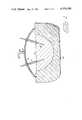
- FIG. 1is a schematic vertical sectional view showing in-situ vitrification
- FIG. 2is a schematic perspective view showing a vitrification process underway along a buried trench
- FIG. 3is a schematic view illustrating preparation of a trench for vitrification
- FIG. 4is a schematic view illustrating melting of soil about an initial conductive resistance path
- FIG. 5is a schematic view showing progressive vitrification
- FIG. 6is a schematic view showing the completed vitrification zone.
- This disclosureis concerned with in-situ vitrification of soil for any purpose. It is applicable to many uses such as soil stabilization, closing of bores and sealing of underground areas. It is specifically directed to waste disposal systems. While the following description was developed about waste disposal applications, the scope of this disclosure is not to be limited to the waste treatment field.
- Radioactively contaminated soilsuch as those that exist in low level waste burial grounds and plutonium burial trenches, are receiving public attention due to their potential for releasing radionuclides to the biosphere.
- Improved engineered barriersare required at some existing locations to contain the buried waste and surrounding soil to which some radionuclides have migrated.
- Engineering methods being considered to reduce the rate and extent of radionuclide releaseinclude, among others: excavation of the burial grounds followed by repackaging and reburial in shallow land repositories; or conversion of the waste to a less dispersable form.
- Current studiesindicate that the more desirable options currently available for reducing future risks to public safety are costly at best.
- waste materials and surrounding soilis immobilized in a stable glass, glass-ceramic, or partially devitrified glass waste form.
- the methodimmobilizes buried waste without removal of contaminated soil by imposing an electrical current between electrodes placed in the soil. Temperatures high enough for melting are created by imposing an electrical current between one or more pairs of electrodes placed in the soil.
- this methodcan be used to form a vitreous cover above buried waste locations or about the periphery of the waste materials. Such a cover would restrict the entry by plants or burrowing animals and minimize erosion and leaching of the buried waste materials.
- Vitrification of the soilis achieved by creating an electrically heated "in-situ melter.”
- heatis generated in molten glass by passing electrical current between electrodes submerged in the melt.
- Molten glass, heat and electric currentare typically contained by high temperature ceramic materials known as refractories.
- electrodesare inserted into the ground as the waste site and soil replaces the refractory to contain and insulate the melter.
- a portable insulated dome connected to a gas scrubbercan be used as a cover enclosing the ground surface above the melter. Heat losses can also be minimized by maintenance of a cover of unmelted material over the molten pool of sub-surface soil. This can be accomplished by starting up the melter below ground level or by placing overburden on the area prior to start up.
- FIG. 1schematically illustrates in-situ vitrification.
- a pair of upright electrodes 10project into a pool of molten soil 11 formed by the heating of soil and any included buried materials in the space between and immediately surrounding the electrodes 10.
- the electrodes 10are suspended in generally upright positions spaced from one another from an insulated cover or dome 12. They are supplied with electrical current through suitable conductors (not shown) operatively connected to an electrical source of power. Portions of the electrodes 10 can be covered by protective coatings or by a surrounding jacket 19 to prevent oxidation or deterioration of the electrodes along the length of electrode exposed above the pool of molten glass 11.
- the dome 12which is not restricted to hemispherical shapes but may be any shape desired, is vented at 13. Gaseous byproducts that result from the vitrification process can be collected through a conduit 14 for scrubbing or other gas treatment purposes.
- the pool of molten soil 11is surrounded by unmelted soil 15, which acts as an insulating refractory.
- this methodcan be applied to the in-situ solidification of any soil mass.
- the methodinvolves the insertion of at least one pair of electrodes into the soil at locations spanning at least a portion of the soil mass to cause melting of soil in the vicinity of the electrodes.
- Electrical currentis passed through the soil and other materials between the subsoil portions of the electrodes 10 by application of current to them to heat the materials to the soil melting temperature by establishing a current carrying pathway between the electrodes. Once this current carrying pathway is established in a pool of molten soil and/or other materials such as shown at 11 in FIG. 1, the application of current is continued until the desired depth of soil between electrodes 10 has been melted. Application of current to the electrodes is then terminated to permit cooling and solidification of the soil and any remaining materials into a vitrified mass.
- FIGS. 3 through 6schematically illustrate the process steps involved in the application of this method to vitrification of soil and waste materials buried in an elongated trench.
- the soilis again shown at 15 and the electrodes are again shown at 10.
- Buried waste materialis illustrated as being stored within containers 16 within an elongated subsurface trench having an outline shown by lines 17.
- molten sodium hydroxide methodmight be used, whereby a layer of sodium hydroxide between electrodes 10 is heated to its melting point (300° C.). At this point electrical conductivity between the electrodes 10 is obtained to create sufficient further rise in soil temperature for initial melting of the adjacent soil structure.
- An alternative methodinvolves heating of a sacrificial resistance element. A metal resistance coil or wire arranged between the electrodes 10 would create sufficient heat for initial melting of the soil. The coil would be eventually consumed in the molten soil.
- Chemical reagentsmight be added to the soil to result in a highly exothermic chemical reaction, such as a thermite reaction, generating sufficient heat to melt the soil.
- graphitemight be placed between the electrodes to conduct electricity in a resistance path from ambient temperature to elevated temperatures sufficiently high to sustain soil melting conditions.
- FIGS. 3 through 6The last-described startup method is illustrated in FIGS. 3 through 6.
- a horizontal layer of graphite 18is arranged between electrodes 10 to provide a conductive resistance path across them.
- the application of current to the electrodes 10will then heat the graphite 18 and raise the temperature of the soil about the conductive resistance path to its melting temperature.
- FIG. 4This is illustrated schematically in FIG. 4, where a liquid glass pool 20 is shown as it is forming about the graphite layer 18.
- the graphite layer 18 and liquid pool 20establish a current-carrying pathway between electrodes 10 which progressively enlarged as the application of current to electrodes 10 is continued.
- FIG. 5illustrates the process as the liquid pool 20 enlarged both laterally and vertically downward, engulfing the waste materials in containers 16 and raising the temperature of these waste materials to the melting temperature of the surrounding soil.
- the waste materialswill be melted, pyrolized or dissolved in the molten soil mass, depending upon their specific composition.
- FIG. 6illustrates complete melting of the waste materials and surrounding soil within the trench confines between the pair of electrodes 10. When the materials have been totally melted, the application of current to the electrodes 10 can be terminated. The electrodes can then be removed for reuse if desired.
- melting of the soilcan be terminated prior to complete melting of the burial waste materials if only a cover of vitreous material is desired.
- This methodreadily lends itself to the control necessary to cover or encapsulate waste materials buried in soil, as well as to produce a homogeneous vitrified mass of soil and waste materials components.
- the resulting vitrified masswill be in the form of a glass, a glass ceramic, or a partially devitrified glass, with crystals and glass dispersed within a solid matrix. Metals within the mass might be dissolved in the glass or will form solid masses at its lower boundaries.
- the choice of electrode material and proper electrode placementmust be related to the needs to maximize electrode life, to achieve proper melting and to contain the melter to a specific area.
- rod-shaped molybdenum or other high temperature materialscan be used as the electrode material to allow continuous operation at temperatures up to 1500° C. This will accommodate the typical melting temperature of most soils, which is usually below 1500° C. Since molybdenum oxidizes rapidly in air at temperatures above 600° C., a cooled jacket, an oxygen impervious coating, or other physical protection must be provided about exposed electrode surfaces.
- the electrodescan be vertically adjustable for changing the depth of the melter and for feeding the electrodes downwardly into the molten pool of material as the electrodes are consumed slowly by the melting process.
- the electrodescan be either stationary or moving.
- the drawingsillustrate the method utilizing stationary electrodes, but it is to be understood that the electrodes could be mounted on a crawler moved horizontally along the area to be stabilized. Heat from the electric current will melt the soil ahead of the moving electrodes. The melted soil will solidify after the electrodes pass.
- rod electrodesare driven or drilled into the ground spanning the waste material location.
- a two phase electrode arrangement with four electrodes equidistant from each otherappears most suitable because of the even firing distribution of electrical current between the pairs of electrodes.
- Thermocoupleswere placed in the soil in numerous locations to monitor the vitrification zone and obtain heat transfer data.
- the 20-cm long molybdenum electrodes with stainless steel extensionswere placed in the soil at a 30 cm separation with a layer of graphite spread between them for startup.
- An effluent sampling systemwas installed on the apparatus for determining radionuclide volatility and identifying combustion products.
- a container including samples of cloth, plastic, rubber, metal, ceramic, glass and concrete materialswas buried below the surface of the soil.
- Nonradioactive isotopes of Cs, Ru, and Srwere added to soil placed in the container and mixed with a 15-cm ⁇ 2-cm thick layer of soil located directly below the container.
- flaked graphitewas placed between and behind the electrodes in a trench 44 cm long, 5 cm deep and 2.5 cm wide.
- the graphitewas placed in the lower 2.5 cm of the trench and then covered with 2.5 cm of soil.
- the resistance of the graphite layerwas varied as necessary for these tests by physically disturbing the graphite layer.
- the voltageranged between 180 and 220 volts as the current was about 30 amps.
- the completed testyielded a vitrified mass of 48.6 kg in 93/4 hours.
- the vitrified zoneencompassed all of the container and simulated contaminated soil. Metal ingots from the metallic wastes were found at two locations at the bottom of the vitrified zone.
- the carbon monoxide content in the evolved gasis high in samples 1 and 4.
- Sample 1was taken when the graphite startup layer was oxidizing.
- Sample 4was taken when the combustible container of simulated wastes was being encompassed by the melt.
- the initial prevalance of carbon monoxideis apparently the result of incomplete combustion of the graphite used during startup.
- the high carbon monoxide level in sample 4probably resulted from the gaseous temperatures being too low to permit complete combustion of the gases as they reached the oxidizing conditions at the surface of the soil. Apparently cooling of the gases resulted upon passing through the relatively cold crust that existed above the melt zone during this portion of the test.
- FIG. 2schematically illustrates the above-ground equipment that might be used in conjunction with this process.
- a burial trenchis outlined by lines 17.
- a previously vitrified zone along the trenchis shown at 21.
- Drilled holes 22are located along the sides of the trench for reception of electrodes 10. The drawing shows an electrode 10a being lowered into a hole 22 by a mobile crane 23.
- the electrodes 10 in this exemplary apparatusare supported in groups of four within portable rigid frames shown at 24. These frames support electrical insulators for the individual electrodes 10, as well as a protective hood 25 made of glass impervious material and surrounded by a skirt 26 providing sealing engagement with the soil surfaces.
- Electrodes 10Electrical power is provided to the electrodes 10 through high voltage distribution lines 27 feeding a portable substation and control unit generally illustrated at 28. The required form of electrical power is then fed to supply lines illustrated at 30, which lead to the individual electrodes 10.
- the frames 24could be movably supported on wheels or tracks for transport along the length of trench 17.
- the framecan be self-propelled or externally moved at a speed corresponding to the rate of soil melting, thereby keeping the electrodes within the pool of molten material.
Landscapes
- Engineering & Computer Science (AREA)
- Chemical & Material Sciences (AREA)
- Life Sciences & Earth Sciences (AREA)
- Environmental & Geological Engineering (AREA)
- Organic Chemistry (AREA)
- Soil Sciences (AREA)
- Structural Engineering (AREA)
- Materials Engineering (AREA)
- General Engineering & Computer Science (AREA)
- Civil Engineering (AREA)
- Paleontology (AREA)
- Mining & Mineral Resources (AREA)
- General Life Sciences & Earth Sciences (AREA)
- Agronomy & Crop Science (AREA)
- Physics & Mathematics (AREA)
- Thermal Sciences (AREA)
- Chemical Kinetics & Catalysis (AREA)
- Electrochemistry (AREA)
- Processing Of Solid Wastes (AREA)
- Investigation Of Foundation Soil And Reinforcement Of Foundation Soil By Compacting Or Drainage (AREA)
- Road Paving Structures (AREA)
Abstract
Description
TABLE I ______________________________________ Hanford Soil Composition Material Wt % ______________________________________ SiO.sub.2 62.34 Al.sub.2 O.sub.3 10.97 Fe.sub.2 O.sub.3 6.83 TiO.sub.2 1.10 Ca 2.28 Mg 1.29 Na 1.91 K 1.57 C .68 N .10 S .03 H.sub.2 O + oxides 10.90 ______________________________________
TABLE 2 ______________________________________ Mass Spectrometric Gas Analysis Sample Number (mole %) 1 2 3 4 5 6 ______________________________________ CO.sub.2 0.47 0.17 0.21 0.22 0.17 0.21 Ar 9.93 0.92 9.95 0.93 0.97 0.97 O.sub.2 19.8 21.1 21.2 21.2 21.2 21.2 N.sub.2 76. 77.4 76.9 76.5 76.9 76.9 CO 2.2 0.4 0.7 1.1 0.7 0.7 He 0.01 0.01 0.01 0.01 0.01 0.01 H.sub.2 0.01 0.01 0.01 0.04 0.02 0.01 CH.sub.4 0.01 0.01 0.01 0.01 0.01 0.01 ______________________________________
TABLE 3 ______________________________________ VITRIFICATION AND SOIL ANALYSIS (wt %) Anal- SP-1 SP-2 SP-3 SP-4 SP-5 SP-6 SP-7 ysis ______________________________________ Al.sub.2 O.sub.3 9.80 13.10 13.40 13.60 13.70 13.70 10.10 11.70 B.sub.2 O.sub.3 .12 .08 .04 .03 .05 .07 .58 BaO .06 .08 .08 .08 .08 .08 .06 .08 CaO 4.23 6.78 6.79 6.99 7.01 6.92 5.04 4.58 Ce.sub.2 O.sub.3 .03 .05 Co.sub.2 O.sub.3 .01 .02 .01 .02 .02 .01 .03 .03 Cr.sub.2 O.sub.3 .03 .05 .02 .02 CuO .03 .01 .02 .02 Fe.sub.2 O.sub.3 11.70 7.21 7.32 7.55 7.41 7.50 29.10 6.60 Gd.sub.2 O.sub.3 .01 .03 MgO 2.22 3.56 3.63 3.27 3.70 3.71 2.68 2.32 MnO.sub.2 .14 .23 .25 .27 .23 .22 .22 .15 MoO.sub.2 .01 .01 .01 .03 .03 .02 .02 .02 Na.sub.2 O.sub.3 3.30 4.54 4.73 4.95 5.10 4.36 4.25 5.69 Nd.sub.2 O.sub.3 .01 .01 .04 P.sub.2 O.sub.5 .47 .30 .16 .18 .31 1.11 .44 PbO .06 .09 RuO.sub.2 .07 SiO.sub.2 63.30 59.50 58.0 58.2 60.10 60.60 56.10 61.80 SrO .03 .04 .05 .05 .05 .05 .05 .05 TiO.sub.2 1.54 1.94 1.97 2.02 2.00 2.00 2.00 1.15 Zn .02 ZrO.sub.2 .02 .05 .04 .04 .04 .05 .04 .04 TOTAL 97.00 97.50 97.00 97.00 99.60 99.60 111.50 95.00 ______________________________________
Claims (15)
Priority Applications (7)
| Application Number | Priority Date | Filing Date | Title |
|---|---|---|---|
| US06/251,663US4376598A (en) | 1981-04-06 | 1981-04-06 | In-situ vitrification of soil |
| GB8208257AGB2096209B (en) | 1981-04-06 | 1982-03-22 | In-situ vitrification of soil |
| CA000399046ACA1160668A (en) | 1981-04-06 | 1982-03-22 | In-situ vitrification of soil |
| FR8205866AFR2502989B1 (en) | 1981-04-06 | 1982-04-05 | PROCESS FOR IN SITU VITRIFICATION OF THE SOIL, PARTICULARLY FOR THE CONTAINMENT OF RADIOACTIVE WASTE |
| IT20587/82AIT1150761B (en) | 1981-04-06 | 1982-04-05 | SOIL VITRIFICATION PROCEDURE |
| DE3212851ADE3212851C2 (en) | 1981-04-06 | 1982-04-06 | In-situ glazing of soil |
| JP57057176AJPS57178023A (en) | 1981-04-06 | 1982-04-06 | Scene solidification of ground |
Applications Claiming Priority (1)
| Application Number | Priority Date | Filing Date | Title |
|---|---|---|---|
| US06/251,663US4376598A (en) | 1981-04-06 | 1981-04-06 | In-situ vitrification of soil |
Publications (2)
| Publication Number | Publication Date |
|---|---|
| US4376598Atrue US4376598A (en) | 1983-03-15 |
| US4376598B1 US4376598B1 (en) | 1989-10-17 |
Family
ID=22952899
Family Applications (1)
| Application Number | Title | Priority Date | Filing Date |
|---|---|---|---|
| US06/251,663Expired - LifetimeUS4376598A (en) | 1981-04-06 | 1981-04-06 | In-situ vitrification of soil |
Country Status (7)
| Country | Link |
|---|---|
| US (1) | US4376598A (en) |
| JP (1) | JPS57178023A (en) |
| CA (1) | CA1160668A (en) |
| DE (1) | DE3212851C2 (en) |
| FR (1) | FR2502989B1 (en) |
| GB (1) | GB2096209B (en) |
| IT (1) | IT1150761B (en) |
Cited By (71)
| Publication number | Priority date | Publication date | Assignee | Title |
|---|---|---|---|---|
| US4581163A (en)* | 1982-02-08 | 1986-04-08 | Kraftwerk Union Aktiengesellschaft | Method for conditioning weakly to medium-active wastes |
| US4670634A (en)* | 1985-04-05 | 1987-06-02 | Iit Research Institute | In situ decontamination of spills and landfills by radio frequency heating |
| US4776409A (en)* | 1984-09-04 | 1988-10-11 | Manchak Frank | Insitu waste impoundment treating apparatus and method of using same |
| US4793656A (en)* | 1987-02-12 | 1988-12-27 | Shell Mining Company | In-situ coal drying |
| US4838733A (en)* | 1988-12-05 | 1989-06-13 | Katz Albert A | Landfill compaction |
| US4842448A (en)* | 1987-11-12 | 1989-06-27 | Drexel University | Method of removing contaminants from contaminated soil in situ |
| US4844839A (en)* | 1984-09-04 | 1989-07-04 | Manchak Frank | In situ treatment and analysis of wastes |
| US4844807A (en)* | 1984-09-04 | 1989-07-04 | Manchak Frank | Insitu hazardous waste treating apparatus and method of using same |
| US4900196A (en)* | 1987-11-20 | 1990-02-13 | Iit Research Institute | Confinement in porous material by driving out water and substituting sealant |
| WO1990006402A1 (en)* | 1988-12-08 | 1990-06-14 | Battelle Memorial Institute | Initiating in-situ vitrification using an imgregnated cord |
| US4956535A (en)* | 1987-06-08 | 1990-09-11 | Battelle Memorial Institute | Electrode systems for in situ vitrification |
| US4957393A (en)* | 1988-04-14 | 1990-09-18 | Battelle Memorial Institute | In situ heating to detoxify organic-contaminated soils |
| US5011329A (en)* | 1990-02-05 | 1991-04-30 | Hrubetz Exploration Company | In situ soil decontamination method and apparatus |
| US5024556A (en)* | 1987-06-08 | 1991-06-18 | Battelle Memorial Institute | System for enhanced destruction of hazardous wastes by in situ vitrification of soil |
| US5100259A (en)* | 1988-10-07 | 1992-03-31 | Battelle Memorial Institute | Cold cap subsidence for in situ vitrification and electrodes therefor |
| US5101899A (en)* | 1989-12-14 | 1992-04-07 | International Royal & Oil Company | Recovery of petroleum by electro-mechanical vibration |
| US5114277A (en)* | 1991-02-22 | 1992-05-19 | Battelle Memorial Institute | Vitrified underground structures |
| US5134946A (en)* | 1991-07-22 | 1992-08-04 | Poovey Gary N | Neutralizer for toxic and nuclear waste |
| US5169263A (en)* | 1991-05-23 | 1992-12-08 | Shell Oil Company | In-situ soil decontamination process with sub-surface vapor recovery |
| US5181795A (en)* | 1992-08-19 | 1993-01-26 | Circeo Jr Louis J | In-situ landfill pyrolysis, remediation and vitrification |
| US5181797A (en)* | 1992-01-29 | 1993-01-26 | Circeo Jr Louis J | In-situ soil stabilization method and apparatus |
| US5190628A (en)* | 1992-02-25 | 1993-03-02 | Bibler Jane P | Method and apparatus for removing ions from soil |
| US5190405A (en)* | 1990-12-14 | 1993-03-02 | Shell Oil Company | Vacuum method for removing soil contaminants utilizing thermal conduction heating |
| US5193934A (en)* | 1991-05-23 | 1993-03-16 | Shell Oil Company | In-situ thermal desorption of contaminated surface soil |
| US5209604A (en)* | 1991-04-09 | 1993-05-11 | Shell Oil Company | Soil decontamination |
| WO1993009888A1 (en)* | 1991-11-13 | 1993-05-27 | Battelle Memorial Institute | Heating to detoxify solid earthen material having contaminants |
| US5245120A (en)* | 1991-12-27 | 1993-09-14 | Physical Sciences, Inc. | Process for treating metal-contaminated materials |
| US5244310A (en)* | 1991-10-04 | 1993-09-14 | Shell Oil Company | In-situ soil heating press/vapor extraction system |
| US5251700A (en)* | 1990-02-05 | 1993-10-12 | Hrubetz Environmental Services, Inc. | Well casing providing directional flow of injection fluids |
| US5271693A (en)* | 1992-10-09 | 1993-12-21 | Shell Oil Company | Enhanced deep soil vapor extraction process and apparatus for removing contaminants trapped in or below the water table |
| US5276253A (en)* | 1992-09-09 | 1994-01-04 | Circeo Jr Louis J | In-situ remediation and vitrification of contaminated soils, deposits and buried materials |
| WO1994004761A1 (en)* | 1992-08-19 | 1994-03-03 | Circeo Louis J Jr | Method and apparatus for in-situ treatment of landfill waste and contaminated soil |
| US5325795A (en)* | 1990-02-05 | 1994-07-05 | Hrubetz Environmental Services, Inc. | Mobile material decontamination apparatus |
| US5354355A (en)* | 1991-12-09 | 1994-10-11 | Battelle Memorial Institute | Earth melter and method of disposing of feed materials |
| US5420402A (en)* | 1992-02-05 | 1995-05-30 | Iit Research Institute | Methods and apparatus to confine earth currents for recovery of subsurface volatiles and semi-volatiles |
| US5443618A (en)* | 1991-12-09 | 1995-08-22 | Battelle Memorial Institute | Earth melter |
| US5449889A (en)* | 1992-10-30 | 1995-09-12 | E. I. Du Pont De Nemours And Company | Apparatus, system and method for dielectrically heating a medium using microwave energy |
| US5482402A (en)* | 1990-02-05 | 1996-01-09 | Hrubetz Environmental Services, Inc. | Method and apparatus for heating subsurface soil for decontamination |
| US5545804A (en)* | 1995-02-28 | 1996-08-13 | Exxon Research And Engineering Company | Metal fixation in oily waste contaminated soil using microwave radiation acting on in-situ produced coupling agent |
| US5556447A (en)* | 1995-01-23 | 1996-09-17 | Physical Sciences, Inc. | Process for treating metal-contaminated materials |
| US5564861A (en)* | 1995-06-06 | 1996-10-15 | Khudenko; Boris M. | Thermal method of in-situ soil treatment |
| US5566914A (en)* | 1993-07-20 | 1996-10-22 | Thomas; John E. | Sign support stake |
| US5586213A (en)* | 1992-02-05 | 1996-12-17 | Iit Research Institute | Ionic contact media for electrodes and soil in conduction heating |
| US5664911A (en)* | 1991-05-03 | 1997-09-09 | Iit Research Institute | Method and apparatus for in situ decontamination of a site contaminated with a volatile material |
| US5673285A (en)* | 1994-06-27 | 1997-09-30 | Electro-Pyrolysis, Inc. | Concentric electrode DC arc systems and their use in processing waste materials |
| US5678237A (en)* | 1996-06-24 | 1997-10-14 | Associated Universities, Inc. | In-situ vitrification of waste materials |
| US5749932A (en)* | 1996-03-29 | 1998-05-12 | Battelle Memorial Institute | Refractory electrodes for joule heating and methods of using same |
| US5769569A (en)* | 1996-06-18 | 1998-06-23 | Southern California Gas Company | In-situ thermal desorption of heavy hydrocarbons in vadose zone |
| NL1004739C2 (en)* | 1996-12-10 | 1998-07-02 | V G Fundatietechniek Bv | Purification of contaminated soil using isolation barrier - with simple gas removal and allowing building construction on land |
| WO1998056514A1 (en)* | 1997-06-10 | 1998-12-17 | Geosafe Corporation | Improved method of melting solid materials |
| US5879109A (en)* | 1997-02-20 | 1999-03-09 | Siemens Aktiengesellschaft | Process and apparatus for introducing an optical or electrical cable into solid ground |
| US5891011A (en)* | 1992-04-01 | 1999-04-06 | The United States Of America As Represented By The United States Department Of Energy | Vitrification of waste |
| US5910093A (en)* | 1994-12-23 | 1999-06-08 | Sliger; William A. | Starter tube for use in vitrification process |
| US6328102B1 (en) | 1995-12-01 | 2001-12-11 | John C. Dean | Method and apparatus for piezoelectric transport |
| US20020092849A1 (en)* | 1998-06-15 | 2002-07-18 | Petrenko Victor F. | High-frequency melting of interfacial ice |
| US20020096515A1 (en)* | 1998-06-15 | 2002-07-25 | Petrenko Victor F. | Prevention of ice formation by applying electric power to a liquid water layer |
| US20030000718A1 (en)* | 1998-06-15 | 2003-01-02 | Petrenko Victor F. | High-frequency de-icing of cableways |
| US20040242951A1 (en)* | 2001-09-25 | 2004-12-02 | Thompson Leo E. | Apparatus and method for melting of materials to be treated |
| US20050167099A1 (en)* | 2004-02-02 | 2005-08-04 | Phillips Steven J. | Method for the placement of subterranean electrodes |
| WO2006081442A1 (en) | 2005-01-28 | 2006-08-03 | Geosafe Corporation | Apparatus for rapid startup during in-container vitrification |
| US20080097138A1 (en)* | 2004-12-27 | 2008-04-24 | Mark Fuhrmann | Mercury contamination extraction |
| US20080185145A1 (en)* | 2007-02-05 | 2008-08-07 | Carney Peter R | Methods for extracting oil from tar sand |
| WO2014096737A1 (en)* | 2012-12-21 | 2014-06-26 | Saint-Gobain Isover | Glass manufacturing method using electric melting |
| RU2572205C1 (en)* | 2014-06-17 | 2015-12-27 | Федеральное государственное бюджетное образовательное учреждение высшего профессионального образования "Уфимский государственный нефтяной технический университет" | Processing method of hydrocarbon-bearing slurries in outdoor storages using uhf electromagnetic emission |
| US9624432B2 (en)* | 2013-06-28 | 2017-04-18 | Acm Technologies Inc. | Method of soil stabilization using fibers |
| US10137486B1 (en)* | 2018-02-27 | 2018-11-27 | Chevron U.S.A. Inc. | Systems and methods for thermal treatment of contaminated material |
| US20190367400A1 (en)* | 2013-07-31 | 2019-12-05 | Knauf Insulation | Submerged combustion melters and methods |
| US11085270B2 (en) | 2019-02-26 | 2021-08-10 | Henry Crichlow | In-situ vitrification of hazardous waste |
| CN114853314A (en)* | 2022-05-28 | 2022-08-05 | 中国人民解放军63653部队 | Glass electric melting solidification device capable of treating harmful solid wastes in situ |
| US11642709B1 (en) | 2021-03-04 | 2023-05-09 | Trs Group, Inc. | Optimized flux ERH electrode |
| US11979950B2 (en) | 2020-02-18 | 2024-05-07 | Trs Group, Inc. | Heater for contaminant remediation |
Families Citing this family (8)
| Publication number | Priority date | Publication date | Assignee | Title |
|---|---|---|---|---|
| DE59107535D1 (en)* | 1990-08-17 | 1996-04-18 | Weiss Gmbh & Co Leonhard | Device and method for eliminating gases, vapors, dusts and fumes that are hazardous to health by adsorption on surface-active substances |
| DE4426196C2 (en)* | 1994-07-23 | 1997-07-31 | Joachim Seckler | Process for sealing contaminated soil areas |
| GB9422062D0 (en)* | 1994-11-02 | 1994-12-21 | British Nuclear Fuels Plc | Immobilisation of pollutants in and by clay materials |
| GB9422058D0 (en)* | 1994-11-02 | 1994-12-21 | British Nuclear Fuels Plc | Method of producing a barrier to pollutant movement |
| DE102007022901A1 (en) | 2007-05-14 | 2008-11-20 | Ludger Boese | Floor, wall and ceiling reinforcing procedure for securing e.g. building layer of tunnel construction, involves supplying soil with amount of current impulse via number of bar electrodes to weld earth material |
| DE102019128106A1 (en)* | 2019-04-29 | 2020-10-29 | Fritz Kortschack | Special electrode arrangement for the targeted ohmic heating of different, electrically conductive or electrically conductive components containing goods or structures |
| US20230292406A1 (en)* | 2020-08-12 | 2023-09-14 | Fritz Kortschack | Special electrode arrangement for the targeted ohmic heating of different products or structures that are electrically conductive or contain electrically conductive constituents |
| CN116140346B (en)* | 2022-10-20 | 2024-08-27 | 中国人民解放军63653部队 | Material for in-situ glass solidification rapid electric starting and paving and application methods thereof |
Citations (13)
| Publication number | Priority date | Publication date | Assignee | Title |
|---|---|---|---|---|
| US1966760A (en)* | 1928-05-07 | 1934-07-17 | Irvine Lionel Robert Herborn | Construction of road pavements and other surfaces |
| US1993642A (en)* | 1932-03-19 | 1935-03-05 | Naamlooze Vennootschap Smeltbo | Apparatus for making bore holes |
| US2806818A (en)* | 1955-08-15 | 1957-09-17 | Kenneth C Howard | Electrolytic method for forming cavities in shale for storage of fluids |
| US3208674A (en)* | 1961-10-19 | 1965-09-28 | Gen Electric | Electrothermal fragmentation |
| US3443051A (en)* | 1965-07-23 | 1969-05-06 | Herbert August Puschner | Apparatus for heating meterial by means of microwave device |
| US3586624A (en)* | 1970-03-02 | 1971-06-22 | Werner Co | Waste disposal method and system |
| US3732697A (en)* | 1972-01-14 | 1973-05-15 | R Dickson | Waste disposal method and facility |
| US3988036A (en)* | 1975-03-10 | 1976-10-26 | Fisher Sidney T | Electric induction heating of underground ore deposits |
| US4094809A (en)* | 1977-02-23 | 1978-06-13 | The United States Of America As Represented By The United States Department Of Energy | Process for solidifying high-level nuclear waste |
| US4097401A (en)* | 1975-07-30 | 1978-06-27 | Gesellschaft Fur Kernforschung M.B.H. | Thermodynamically stable product for permanent storage and disposal of highly radioactive liquid wastes |
| US4119561A (en)* | 1976-03-20 | 1978-10-10 | Gesellschaft Fur Kernforschung M.B.H. | Method for avoiding malfunctions in the solidification of aqueous, radioactive wastes in a glass, glass ceramic or glass ceramic-like matrix |
| US4124483A (en)* | 1977-10-13 | 1978-11-07 | Christenson Lowell B | Apparatus and method of assisting pile driving by electro-osmosis |
| US4139488A (en)* | 1975-06-26 | 1979-02-13 | Vereinigte Edelstahlwerke Aktiengesellschaft | Method of preparing solid radioactive or toxic waste for long-term storage |
Family Cites Families (2)
| Publication number | Priority date | Publication date | Assignee | Title |
|---|---|---|---|---|
| GB725675A (en)* | 1952-04-17 | 1955-03-09 | Erich Sarapuu | The method of underground electrolinking and electro-carbonization of mineral fuels |
| GB756582A (en)* | 1954-01-15 | 1956-09-05 | Mini Of Fuel And Power | Improvements relating to the underground gasification of coal |
- 1981
- 1981-04-06USUS06/251,663patent/US4376598A/ennot_activeExpired - Lifetime
- 1982
- 1982-03-22GBGB8208257Apatent/GB2096209B/ennot_activeExpired
- 1982-03-22CACA000399046Apatent/CA1160668A/ennot_activeExpired
- 1982-04-05ITIT20587/82Apatent/IT1150761B/enactive
- 1982-04-05FRFR8205866Apatent/FR2502989B1/ennot_activeExpired
- 1982-04-06JPJP57057176Apatent/JPS57178023A/enactiveGranted
- 1982-04-06DEDE3212851Apatent/DE3212851C2/ennot_activeExpired - Lifetime
Patent Citations (13)
| Publication number | Priority date | Publication date | Assignee | Title |
|---|---|---|---|---|
| US1966760A (en)* | 1928-05-07 | 1934-07-17 | Irvine Lionel Robert Herborn | Construction of road pavements and other surfaces |
| US1993642A (en)* | 1932-03-19 | 1935-03-05 | Naamlooze Vennootschap Smeltbo | Apparatus for making bore holes |
| US2806818A (en)* | 1955-08-15 | 1957-09-17 | Kenneth C Howard | Electrolytic method for forming cavities in shale for storage of fluids |
| US3208674A (en)* | 1961-10-19 | 1965-09-28 | Gen Electric | Electrothermal fragmentation |
| US3443051A (en)* | 1965-07-23 | 1969-05-06 | Herbert August Puschner | Apparatus for heating meterial by means of microwave device |
| US3586624A (en)* | 1970-03-02 | 1971-06-22 | Werner Co | Waste disposal method and system |
| US3732697A (en)* | 1972-01-14 | 1973-05-15 | R Dickson | Waste disposal method and facility |
| US3988036A (en)* | 1975-03-10 | 1976-10-26 | Fisher Sidney T | Electric induction heating of underground ore deposits |
| US4139488A (en)* | 1975-06-26 | 1979-02-13 | Vereinigte Edelstahlwerke Aktiengesellschaft | Method of preparing solid radioactive or toxic waste for long-term storage |
| US4097401A (en)* | 1975-07-30 | 1978-06-27 | Gesellschaft Fur Kernforschung M.B.H. | Thermodynamically stable product for permanent storage and disposal of highly radioactive liquid wastes |
| US4119561A (en)* | 1976-03-20 | 1978-10-10 | Gesellschaft Fur Kernforschung M.B.H. | Method for avoiding malfunctions in the solidification of aqueous, radioactive wastes in a glass, glass ceramic or glass ceramic-like matrix |
| US4094809A (en)* | 1977-02-23 | 1978-06-13 | The United States Of America As Represented By The United States Department Of Energy | Process for solidifying high-level nuclear waste |
| US4124483A (en)* | 1977-10-13 | 1978-11-07 | Christenson Lowell B | Apparatus and method of assisting pile driving by electro-osmosis |
Non-Patent Citations (1)
| Title |
|---|
| Construction Methods and Equipment, pp. 70-82, Aug. 1954. |
Cited By (102)
| Publication number | Priority date | Publication date | Assignee | Title |
|---|---|---|---|---|
| US4581163A (en)* | 1982-02-08 | 1986-04-08 | Kraftwerk Union Aktiengesellschaft | Method for conditioning weakly to medium-active wastes |
| US4844839A (en)* | 1984-09-04 | 1989-07-04 | Manchak Frank | In situ treatment and analysis of wastes |
| US4776409A (en)* | 1984-09-04 | 1988-10-11 | Manchak Frank | Insitu waste impoundment treating apparatus and method of using same |
| US4844807A (en)* | 1984-09-04 | 1989-07-04 | Manchak Frank | Insitu hazardous waste treating apparatus and method of using same |
| US4670634A (en)* | 1985-04-05 | 1987-06-02 | Iit Research Institute | In situ decontamination of spills and landfills by radio frequency heating |
| US4793656A (en)* | 1987-02-12 | 1988-12-27 | Shell Mining Company | In-situ coal drying |
| US5024556A (en)* | 1987-06-08 | 1991-06-18 | Battelle Memorial Institute | System for enhanced destruction of hazardous wastes by in situ vitrification of soil |
| US4956535A (en)* | 1987-06-08 | 1990-09-11 | Battelle Memorial Institute | Electrode systems for in situ vitrification |
| US4842448A (en)* | 1987-11-12 | 1989-06-27 | Drexel University | Method of removing contaminants from contaminated soil in situ |
| US4900196A (en)* | 1987-11-20 | 1990-02-13 | Iit Research Institute | Confinement in porous material by driving out water and substituting sealant |
| US4957393A (en)* | 1988-04-14 | 1990-09-18 | Battelle Memorial Institute | In situ heating to detoxify organic-contaminated soils |
| US5316411A (en)* | 1988-04-14 | 1994-05-31 | Battelle Memorial Institute | Apparatus for in situ heating and vitrification |
| US5100259A (en)* | 1988-10-07 | 1992-03-31 | Battelle Memorial Institute | Cold cap subsidence for in situ vitrification and electrodes therefor |
| US4838733A (en)* | 1988-12-05 | 1989-06-13 | Katz Albert A | Landfill compaction |
| US5004373A (en)* | 1988-12-08 | 1991-04-02 | Battelle Memorial Institute | Method for initiating in-situ vitrification using an impregnated cord |
| WO1990006402A1 (en)* | 1988-12-08 | 1990-06-14 | Battelle Memorial Institute | Initiating in-situ vitrification using an imgregnated cord |
| US5101899A (en)* | 1989-12-14 | 1992-04-07 | International Royal & Oil Company | Recovery of petroleum by electro-mechanical vibration |
| US5011329A (en)* | 1990-02-05 | 1991-04-30 | Hrubetz Exploration Company | In situ soil decontamination method and apparatus |
| US5325795A (en)* | 1990-02-05 | 1994-07-05 | Hrubetz Environmental Services, Inc. | Mobile material decontamination apparatus |
| US5251700A (en)* | 1990-02-05 | 1993-10-12 | Hrubetz Environmental Services, Inc. | Well casing providing directional flow of injection fluids |
| US5482402A (en)* | 1990-02-05 | 1996-01-09 | Hrubetz Environmental Services, Inc. | Method and apparatus for heating subsurface soil for decontamination |
| US5261765A (en)* | 1990-02-05 | 1993-11-16 | Hrubetz Environments Services, Inc. | Method and apparatus for heating subsurface soil for decontamination |
| US5190405A (en)* | 1990-12-14 | 1993-03-02 | Shell Oil Company | Vacuum method for removing soil contaminants utilizing thermal conduction heating |
| US5114277A (en)* | 1991-02-22 | 1992-05-19 | Battelle Memorial Institute | Vitrified underground structures |
| WO1992014884A3 (en)* | 1991-02-22 | 1992-10-01 | Battelle Memorial Institute | Vitrified underground structures |
| US5209604A (en)* | 1991-04-09 | 1993-05-11 | Shell Oil Company | Soil decontamination |
| US5664911A (en)* | 1991-05-03 | 1997-09-09 | Iit Research Institute | Method and apparatus for in situ decontamination of a site contaminated with a volatile material |
| US5169263A (en)* | 1991-05-23 | 1992-12-08 | Shell Oil Company | In-situ soil decontamination process with sub-surface vapor recovery |
| US5193934A (en)* | 1991-05-23 | 1993-03-16 | Shell Oil Company | In-situ thermal desorption of contaminated surface soil |
| US5134946A (en)* | 1991-07-22 | 1992-08-04 | Poovey Gary N | Neutralizer for toxic and nuclear waste |
| US5244310A (en)* | 1991-10-04 | 1993-09-14 | Shell Oil Company | In-situ soil heating press/vapor extraction system |
| WO1993009888A1 (en)* | 1991-11-13 | 1993-05-27 | Battelle Memorial Institute | Heating to detoxify solid earthen material having contaminants |
| US5347070A (en)* | 1991-11-13 | 1994-09-13 | Battelle Pacific Northwest Labs | Treating of solid earthen material and a method for measuring moisture content and resistivity of solid earthen material |
| US5443618A (en)* | 1991-12-09 | 1995-08-22 | Battelle Memorial Institute | Earth melter |
| US5354355A (en)* | 1991-12-09 | 1994-10-11 | Battelle Memorial Institute | Earth melter and method of disposing of feed materials |
| US5245120A (en)* | 1991-12-27 | 1993-09-14 | Physical Sciences, Inc. | Process for treating metal-contaminated materials |
| WO1993015278A1 (en)* | 1992-01-29 | 1993-08-05 | Circeo Louis J Jr | In-situ soil stabilization method and apparatus |
| US5181797A (en)* | 1992-01-29 | 1993-01-26 | Circeo Jr Louis J | In-situ soil stabilization method and apparatus |
| JP3193049B2 (en) | 1992-01-29 | 2001-07-30 | ルイス ジェイ ジュニア サーシオ | Method and apparatus for stabilizing soil in situ |
| AU664738B2 (en)* | 1992-01-29 | 1995-11-30 | Salvador L Camacho | In-situ soil stabilization |
| US5586213A (en)* | 1992-02-05 | 1996-12-17 | Iit Research Institute | Ionic contact media for electrodes and soil in conduction heating |
| US5420402A (en)* | 1992-02-05 | 1995-05-30 | Iit Research Institute | Methods and apparatus to confine earth currents for recovery of subsurface volatiles and semi-volatiles |
| US5190628A (en)* | 1992-02-25 | 1993-03-02 | Bibler Jane P | Method and apparatus for removing ions from soil |
| US5891011A (en)* | 1992-04-01 | 1999-04-06 | The United States Of America As Represented By The United States Department Of Energy | Vitrification of waste |
| US5181795A (en)* | 1992-08-19 | 1993-01-26 | Circeo Jr Louis J | In-situ landfill pyrolysis, remediation and vitrification |
| WO1994004761A1 (en)* | 1992-08-19 | 1994-03-03 | Circeo Louis J Jr | Method and apparatus for in-situ treatment of landfill waste and contaminated soil |
| USRE35782E (en)* | 1992-08-19 | 1998-05-05 | Circeo, Jr.; Louis J. | In-situ landfill pyrolysis, remediation and vitrification |
| RU2103604C1 (en)* | 1992-08-19 | 1998-01-27 | Луис Дж.Джр. Киркео | Method of treatment of wastes including those contained in surface layers of soil |
| US5276253A (en)* | 1992-09-09 | 1994-01-04 | Circeo Jr Louis J | In-situ remediation and vitrification of contaminated soils, deposits and buried materials |
| USRE35715E (en)* | 1992-09-09 | 1998-01-13 | Circeo, Jr.; Louis J. | In-situ remediation and vitrification of contaminated soils, deposits and buried materials |
| US5271693A (en)* | 1992-10-09 | 1993-12-21 | Shell Oil Company | Enhanced deep soil vapor extraction process and apparatus for removing contaminants trapped in or below the water table |
| US5449889A (en)* | 1992-10-30 | 1995-09-12 | E. I. Du Pont De Nemours And Company | Apparatus, system and method for dielectrically heating a medium using microwave energy |
| US5566914A (en)* | 1993-07-20 | 1996-10-22 | Thomas; John E. | Sign support stake |
| US5673285A (en)* | 1994-06-27 | 1997-09-30 | Electro-Pyrolysis, Inc. | Concentric electrode DC arc systems and their use in processing waste materials |
| US5910093A (en)* | 1994-12-23 | 1999-06-08 | Sliger; William A. | Starter tube for use in vitrification process |
| US5556447A (en)* | 1995-01-23 | 1996-09-17 | Physical Sciences, Inc. | Process for treating metal-contaminated materials |
| US5545804A (en)* | 1995-02-28 | 1996-08-13 | Exxon Research And Engineering Company | Metal fixation in oily waste contaminated soil using microwave radiation acting on in-situ produced coupling agent |
| US5564861A (en)* | 1995-06-06 | 1996-10-15 | Khudenko; Boris M. | Thermal method of in-situ soil treatment |
| US6328102B1 (en) | 1995-12-01 | 2001-12-11 | John C. Dean | Method and apparatus for piezoelectric transport |
| US5749932A (en)* | 1996-03-29 | 1998-05-12 | Battelle Memorial Institute | Refractory electrodes for joule heating and methods of using same |
| US5769569A (en)* | 1996-06-18 | 1998-06-23 | Southern California Gas Company | In-situ thermal desorption of heavy hydrocarbons in vadose zone |
| US5678237A (en)* | 1996-06-24 | 1997-10-14 | Associated Universities, Inc. | In-situ vitrification of waste materials |
| NL1004739C2 (en)* | 1996-12-10 | 1998-07-02 | V G Fundatietechniek Bv | Purification of contaminated soil using isolation barrier - with simple gas removal and allowing building construction on land |
| US5879109A (en)* | 1997-02-20 | 1999-03-09 | Siemens Aktiengesellschaft | Process and apparatus for introducing an optical or electrical cable into solid ground |
| US6120430A (en)* | 1997-06-10 | 2000-09-19 | Hansen; James E. | Method of melting solid materials |
| WO1998056514A1 (en)* | 1997-06-10 | 1998-12-17 | Geosafe Corporation | Improved method of melting solid materials |
| US20020092849A1 (en)* | 1998-06-15 | 2002-07-18 | Petrenko Victor F. | High-frequency melting of interfacial ice |
| US20020096515A1 (en)* | 1998-06-15 | 2002-07-25 | Petrenko Victor F. | Prevention of ice formation by applying electric power to a liquid water layer |
| US20030000718A1 (en)* | 1998-06-15 | 2003-01-02 | Petrenko Victor F. | High-frequency de-icing of cableways |
| US6847024B2 (en)* | 1998-06-15 | 2005-01-25 | Trustees Of Dartmouth College | Prevention of ice formation by applying electric power to a liquid water layer |
| US7087876B2 (en) | 1998-06-15 | 2006-08-08 | The Trustees Of Dartmouth College | High-frequency melting of interfacial ice |
| US7164100B2 (en) | 1998-06-15 | 2007-01-16 | The Trustees Of Dartmouth College | High-frequency de-icing of cableways |
| US7211038B2 (en) | 2001-09-25 | 2007-05-01 | Geosafe Corporation | Methods for melting of materials to be treated |
| US20040242951A1 (en)* | 2001-09-25 | 2004-12-02 | Thompson Leo E. | Apparatus and method for melting of materials to be treated |
| US7429239B2 (en) | 2001-09-25 | 2008-09-30 | Geosafe Corporation | Methods for melting of materials to be treated |
| US20070208208A1 (en)* | 2001-09-25 | 2007-09-06 | Geosafe Corporation | Methods for melting of materials to be treated |
| US20050167099A1 (en)* | 2004-02-02 | 2005-08-04 | Phillips Steven J. | Method for the placement of subterranean electrodes |
| US7037040B2 (en) | 2004-02-02 | 2006-05-02 | Applied Geotechnical Engineering And Construction, Inc. (Agec, Inc.) | Method for the placement of subterranean electrodes |
| EP1732714A4 (en)* | 2004-03-25 | 2007-05-09 | Geosafe Corp | Apparatus and method for melting of materials to be treated |
| US20080097138A1 (en)* | 2004-12-27 | 2008-04-24 | Mark Fuhrmann | Mercury contamination extraction |
| US7692058B2 (en)* | 2004-12-27 | 2010-04-06 | Brookhaven Science Associates, Llc | Mercury contamination extraction |
| WO2006081442A1 (en) | 2005-01-28 | 2006-08-03 | Geosafe Corporation | Apparatus for rapid startup during in-container vitrification |
| US20080102413A1 (en)* | 2005-01-28 | 2008-05-01 | Thompson Leo E | Thermally Insulating Liner for In-Container Vitrification |
| US20080128271A1 (en)* | 2005-01-28 | 2008-06-05 | Geosafe Corporation | Apparatus for Rapid Startup During In-Container Vitrification |
| US20080167175A1 (en)* | 2005-01-28 | 2008-07-10 | Lowery Patrick S | Refractory Melt Barrier For In-Container Vitrification |
| US20080185145A1 (en)* | 2007-02-05 | 2008-08-07 | Carney Peter R | Methods for extracting oil from tar sand |
| US7617869B2 (en) | 2007-02-05 | 2009-11-17 | Superior Graphite Co. | Methods for extracting oil from tar sand |
| EP2935138B1 (en) | 2012-12-21 | 2021-04-28 | Saint-Gobain Isover | Glass manufacturing method using electric melting |
| CN104854053B (en)* | 2012-12-21 | 2019-04-16 | 圣戈班伊索福公司 | Pass through the glass-making processes of electrofusion |
| WO2014096737A1 (en)* | 2012-12-21 | 2014-06-26 | Saint-Gobain Isover | Glass manufacturing method using electric melting |
| US10000404B2 (en) | 2012-12-21 | 2018-06-19 | Saint-Gobain Isover | Glass manufacturing method using electric melting |
| CN104854053A (en)* | 2012-12-21 | 2015-08-19 | 圣戈班伊索福公司 | Glass manufacturing method using electric melting |
| US9624432B2 (en)* | 2013-06-28 | 2017-04-18 | Acm Technologies Inc. | Method of soil stabilization using fibers |
| US20190367400A1 (en)* | 2013-07-31 | 2019-12-05 | Knauf Insulation | Submerged combustion melters and methods |
| US11680004B2 (en)* | 2013-07-31 | 2023-06-20 | Knauf Insulation | Submerged combustion melters and methods |
| RU2572205C1 (en)* | 2014-06-17 | 2015-12-27 | Федеральное государственное бюджетное образовательное учреждение высшего профессионального образования "Уфимский государственный нефтяной технический университет" | Processing method of hydrocarbon-bearing slurries in outdoor storages using uhf electromagnetic emission |
| US10137486B1 (en)* | 2018-02-27 | 2018-11-27 | Chevron U.S.A. Inc. | Systems and methods for thermal treatment of contaminated material |
| US11085270B2 (en) | 2019-02-26 | 2021-08-10 | Henry Crichlow | In-situ vitrification of hazardous waste |
| US11979950B2 (en) | 2020-02-18 | 2024-05-07 | Trs Group, Inc. | Heater for contaminant remediation |
| US11642709B1 (en) | 2021-03-04 | 2023-05-09 | Trs Group, Inc. | Optimized flux ERH electrode |
| CN114853314A (en)* | 2022-05-28 | 2022-08-05 | 中国人民解放军63653部队 | Glass electric melting solidification device capable of treating harmful solid wastes in situ |
| CN114853314B (en)* | 2022-05-28 | 2023-06-23 | 中国人民解放军63653部队 | Glass electric melting solidifying device capable of in-situ processing harmful solid waste |
Also Published As
| Publication number | Publication date |
|---|---|
| JPH0243847B2 (en) | 1990-10-01 |
| FR2502989B1 (en) | 1986-01-31 |
| JPS57178023A (en) | 1982-11-02 |
| DE3212851C2 (en) | 1997-12-18 |
| US4376598B1 (en) | 1989-10-17 |
| GB2096209A (en) | 1982-10-13 |
| CA1160668A (en) | 1984-01-17 |
| DE3212851A1 (en) | 1982-10-21 |
| IT1150761B (en) | 1986-12-17 |
| GB2096209B (en) | 1985-02-27 |
| FR2502989A1 (en) | 1982-10-08 |
| IT8220587A0 (en) | 1982-04-05 |
Similar Documents
| Publication | Publication Date | Title |
|---|---|---|
| US4376598A (en) | In-situ vitrification of soil | |
| US5024556A (en) | System for enhanced destruction of hazardous wastes by in situ vitrification of soil | |
| US5673285A (en) | Concentric electrode DC arc systems and their use in processing waste materials | |
| EP0615598B1 (en) | Earth melter | |
| CA2596261A1 (en) | Overburden material for in-container vitrification | |
| US5114277A (en) | Vitrified underground structures | |
| EP0656973B1 (en) | Method for in-situ treatment of landfill waste and contaminated soil | |
| Buelt et al. | In-situ vitrification of soil | |
| Brouns et al. | In-situ vitrification of soil.[Patent application] | |
| JP2007530262A (en) | Method and apparatus for dissolving treatment substance | |
| Spalding et al. | Tracer-level radioactive pilot-scale test of in situ vitrification for the stabilization of contaminated soil sites at ORNL | |
| Jacobs et al. | In situ vitrification demonstration for the stabilization of buried wastes at the Oak Ridge National Laboratory | |
| US5910093A (en) | Starter tube for use in vitrification process | |
| Buelt et al. | The in situ vitrification integrated program: focusing an innovative solution on environmental restoration needs | |
| US5494376A (en) | Method and apparatus for controlling in situ waste remediation | |
| Spalding | Field demonstration of in situ vitrification for application to ORNL liquid waste disposal trenches | |
| Buelt et al. | In situ vitrification: Test results for a contaminated soil-melting process | |
| US5743937A (en) | Earth melter with rubble walls and method of use | |
| Liikala | In Situ Vitrification Applications to Hazardous Wastes | |
| Timmerman et al. | In situ vitrification: pilot-scale development | |
| Luey | In situ vitrification: Demonstrated capabilities and potential applications | |
| RU2130654C1 (en) | Pollutants control technique and waste disposal area | |
| Spalding et al. | Demonstrations of technology for remediation and closure of Oak Ridge National Laboratory waste disposal sites | |
| Callow et al. | In Situ Vitrification-Application to Buried Waste | |
| Oma et al. | In situ vitrification: application analysis for stabilization of transuranic waste |
Legal Events
| Date | Code | Title | Description |
|---|---|---|---|
| AS | Assignment | Owner name:UNITED STATES OF AMERICA AS REPRESENTED BY THE DEP Free format text:ASSIGNMENT OF ASSIGNORS INTEREST.;ASSIGNORS:BROUNS, RICHARD A.;BUELT, JAMES L.;BONNER, WILLIAM F.;REEL/FRAME:003921/0764 Effective date:19810326 | |
| STCF | Information on status: patent grant | Free format text:PATENTED CASE | |
| CC | Certificate of correction | ||
| MAFP | Maintenance fee payment | Free format text:PAYMENT OF MAINTENANCE FEE, 4TH YEAR, PL 96-517 (ORIGINAL EVENT CODE: M170); ENTITY STATUS OF PATENT OWNER: SMALL ENTITY Year of fee payment:4 | |
| RR | Request for reexamination filed | Effective date:19880505 | |
| B1 | Reexamination certificate first reexamination | ||
| MAFP | Maintenance fee payment | Free format text:PAYMENT OF MAINTENANCE FEE, 8TH YEAR, PL 96-517 (ORIGINAL EVENT CODE: M171); ENTITY STATUS OF PATENT OWNER: SMALL ENTITY Year of fee payment:8 | |
| FEPP | Fee payment procedure | Free format text:PAT HOLDER CLAIMS SMALL ENTITY STATUS - NONPROFIT ORG. (ORIGINAL EVENT CODE: SM03); ENTITY STATUS OF PATENT OWNER: SMALL ENTITY | |
| FEPP | Fee payment procedure | Free format text:PAYOR NUMBER ASSIGNED (ORIGINAL EVENT CODE: ASPN); ENTITY STATUS OF PATENT OWNER: SMALL ENTITY | |
| MAFP | Maintenance fee payment | Free format text:PAYMENT OF MAINTENANCE FEE, 12TH YR, SMALL ENTITY (ORIGINAL EVENT CODE: M285); ENTITY STATUS OF PATENT OWNER: SMALL ENTITY Year of fee payment:12 | |
| FEPP | Fee payment procedure | Free format text:PAYER NUMBER DE-ASSIGNED (ORIGINAL EVENT CODE: RMPN); ENTITY STATUS OF PATENT OWNER: SMALL ENTITY | |
| REFU | Refund | Free format text:REFUND OF EXCESS PAYMENTS PROCESSED (ORIGINAL EVENT CODE: R169); ENTITY STATUS OF PATENT OWNER: SMALL ENTITY |