US4376317A - Foldable step arrangement for beds - Google Patents
Foldable step arrangement for bedsDownload PDFInfo
- Publication number
- US4376317A US4376317AUS06/280,807US28080781AUS4376317AUS 4376317 AUS4376317 AUS 4376317AUS 28080781 AUS28080781 AUS 28080781AUS 4376317 AUS4376317 AUS 4376317A
- Authority
- US
- United States
- Prior art keywords
- foot
- section
- patient
- foot section
- legs
- Prior art date
- Legal status (The legal status is an assumption and is not a legal conclusion. Google has not performed a legal analysis and makes no representation as to the accuracy of the status listed.)
- Expired - Lifetime
Links
- 125000006850spacer groupChemical group0.000claimsdescription10
- 239000000463materialSubstances0.000claimsdescription8
- 238000003780insertionMethods0.000claimsdescription5
- 230000037431insertionEffects0.000claimsdescription5
- 230000003319supportive effectEffects0.000claims3
- NJPPVKZQTLUDBO-UHFFFAOYSA-NnovaluronChemical compoundC1=C(Cl)C(OC(F)(F)C(OC(F)(F)F)F)=CC=C1NC(=O)NC(=O)C1=C(F)C=CC=C1FNJPPVKZQTLUDBO-UHFFFAOYSA-N0.000claims2
- 230000005540biological transmissionEffects0.000description3
- 230000002093peripheral effectEffects0.000description3
- 230000004913activationEffects0.000description2
- 230000008901benefitEffects0.000description2
- 230000006378damageEffects0.000description2
- 208000027418Wounds and injuryDiseases0.000description1
- 230000003187abdominal effectEffects0.000description1
- 230000003213activating effectEffects0.000description1
- 230000037396body weightEffects0.000description1
- 230000009194climbingEffects0.000description1
- 230000000694effectsEffects0.000description1
- 230000005611electricityEffects0.000description1
- 230000005802health problemEffects0.000description1
- 208000014674injuryDiseases0.000description1
- 238000001990intravenous administrationMethods0.000description1
- 238000004519manufacturing processMethods0.000description1
- 239000007769metal materialSubstances0.000description1
- 239000002245particleSubstances0.000description1
- 230000000452restraining effectEffects0.000description1
- 230000007958sleepEffects0.000description1
- 239000000126substanceSubstances0.000description1
- 210000000115thoracic cavityAnatomy0.000description1
- 238000005303weighingMethods0.000description1
- 238000003466weldingMethods0.000description1
- 239000002023woodSubstances0.000description1
Images
Classifications
- A—HUMAN NECESSITIES
- A61—MEDICAL OR VETERINARY SCIENCE; HYGIENE
- A61G—TRANSPORT, PERSONAL CONVEYANCES, OR ACCOMMODATION SPECIALLY ADAPTED FOR PATIENTS OR DISABLED PERSONS; OPERATING TABLES OR CHAIRS; CHAIRS FOR DENTISTRY; FUNERAL DEVICES
- A61G7/00—Beds specially adapted for nursing; Devices for lifting patients or disabled persons
- A61G7/10—Devices for lifting patients or disabled persons, e.g. special adaptations of hoists thereto
- A61G7/16—Devices for lifting patients or disabled persons, e.g. special adaptations of hoists thereto converting a lying surface into a chair
- A—HUMAN NECESSITIES
- A61—MEDICAL OR VETERINARY SCIENCE; HYGIENE
- A61G—TRANSPORT, PERSONAL CONVEYANCES, OR ACCOMMODATION SPECIALLY ADAPTED FOR PATIENTS OR DISABLED PERSONS; OPERATING TABLES OR CHAIRS; CHAIRS FOR DENTISTRY; FUNERAL DEVICES
- A61G7/00—Beds specially adapted for nursing; Devices for lifting patients or disabled persons
- A61G7/002—Beds specially adapted for nursing; Devices for lifting patients or disabled persons having adjustable mattress frame
- A61G7/015—Beds specially adapted for nursing; Devices for lifting patients or disabled persons having adjustable mattress frame divided into different adjustable sections, e.g. for Gatch position
- A—HUMAN NECESSITIES
- A61—MEDICAL OR VETERINARY SCIENCE; HYGIENE
- A61G—TRANSPORT, PERSONAL CONVEYANCES, OR ACCOMMODATION SPECIALLY ADAPTED FOR PATIENTS OR DISABLED PERSONS; OPERATING TABLES OR CHAIRS; CHAIRS FOR DENTISTRY; FUNERAL DEVICES
- A61G2200/00—Information related to the kind of patient or his position
- A61G2200/10—Type of patient
- A61G2200/16—Type of patient bariatric, e.g. heavy or obese
- A—HUMAN NECESSITIES
- A61—MEDICAL OR VETERINARY SCIENCE; HYGIENE
- A61G—TRANSPORT, PERSONAL CONVEYANCES, OR ACCOMMODATION SPECIALLY ADAPTED FOR PATIENTS OR DISABLED PERSONS; OPERATING TABLES OR CHAIRS; CHAIRS FOR DENTISTRY; FUNERAL DEVICES
- A61G2203/00—General characteristics of devices
- A61G2203/10—General characteristics of devices characterised by specific control means, e.g. for adjustment or steering
- A61G2203/12—Remote controls
- A—HUMAN NECESSITIES
- A61—MEDICAL OR VETERINARY SCIENCE; HYGIENE
- A61G—TRANSPORT, PERSONAL CONVEYANCES, OR ACCOMMODATION SPECIALLY ADAPTED FOR PATIENTS OR DISABLED PERSONS; OPERATING TABLES OR CHAIRS; CHAIRS FOR DENTISTRY; FUNERAL DEVICES
- A61G7/00—Beds specially adapted for nursing; Devices for lifting patients or disabled persons
- A61G7/05—Parts, details or accessories of beds
- A61G7/053—Aids for getting into, or out of, bed, e.g. steps, chairs, cane-like supports
Definitions
- This inventionrelates to adjustable beds, and in particular to an adjustable bed specifically adapted for the care of morbidly obese patients.
- the morbidly obese patientthat is, one who weighs over twice as much as his or her maximum recommended body weight faces particular problems in hospital care and management.
- Such patientstypically weigh between 300 and 700 pounds and existing hospital beds are typically not sufficiently sturdy to support such bulk.
- the morbidly obese patientis often subject to a variety of associated health problems and may be unable to move from the bed without assistance.
- the bedthus becomes, in effect, a semi-permanent home in which the patient eats, sleeps, reads, watches television, and the like.
- the patientsare preferably transported in their beds to health care subfacilities. Further, such patients typically experience great difficulty just climbing into and out of bed and often have to be assisted to avoid injury or exhaustion.
- the principle objects of the present inventionare: to provide an adjustable bed specifically adapted for use by morbidly obese patients; to accommodates such a bed of great structural rigidity and strength to accommodate patients weighing between 300 and 700 pounds; to provide such a bed having means for adjusting a mattress and mattress support in various positions and attitudes for patient comfort and treatment; to provide such a bed which is easily movable from hospital rooms to corridors and health care facility rooms while with the patient thereon, and back again to the patient's room; to provide such a bed having a portable power means therewith for powered operation of associated life support systems for the patient; to provide such a bed having X-ray transparent panels thereon providing an area for insertion of X-ray film material to accommodate X-raying the patient while on the bed; to provide such a bed which accomodates an overhead traction frame for exercise and to assist in lifting the patient; to provide such a bed having a foldable foot rest therewith for comfort of the patient; to provide such a bed having a foldable step arrangement at the end of a foot
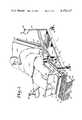
- FIG. 1is a perspective view of an adjustable bed embodying the present invention and with a morbidly obese patient reclining thereon.
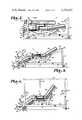
- FIG. 2is a side elevational view of the adjustable bed with head and foot and step arrangement sections in a first movement position.
- FIG. 3is a side elevational view of the adjustable bed with head and foot sections and step arrangement in a second movement position.
- FIG. 4is a side elevational view of the adjustable bed with head and foot sections and step arrangement in a third movement position.
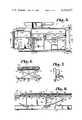
- FIG. 5is a top plan fragmentary view of the adjustable bed showing details thereof.
- FIG. 6is a fragmentary view of a foot section of the adjustable bed and showing an arrangement for raising a foot panel portion.
- FIG. 7is an enlarged fragmentary view of an adjustment motor means for tilting the head and foot sections.
- FIG. 8is a longitudinal sectional view of the adjustable bed taken along lines 8--8, FIG. 5.
- the reference numeral 1generally designates an adjustable bed embodying the present invention.
- the adjustable bed 1comprises a floor engaging frame 2 and a mattress support 3 having a head section 4, center section 5, and a foot section 6 pivotally interconnected. Foot rests 7 provide patient comfort and a foldable foot step arrangement 8 facilitates ease of entry and exit from the bed 1.
- Side arms 9are pivotally connected to opposite sides of the center section 5 and include rotation locking means at positions to provide support to confine a patient 10 on the bed and to selectively provide additional restive area.
- the frame 2is a stationary, ground engaging structure adapted to support the patient 10 and the mattress support 3 above the ground or floor surface.
- the frame 2includes a pair of parallel, longitudinally extending side rails 13 and 14 which are interconnected at the head of the frame by a laterally extending cross member 15.
- End posts 16are affixed to opposite ends of the side rails 13 and 14 and have wheels 17 pivotally affixed to lower ends thereof.
- the wheels 17are preferably provided with brakes 18 to selectively prevent inadvertent movement over the a floor surface.
- Upright end members 19have open lower ends which telescope over the end posts 16 and have upper ends with hand holds 20 affixed thereto to facilitate movement of the bed 1, as when wheeling the bed from room to room and through corridors and the like for movement of the patient 10.
- Upper ends of the end members 19are preferably provided with spring loaded end caps 22 which depress to provide access to the open interior of the respective end member 19 for insertion of an overhead traction frame 23, FIG. 4.
- the traction frame 23has a trapeze bar 24 for exercise of the patient or to assist and ease the patient into and off of the bed.
- intravenous administration equipment supports(not shown) may be inserted in the end members 19.
- Transverse cross braces 26 and 27extend between the side rails 13 and 14 at medial locations for mounting the mattress support 3.
- a platform 29, FIG. 8,extends between the side rails 13 and 14 headwardly of the cross brace 27 for support of a battery pack means described below.
- each of the sections 4, 5 and 6 of the mattress support 3has a generally rectangular shape, and includes a rigid, peripheral frame 30, such as of angle beam elements with interconnected end and side members 31 and 32.
- a flat plate or sheet 33overlies each of the peripheral frames 30 and is attached thereto by suitable fasteners, and preferably by means which will not interfere with the comfort of the bed, such as welds disposed along the frame 30 on the exterior side or top of the sheet 33.
- Each of the mattress sections 4, 5 and 6also includes a medial brace member 35 extending between the end members 31 of the respective frames 30.
- hold downs 37such as for restraining straps (not shown) to prevent harm to the patient are affixed to each of the side members 32 of the peripheral frame 30 of the head section 4 and the foot section 6.
- the adjacent end members 31 of adjoining sections 4, 5 and 6are reinforced by angle beams 39, FIG. 8, for additional structural rigidity.
- the angle beams 39are L-shaped in cross section and have one web disposed against the end member 31 and the other web contacting the bottom side of the flat plate or sheet 33 and extending along the end edge thereof.
- the adjacent frame end edges of the head section 4 and foot section 6are interconnected to the center section 5 by respective piano hinges 41.
- Outwardly extending hinge plates 42extend over a portion of the end of the flat plate or sheet 33 and have fasteners extending therethrough and securing the hinge plates 42 to the associated web portions of the angle beams 39.
- each lift means 50respectively extend between the frame 2 and the head and foot sections 4 and 6 for tilting the head and foot sections 4 and 6 with respect to the center section 5.
- each lift means 50includes a motor 51 rotatably driving a jack screw 52.
- the illustrated motor 51is operable in either rotational direction.
- One end of the helical jack screw 52is mounted in a transmission 53, FIG. 7 and is operably connected therewith whereby activation of the electric motor 51 rotates the screw 52.
- the other end of the screw 52is threadably connected in an elongated sleeve member 54 having a plurality of anti-friction balls mounted on the interior portion thereof which engage the root of the screw 54 for smooth, secure engagement therewith.
- Rotation of the screw 52 in one directionpulls the sleeve 54 convergingly toward the motor 51, and rotation of the screw in the opposite direction pushes the sleeve divergingly apart from the motor.
- Pin and clevis hinge connections 55 respectively at opposite ends of the lift means 50connect the motor 51 to the respective cross brace 26 or 27 and the end of the sleeve member 54 to the frame brace member 35.
- operation of the respective lift means 50 at the head and foot sections 4 and 6causes same to pivot about the respective hinges 41 and move either upwardly or downwardly as selected.
- Each motor 51 and transmission 53include internal braking means whereby the jack screw 52 is nonrotatable in the transmission 53 except when the motor 51 is actuated.
- Each of the motors 51is electrically connected with a circuit arrangement for selectively activating each of the motors and controlling the direction of rotation thereof. Preferably, each motor is activated by currents of 12 volts DC.
- a hand held switching controller 57is provided for operation of the motors 51 and has push button switches 58 therein for manipulation.
- a battery pack 60is positioned on one end of the platform 29 and connected by suitable circuitry to a battery charger. Switches activated by the controller 57 route electricity to the motors 51 for activation thereof.
- An outlet socket associated with the battery pack 60permits battery powered operation of life support systems such as resuscitators and the like.
- a diagnostic indicator panel in a battery pack cover member 61provides indication of battery charging and battery low voltage levels and additionally may include a buzzer for emission of a tone to indicate inadvertent disconnection of the battery pack 60 from a wall socket. If life support equipment, such as a resuscitator has electrical circuit lines thereof routed through the battery pack 60, such a buzzer would announce disconnection from the building power supply.
- panel members 63 of X-ray passive materialsuch as wood particle board are mounted in overlying relation to the respective head, center and foot sections 4, 5 and 6 and positioned a distance thereabove by spacers 64, thereby creating a cavity 65 between the panel members 63 and the associated section 4, 5 or 6.
- the spacers 64are arranged to provide unimpeded access to the cavity 65 for insertion of X-ray film material such as cassettes (not shown) for X-ray examination of thoracic, abdominal and leg regions.
- Expansible spacers 67are positioned between the panel member 63 and the underlying foot section 6 to permit elevation of the patient's legs.
- the expansible spacers 67include leg members 68 and 69 fixed together at a pivot 70 in a scissor jack arrangement.
- a lower end 71 of the leg 68 and an upper end 72 of the leg 67are pivotally connected at fixed locations respectively to the foot section plate or sheet 33 and the panel member 63.
- An upper end 74 of the leg 68is pivotally connected in a sliding hinge 75 to the lower surface of the panel member 63.
- a lower end 76 of the leg 69has a roller 77 mounted thereon.
- the roller 77is selectively engageable with a stop block 79 normally in the path of travel of the roller 77.
- the stop block 79has an inclined ramp surface 80 on an upper portion thereof.
- the panel member 63 of the foot section 6is grasped and pulled upwardly, urging the roller 77 over the ramp surface 80. The panel member 63 is then released so that the roller 77 rolls toward and engages the stop block 79 to prevent further movement, thereby positioning the panel member 63 in an upward or extended position.
- the panel member 63is merely grasped and tilted to the left, FIG. 6, to draw the roller 77 upwardly and over the stop block 79 whereupon the panel member 63 can be lowered.
- the foot rests 7are provided for comfort of the patient 10 when the foot section 6 is in a downwardly tilted position, FIGS. 3 and 4.
- the foot rests 7include a support structure 82 and rotatable foot members 83.
- the support structure 82has a cross bar 84 extending transversely underneath the foot section 7 and arm members 85 connected to opposite ends thereof and extending upwardly of the panel member 63 and any mattress and placed thereon.
- Respective pin 86extending upwardly from the arm members 85 provide a rotatable connection for the foot members 83 which are in the form of plates and have an upholstered surface for comfort.
- the foot members 83are swingable on the pins 86 from a position over the foot section 6 to a stowed position aligned longitudinally forwardly or rearwardly with the bed.
- the foot rests 7are adjustable longitudinally on the foot section 6 to adapt to the length of a particular patient 10 and in the illustrated example, have a spring loaded engagement pin 87 with a pawl end (not shown) extending through the lower portion of each arm member 85 and engageable with a selected one of a series of apertures 88 in the side members 32 of the frame 30 of the foot section 6.
- the spring loaded engagement pins 87 of each arm member 85are grasped and pulled outwardly and the foot rests 7 slid toward the head or foot end as necessary. Once properly positioned, the engagement pins 7 are released to snap into apertures generally aligned thereunder and thereby lock the foot rests 7 into position.
- the foldable foot step arrangement 8is affixed to the end of the foot section 6 to facilitate entry and exit of the patient 10 from the bed 1.
- the step arrangement 8comprises a hingedly interconnected parallelogram frame arrangement having upper and lower arms 90 and 91 and opposite head end, or forward, and foot end, or rearward, legs 92 and 93.
- the respective upper and lower arms 90 and 91 and the legs 92 and 93are of equal length.
- the arms 90 and 91 and legs 92 and 93preferably extend the width of the foot section 6 to provide ease of access to the patient.
- the arms 90 and 91 and legs 92 and 93are respectively rectangular and have spaced hinges 95 with hinge plates 96 secured to the marginal areas as by welding, rivets and the like.
- Rollers 97are rotatably mounted on the step arrangement 8 to facilitate unfolding and, in the illustrated example, are positioned in the hinge 95 between the lower arm 91 and foot end leg 92 with the hinge pin acting as the roller axle.
- the head end leg 93is secured to the foot section 6 adjacent the lower margin of the leg 93 so that the upper and lower arms 90 and 91 are substantially horizontal when the foot section 6 is fully swung downwardly, FIG. 4.
- Spaces pads 99are affixed to the bottom surface of the lower arm 91 and engage the floor when the step arrangement 8 is fully lowered.
- the pads 99 and the rollers 97thus provide sturdy support for the spaced legs 92 and 93 to support the upper arm 90 which forms a step platform when the step arrangement 8 is fully lowered.
- the upper surface of the arm 90 and the surfaces of the side rails 13 and 14have a non-skid substance thereon, such as in the form of an applique 100, FIG. 1.
- the side arms 9are positioned on opposite sides of the center section 5 and are pivotally mounted thereto for rotation toward and away from the center section 5.
- a two-piece mattressis emplaced and has a combination center and head section mattress 132 and a foot section mattress 133.
- a bolster 135 of triangular cross sectionis emplaced in the open area created by the side arms 9 in the outwardly swung position, FIG. 1, to provide additional restive area and support for the patient 10. Because of the great bulk of the morbidly obese patient and particularly the great width in the hip area of some morbidly obese women, the additional space or restive area acquired by affixing the side arms 9 at the outwardly swung position is of great benefit to provide comfort for the patient.
- the adjustable bed 1has standard size transverse dimensions to accommodate passage through a normal width hospital door and the bed cannot normally pass therethrough with the side arms 9 in the outwardly swung position.
- the bolster 135is simply lifted out and the side arm 9 swung to the upright position, FIG. 2, thereby providing confining support for the patient during movement and transport through corridors to various medical treatment rooms and the like.
Landscapes
- Health & Medical Sciences (AREA)
- Nursing (AREA)
- Life Sciences & Earth Sciences (AREA)
- Animal Behavior & Ethology (AREA)
- General Health & Medical Sciences (AREA)
- Public Health (AREA)
- Veterinary Medicine (AREA)
- Invalid Beds And Related Equipment (AREA)
Abstract
Description
Claims (10)
Priority Applications (1)
| Application Number | Priority Date | Filing Date | Title |
|---|---|---|---|
| US06/280,807US4376317A (en) | 1981-07-06 | 1981-07-06 | Foldable step arrangement for beds |
Applications Claiming Priority (1)
| Application Number | Priority Date | Filing Date | Title |
|---|---|---|---|
| US06/280,807US4376317A (en) | 1981-07-06 | 1981-07-06 | Foldable step arrangement for beds |
Publications (1)
| Publication Number | Publication Date |
|---|---|
| US4376317Atrue US4376317A (en) | 1983-03-15 |
Family
ID=23074741
Family Applications (1)
| Application Number | Title | Priority Date | Filing Date |
|---|---|---|---|
| US06/280,807Expired - LifetimeUS4376317A (en) | 1981-07-06 | 1981-07-06 | Foldable step arrangement for beds |
Country Status (1)
| Country | Link |
|---|---|
| US (1) | US4376317A (en) |
Cited By (31)
| Publication number | Priority date | Publication date | Assignee | Title |
|---|---|---|---|---|
| WO1989002260A1 (en)* | 1987-09-08 | 1989-03-23 | Siegener Feinmechanik Gmbh | Couch for care of the sick and elderly |
| US5095561A (en)* | 1991-05-09 | 1992-03-17 | Green Kenneth J | Invalid bed |
| WO1999000099A3 (en)* | 1997-06-26 | 1999-03-18 | Hill Rom Co Inc | Bariatric bed |
| US6076209A (en)* | 1996-12-26 | 2000-06-20 | Paul; Gerald S. | Articulation mechanism for a medical bed |
| US6349435B1 (en) | 1999-11-19 | 2002-02-26 | Herbert L. Mitchell | Bedrail attachments for engineered wood bedrail |
| EP1224923A1 (en)* | 2001-01-19 | 2002-07-24 | Hermann Bock GmbH | Bed, especially a medical and/or care bed |
| US6516479B1 (en)* | 2000-06-02 | 2003-02-11 | Burke Mobility Products, Inc. | Foldable rehabilitation bed for accommodating an obese person |
| US6536056B1 (en)* | 1996-11-18 | 2003-03-25 | John H. Vrzalik | Bariatric treatment system and related methods |
| US6694557B1 (en) | 1997-06-26 | 2004-02-24 | Hill-Rom Services, Inc. | Bariatric bed |
| US6789280B1 (en)* | 1996-12-26 | 2004-09-14 | Gerald S. Paul | Articulated medical bed |
| US20050229321A1 (en)* | 1996-11-18 | 2005-10-20 | Kci Licensing, Inc. | Bariatric treatment system and related methods |
| US20060000021A1 (en)* | 2002-05-17 | 2006-01-05 | Stephen Hayes | Profiling bed |
| US20060053555A1 (en)* | 2004-09-13 | 2006-03-16 | Craig Poulos | Bed having fixed length foot deck |
| US20060053562A1 (en)* | 2004-09-13 | 2006-03-16 | Craig Poulos | Mattress for a hospital bed |
| US20060059621A1 (en)* | 2004-09-13 | 2006-03-23 | Craig Poulos | Siderail for hospital bed |
| US20060059624A1 (en)* | 2004-09-13 | 2006-03-23 | Craig Poulos | Expandable width bed |
| US20060085914A1 (en)* | 2004-06-14 | 2006-04-27 | Steve Peterson | Adjustable bed for bariatric patients |
| US20060090261A1 (en)* | 1995-01-31 | 2006-05-04 | Kci Licensing, Inc. | Bariatric bed apparatus and methods |
| US20060220350A1 (en)* | 2005-03-31 | 2006-10-05 | Reef Rick R | Bariatric phase chair |
| US20080000028A1 (en)* | 2006-06-28 | 2008-01-03 | Stryker Corporation | Patient support |
| US20100005592A1 (en)* | 2008-06-27 | 2010-01-14 | Craig Poulos | Bed with modified foot deck |
| US20100031441A1 (en)* | 2008-08-05 | 2010-02-11 | Pascal Guguin | Bed with a Lateral Barrier Having a Tilt Feature |
| WO2010148047A3 (en)* | 2009-06-17 | 2011-03-31 | Masson Marcos V | Slidable cushion for a multi-purpose gurney |
| EP2308442A1 (en)* | 2009-10-12 | 2011-04-13 | Joh. Stiegelmeyer GmbH & Co. KG | Hospital and care bed with anti-tip element |
| US8864205B2 (en) | 2006-06-28 | 2014-10-21 | Stryker Corporation | Patient support with wireless data and/or energy transfer |
| US9265677B2 (en) | 2009-12-23 | 2016-02-23 | Piedmont 361, Llc | Hospital chair beds with stowable stand-assist supports |
| US20160346144A1 (en)* | 2015-05-28 | 2016-12-01 | Medical Positioning, Inc. | Low clearance medical imaging chair |
| CN109394446A (en)* | 2018-12-12 | 2019-03-01 | 广东东品美容医疗科技有限公司 | Multifunctional physiotherapeutic |
| US10898000B2 (en) | 2018-07-26 | 2021-01-26 | United Metal Fabricators, Inc. | Leg extension for procedure chair |
| US11090214B2 (en) | 2018-08-06 | 2021-08-17 | United Metal Fabricators, Inc. | Leg support assembly for medical examination device |
| US12150908B2 (en) | 2014-04-18 | 2024-11-26 | Kreg Medical, Inc. | Patient support with stand-up and sit features |
Citations (7)
| Publication number | Priority date | Publication date | Assignee | Title |
|---|---|---|---|---|
| US1607420A (en)* | 1923-11-23 | 1926-11-16 | Vinson Williams S | Invalid bed |
| US2452366A (en)* | 1944-08-11 | 1948-10-26 | Robert R Freund | Patient adjustable foot section for articulated beds |
| CA649038A (en)* | 1962-09-25 | Nawara Jozef | Therapeutic apparatus | |
| US3636573A (en)* | 1970-01-29 | 1972-01-25 | Con Tex Corp | Foldable mattress support |
| US3964786A (en)* | 1974-12-20 | 1976-06-22 | David Mashuda | Mechanized wheelchair |
| US4083599A (en)* | 1976-04-16 | 1978-04-11 | Gaffney Edward J | Lift chair with rocker and wheel frame attachments |
| US4183109A (en)* | 1978-04-21 | 1980-01-15 | Howell William H | Sectional bed |
- 1981
- 1981-07-06USUS06/280,807patent/US4376317A/ennot_activeExpired - Lifetime
Patent Citations (7)
| Publication number | Priority date | Publication date | Assignee | Title |
|---|---|---|---|---|
| CA649038A (en)* | 1962-09-25 | Nawara Jozef | Therapeutic apparatus | |
| US1607420A (en)* | 1923-11-23 | 1926-11-16 | Vinson Williams S | Invalid bed |
| US2452366A (en)* | 1944-08-11 | 1948-10-26 | Robert R Freund | Patient adjustable foot section for articulated beds |
| US3636573A (en)* | 1970-01-29 | 1972-01-25 | Con Tex Corp | Foldable mattress support |
| US3964786A (en)* | 1974-12-20 | 1976-06-22 | David Mashuda | Mechanized wheelchair |
| US4083599A (en)* | 1976-04-16 | 1978-04-11 | Gaffney Edward J | Lift chair with rocker and wheel frame attachments |
| US4183109A (en)* | 1978-04-21 | 1980-01-15 | Howell William H | Sectional bed |
Cited By (60)
| Publication number | Priority date | Publication date | Assignee | Title |
|---|---|---|---|---|
| WO1989002260A1 (en)* | 1987-09-08 | 1989-03-23 | Siegener Feinmechanik Gmbh | Couch for care of the sick and elderly |
| US5095561A (en)* | 1991-05-09 | 1992-03-17 | Green Kenneth J | Invalid bed |
| WO1992019203A1 (en)* | 1991-05-09 | 1992-11-12 | Green Kenneth J | Invalid bed |
| US20080289107A1 (en)* | 1995-01-31 | 2008-11-27 | Kci Licensing, Inc. | Bariatric Bed Apparatus and Methods |
| US7426760B2 (en) | 1995-01-31 | 2008-09-23 | Kci Licensing, Inc. | Bariatric bed apparatus and methods |
| US7827632B2 (en) | 1995-01-31 | 2010-11-09 | Vrzalik John H | Bariatric bed apparatus and methods |
| US20060090261A1 (en)* | 1995-01-31 | 2006-05-04 | Kci Licensing, Inc. | Bariatric bed apparatus and methods |
| US20030208847A1 (en)* | 1996-11-18 | 2003-11-13 | Kinetic Concepts, Inc. | Bariatric treatment system and related methods |
| US7346945B2 (en) | 1996-11-18 | 2008-03-25 | Kci Licensing, Inc. | Bariatric treatment system and related methods |
| US6536056B1 (en)* | 1996-11-18 | 2003-03-25 | John H. Vrzalik | Bariatric treatment system and related methods |
| US6904631B2 (en) | 1996-11-18 | 2005-06-14 | Kci Licensing, Inc. | Bariatric treatment system and related methods |
| US20050229321A1 (en)* | 1996-11-18 | 2005-10-20 | Kci Licensing, Inc. | Bariatric treatment system and related methods |
| US6076209A (en)* | 1996-12-26 | 2000-06-20 | Paul; Gerald S. | Articulation mechanism for a medical bed |
| US6789280B1 (en)* | 1996-12-26 | 2004-09-14 | Gerald S. Paul | Articulated medical bed |
| US6694557B1 (en) | 1997-06-26 | 2004-02-24 | Hill-Rom Services, Inc. | Bariatric bed |
| US6141806A (en)* | 1997-06-26 | 2000-11-07 | Hill-Rom, Inc. | Bariatric bed |
| WO1999000099A3 (en)* | 1997-06-26 | 1999-03-18 | Hill Rom Co Inc | Bariatric bed |
| US6349435B1 (en) | 1999-11-19 | 2002-02-26 | Herbert L. Mitchell | Bedrail attachments for engineered wood bedrail |
| US6516479B1 (en)* | 2000-06-02 | 2003-02-11 | Burke Mobility Products, Inc. | Foldable rehabilitation bed for accommodating an obese person |
| US20040154103A1 (en)* | 2001-01-19 | 2004-08-12 | Ernst Bock | Bed, particulary hospital and/or nursing bed |
| EP1224923A1 (en)* | 2001-01-19 | 2002-07-24 | Hermann Bock GmbH | Bed, especially a medical and/or care bed |
| US20060000021A1 (en)* | 2002-05-17 | 2006-01-05 | Stephen Hayes | Profiling bed |
| US7441291B2 (en)* | 2002-05-17 | 2008-10-28 | Huntleigh Technology Limited | Profiling bed |
| US20060085914A1 (en)* | 2004-06-14 | 2006-04-27 | Steve Peterson | Adjustable bed for bariatric patients |
| US20060059624A1 (en)* | 2004-09-13 | 2006-03-23 | Craig Poulos | Expandable width bed |
| US7743441B2 (en) | 2004-09-13 | 2010-06-29 | Kreg Therapeutics, Inc. | Expandable width bed |
| US8056160B2 (en) | 2004-09-13 | 2011-11-15 | Kreg Medical, Inc. | Siderail for hospital bed |
| US8069514B2 (en) | 2004-09-13 | 2011-12-06 | Kreg Medical, Inc. | Expandable width bed |
| US20060059621A1 (en)* | 2004-09-13 | 2006-03-23 | Craig Poulos | Siderail for hospital bed |
| US20060053562A1 (en)* | 2004-09-13 | 2006-03-16 | Craig Poulos | Mattress for a hospital bed |
| US20060053555A1 (en)* | 2004-09-13 | 2006-03-16 | Craig Poulos | Bed having fixed length foot deck |
| US7676862B2 (en) | 2004-09-13 | 2010-03-16 | Kreg Medical, Inc. | Siderail for hospital bed |
| US20100107335A1 (en)* | 2004-09-13 | 2010-05-06 | Craig Poulos | Siderail for hospital bed |
| US7779494B2 (en) | 2004-09-13 | 2010-08-24 | Kreg Therapeutics, Inc. | Bed having fixed length foot deck |
| US7757318B2 (en) | 2004-09-13 | 2010-07-20 | Kreg Therapeutics, Inc. | Mattress for a hospital bed |
| US20060220350A1 (en)* | 2005-03-31 | 2006-10-05 | Reef Rick R | Bariatric phase chair |
| US20080000028A1 (en)* | 2006-06-28 | 2008-01-03 | Stryker Corporation | Patient support |
| US12383450B2 (en) | 2006-06-28 | 2025-08-12 | Stryker Corporation | Patient support with energy transfer |
| US11793699B2 (en) | 2006-06-28 | 2023-10-24 | Stryker Corporation | Patient support with energy transfer |
| US10561551B2 (en) | 2006-06-28 | 2020-02-18 | Stryker Corporation | Patient support with energy transfer |
| US8864205B2 (en) | 2006-06-28 | 2014-10-21 | Stryker Corporation | Patient support with wireless data and/or energy transfer |
| US8056163B2 (en) | 2006-06-28 | 2011-11-15 | Stryker Corporation | Patient support |
| US20100005592A1 (en)* | 2008-06-27 | 2010-01-14 | Craig Poulos | Bed with modified foot deck |
| US9119753B2 (en) | 2008-06-27 | 2015-09-01 | Kreg Medical, Inc. | Bed with modified foot deck |
| US10617582B2 (en) | 2008-06-27 | 2020-04-14 | Kreg Medical, Inc. | Bed with modified foot deck |
| US12208041B2 (en) | 2008-06-27 | 2025-01-28 | Kreg Medical, Inc. | Bed with frame assembly |
| US7913334B2 (en)* | 2008-08-05 | 2011-03-29 | Pascal Guguin | Bed with a lateral barrier having a tilt feature |
| US20100031441A1 (en)* | 2008-08-05 | 2010-02-11 | Pascal Guguin | Bed with a Lateral Barrier Having a Tilt Feature |
| WO2010148047A3 (en)* | 2009-06-17 | 2011-03-31 | Masson Marcos V | Slidable cushion for a multi-purpose gurney |
| EP2308442A1 (en)* | 2009-10-12 | 2011-04-13 | Joh. Stiegelmeyer GmbH & Co. KG | Hospital and care bed with anti-tip element |
| US9265677B2 (en) | 2009-12-23 | 2016-02-23 | Piedmont 361, Llc | Hospital chair beds with stowable stand-assist supports |
| US12239594B2 (en) | 2014-04-18 | 2025-03-04 | Kreg Medical, Inc. | Patient support with stand-up and sit features |
| US12239593B2 (en) | 2014-04-18 | 2025-03-04 | Kreg Medical, Inc. | Patient support with stand-up and sit features |
| US12150908B2 (en) | 2014-04-18 | 2024-11-26 | Kreg Medical, Inc. | Patient support with stand-up and sit features |
| US10667976B2 (en)* | 2015-05-28 | 2020-06-02 | Medical Positioning, Inc. | Low clearance medical imaging chair |
| US20160346144A1 (en)* | 2015-05-28 | 2016-12-01 | Medical Positioning, Inc. | Low clearance medical imaging chair |
| US10898000B2 (en) | 2018-07-26 | 2021-01-26 | United Metal Fabricators, Inc. | Leg extension for procedure chair |
| US11090214B2 (en) | 2018-08-06 | 2021-08-17 | United Metal Fabricators, Inc. | Leg support assembly for medical examination device |
| CN109394446B (en)* | 2018-12-12 | 2023-10-20 | 广东东品美容医疗科技有限公司 | Multifunctional physiotherapy bed |
| CN109394446A (en)* | 2018-12-12 | 2019-03-01 | 广东东品美容医疗科技有限公司 | Multifunctional physiotherapeutic |
Similar Documents
| Publication | Publication Date | Title |
|---|---|---|
| US4376317A (en) | Foldable step arrangement for beds | |
| US4409695A (en) | Adjustable bed for morbidly obese patients | |
| US5996150A (en) | Cantilevered mobile bed/chair apparatus for safety patient transfer | |
| US6374436B1 (en) | Hospital bed | |
| US6427270B1 (en) | Cantilevered mobile bed/chair apparatus for safety patient transfer | |
| US6691349B2 (en) | Patient bed with leg lifter | |
| US8484773B2 (en) | Combined bed/chair transporter with leg lift | |
| US20060085914A1 (en) | Adjustable bed for bariatric patients | |
| US5060960A (en) | Combination wheelchair and lifting device | |
| US6112345A (en) | Hospital bed | |
| US4894876A (en) | Multipurpose maternity care bed | |
| US4999862A (en) | Wheelchair mounted invalid lift | |
| EP0420263B1 (en) | All purpose wheelchair | |
| US4240169A (en) | Patient transferring apparatus | |
| US5612515A (en) | Portable weighing scale having a pivotal weighing platform | |
| US6427263B1 (en) | Device for moving patients | |
| US5112076A (en) | Wheelchair with removable seat | |
| US6912746B2 (en) | Bed | |
| US10363187B2 (en) | Methods and apparatus for moving a patient from a reclining position to an upright sitting position | |
| JPS61255657A (en) | Hospital bed | |
| US9089464B2 (en) | Patient lifting device | |
| US20020116764A1 (en) | Bed with adjustable positions | |
| US20120104818A1 (en) | Portable, Powered Chair Lift | |
| US5007118A (en) | Head care station and kit and method for reclining the occupant of a wheelchair against a head support | |
| US4800599A (en) | Somatic support system |
Legal Events
| Date | Code | Title | Description |
|---|---|---|---|
| AS | Assignment | Owner name:BURKE, INC., P.O. BOX 1064, MISSION, KS. 66202 A Free format text:ASSIGNMENT OF ASSIGNORS INTEREST.;ASSIGNORS:RAINES, BILL D.;JOHNSTON, BRUCE L.;REEL/FRAME:003900/0113 Effective date:19810625 | |
| STCF | Information on status: patent grant | Free format text:PATENTED CASE | |
| MAFP | Maintenance fee payment | Free format text:PAYMENT OF MAINTENANCE FEE, 4TH YEAR, PL 96-517 (ORIGINAL EVENT CODE: M170); ENTITY STATUS OF PATENT OWNER: SMALL ENTITY Year of fee payment:4 | |
| MAFP | Maintenance fee payment | Free format text:PAYMENT OF MAINTENANCE FEE, 8TH YEAR, PL 96-517 (ORIGINAL EVENT CODE: M171); ENTITY STATUS OF PATENT OWNER: SMALL ENTITY Year of fee payment:8 | |
| FEPP | Fee payment procedure | Free format text:MAINTENANCE FEE REMINDER MAILED (ORIGINAL EVENT CODE: REM.); ENTITY STATUS OF PATENT OWNER: SMALL ENTITY | |
| FEPP | Fee payment procedure | Free format text:SURCHARGE FOR LATE PAYMENT, SMALL ENTITY (ORIGINAL EVENT CODE: M286); ENTITY STATUS OF PATENT OWNER: SMALL ENTITY | |
| MAFP | Maintenance fee payment | Free format text:PAYMENT OF MAINTENANCE FEE, 12TH YR, SMALL ENTITY (ORIGINAL EVENT CODE: M285); ENTITY STATUS OF PATENT OWNER: SMALL ENTITY Year of fee payment:12 | |
| FEPP | Fee payment procedure | Free format text:PAYOR NUMBER ASSIGNED (ORIGINAL EVENT CODE: ASPN); ENTITY STATUS OF PATENT OWNER: SMALL ENTITY |