US4375813A - Medical fluid flow rate controlling device - Google Patents
Medical fluid flow rate controlling deviceDownload PDFInfo
- Publication number
- US4375813A US4375813AUS06/233,095US23309581AUS4375813AUS 4375813 AUS4375813 AUS 4375813AUS 23309581 AUS23309581 AUS 23309581AUS 4375813 AUS4375813 AUS 4375813A
- Authority
- US
- United States
- Prior art keywords
- liquid
- chamber
- flow
- inlet
- gas phase
- Prior art date
- Legal status (The legal status is an assumption and is not a legal conclusion. Google has not performed a legal analysis and makes no representation as to the accuracy of the status listed.)
- Expired - Fee Related
Links
- 239000012530fluidSubstances0.000titleclaimsabstractdescription87
- 239000007788liquidSubstances0.000claimsabstractdescription186
- 239000012528membraneSubstances0.000claimsabstractdescription46
- 238000000034methodMethods0.000claimsabstractdescription8
- 238000001990intravenous administrationMethods0.000abstractdescription5
- 239000012071phaseSubstances0.000description22
- 238000007906compressionMethods0.000description12
- 230000006835compressionEffects0.000description11
- 230000002706hydrostatic effectEffects0.000description8
- 230000037452primingEffects0.000description8
- 230000002209hydrophobic effectEffects0.000description7
- 239000000463materialSubstances0.000description5
- 229920001821foam rubberPolymers0.000description3
- 239000003978infusion fluidSubstances0.000description3
- 229920002379silicone rubberPolymers0.000description3
- 239000004945silicone rubberSubstances0.000description3
- PPBRXRYQALVLMV-UHFFFAOYSA-NStyreneChemical compoundC=CC1=CC=CC=C1PPBRXRYQALVLMV-UHFFFAOYSA-N0.000description2
- 239000003814drugSubstances0.000description2
- 229940079593drugDrugs0.000description2
- 238000012986modificationMethods0.000description2
- 230000004048modificationEffects0.000description2
- 239000011148porous materialSubstances0.000description2
- 230000007704transitionEffects0.000description2
- 239000010963304 stainless steelSubstances0.000description1
- 206010001526Air embolismDiseases0.000description1
- 229910000589SAE 304 stainless steelInorganic materials0.000description1
- FAPWRFPIFSIZLT-UHFFFAOYSA-MSodium chlorideChemical compound[Na+].[Cl-]FAPWRFPIFSIZLT-UHFFFAOYSA-M0.000description1
- 239000002253acidSubstances0.000description1
- NIXOWILDQLNWCW-UHFFFAOYSA-Nacrylic acid groupChemical groupC(C=C)(=O)ONIXOWILDQLNWCW-UHFFFAOYSA-N0.000description1
- 238000010276constructionMethods0.000description1
- 230000003247decreasing effectEffects0.000description1
- 238000001914filtrationMethods0.000description1
- 239000006260foamSubstances0.000description1
- 230000005484gravityEffects0.000description1
- 229910001026inconelInorganic materials0.000description1
- 239000007791liquid phaseSubstances0.000description1
- 238000004519manufacturing processMethods0.000description1
- 230000000474nursing effectEffects0.000description1
- 230000000704physical effectEffects0.000description1
- 229920001983poloxamerPolymers0.000description1
- 229920000915polyvinyl chloridePolymers0.000description1
- 239000004800polyvinyl chlorideSubstances0.000description1
- 238000010926purgeMethods0.000description1
- 239000000080wetting agentSubstances0.000description1
Images


Classifications
- A—HUMAN NECESSITIES
- A61—MEDICAL OR VETERINARY SCIENCE; HYGIENE
- A61M—DEVICES FOR INTRODUCING MEDIA INTO, OR ONTO, THE BODY; DEVICES FOR TRANSDUCING BODY MEDIA OR FOR TAKING MEDIA FROM THE BODY; DEVICES FOR PRODUCING OR ENDING SLEEP OR STUPOR
- A61M5/00—Devices for bringing media into the body in a subcutaneous, intra-vascular or intramuscular way; Accessories therefor, e.g. filling or cleaning devices, arm-rests
- A61M5/14—Infusion devices, e.g. infusing by gravity; Blood infusion; Accessories therefor
- A61M5/168—Means for controlling media flow to the body or for metering media to the body, e.g. drip meters, counters ; Monitoring media flow to the body
- A61M5/16804—Flow controllers
- A61M5/16818—Flow controllers by changing the height of the reservoir
- A—HUMAN NECESSITIES
- A61—MEDICAL OR VETERINARY SCIENCE; HYGIENE
- A61M—DEVICES FOR INTRODUCING MEDIA INTO, OR ONTO, THE BODY; DEVICES FOR TRANSDUCING BODY MEDIA OR FOR TAKING MEDIA FROM THE BODY; DEVICES FOR PRODUCING OR ENDING SLEEP OR STUPOR
- A61M5/00—Devices for bringing media into the body in a subcutaneous, intra-vascular or intramuscular way; Accessories therefor, e.g. filling or cleaning devices, arm-rests
- A61M5/14—Infusion devices, e.g. infusing by gravity; Blood infusion; Accessories therefor
- A61M5/141—Infusion devices, e.g. infusing by gravity; Blood infusion; Accessories therefor with capillaries for restricting fluid flow
Definitions
- such a deviceshould handle a wide range of flow rates, be able to be quickly and accurately set to the desired flow rate, maintain the initially set rate, be easy to prime, handle a wide range of flows, reset automatically to the desired primary flow rate after any secondary fluid delivery ends, and stop fluid delivery before air enters the tube leading from the device to the patient.
- the classic intravenous metering setcomprises a fluid supply container (commonly of 1 liter volume), a drip chamber, tubing from the bottom of the drip chamber to a needle in the patient, and a device to pinch the tubing to control the flow. Fluid from the supply container drips into the chamber through a standard size cannula at a rate determined by the internal cannula fluid pressure at the exit and the gas phase (head) pressure in the chamber (controlled indirectly by pinching the tubing).
- the cannulais supposed to deliver a fixed number of drops per milliliter (typically 15, 20, or 60), and flow rate is set by pinching the tube to achieve a number of drops per unit time equivalent to the prescribed number of milliliters of medication per hour.
- flow rateusually will change with variations in the patient's venous pressure and vertical movement of the needle's point of entry.
- U.S. Pat. No. 3,851,668discloses a metering device having a flexible cylindrical housing and a ball movable therein.
- the housinghas a plurality of vertical grooves of different lengths, widths, and depths on its inside wall. Fluid enters the housing above the ball and flows down through one or more of the grooves. The ball is moved vertically to change the total groove cross-sectional area available for flow.
- U.S. Pat. Nos. 3,756,233 and 3,931,818disclose two-chamber intravenous metering devices in which the fluid flow rate is controlled by varying the relative height of the chambers.
- the device of U.S. Pat. No. 3,931,818makes use of tubing having a standard pressure drop to fluidly connect the two chambers and the chambers are gas phase pressure-equalized.
- U.S. Pat. Nos. 3,207,372, 3,227,173, and 3,963,024disclose devices having float check valves to prevent air from entering the tubing leading from the device to the patient when the liquid in each device is exhausted.
- U.S. Pat. Nos. 3,967,620 and 4,056,100disclose the use of hydrophilic material acting as membrane valves for the same purpose. Additionally, the devices of U.S. Pat. No. 3,963,024 utilize two fluid chambers that are gas phase pressure-equalized.
- none of these patentsprovides a reliable, accurate, low-cost intravenous fluid flow rate controller that can maintain the initially set flow rate, is easy to prime, resets to the primary flow rate after any secondary fluid administration ends, and controls flow rate over a wide range of flows.
- the apparatus of this inventioncomprises:
- a first chamberhaving a liquid inlet, a liquid outlet, and a gas phase connection, said liquid inlet designed to receive liquid from the supply of medical fluid;
- gas phase pressure equalization meansfor equalizing the gas phase pressures in those chambers
- first liquid connecting meansfluidly connecting the liquid outlet of the first chamber to the liquid inlet of the second chamber, said first liquid connecting means having at least one flow restrictor in the fluid flow path through which a known quantity of liquid flows when a given differential pressure exists across it;
- second liquid connecting meansfluidly connecting the liquid outlet of the second chamber to the liquid inlet of the third chamber, said second liquid connecting means having a membrane valve in the flow path which when wet passes liquid but not gas under normal operating conditions.
- the one or more flow restrictorsare cannulae
- the second and third chambersare in the same housing
- the flow restrictorprovides the only significant pressure drop in the fluid flow path from the first chamber to the second chamber
- indicia on the devicecorrespond to different vertical heights of the first chamber and different flow rates of liquid through the flow restrictor
- the devicecontains means to control the flow of secondary fluid, halt temporarily the flow of primary fluid, and restart the primary flow at its previously set rate after secondary flow ends.
- Another aspect of the inventionrelates to methods of controlling the flow of medical fluids to patients utilizing various embodiments of the device.
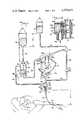
- FIG. 1is a schematic of the fluid flow scheme in a preferred device according to the present invention used to administer medical liquid intravenously to a patient;
- FIG. 2is an enlarged detail view of a valve assembly used in a preferred device utilizing the flow scheme of FIG. 1, said valve assembly used when liquid from a secondary liquid source is to be administered to a patient;
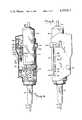
- FIG. 3is a perspective view of the same preferred device utilizing the flow scheme of FIG. 1 whose valve assembly is shown in FIG. 2;
- FIG. 4is a side sectional view of the device taken along line 4--4 of FIG. 3;
- FIG. 5is a view of the device from the side opposite that of FIG. 4;
- FIG. 6is a side sectional view of the device
- FIG. 7is a rear view of the device taken along line 7--7 of FIG. 6;
- FIG. 8is an overhead sectional view of the device similar to that of FIG. 9;
- FIG. 9is an overhead sectional view of the device taken along line 9--9 of FIG. 6;
- FIG. 10is an exploded view of the device, with a detail view (FIG. 10A) showing how the membrane filter is held in place;
- FIG. 11is an enlarged perspective detail view of the back of the device showing the three cannulae used therein in their respective tubing;
- FIG. 12is a side sectional view taken along line 12--12 of FIG. 11.
- FIG. 1is a schematic of a preferred device embodying the present invention.
- the flow rates of primary intravenous fluid from supply 20 and secondary intravenous fluid from supply 22 to needle 26 in patient's arm 24are controlled by the new device.
- primary fluidflows from supply 20 into first chamber 28, into one of three cannulae 46, out of dropping needle 62 in second chamber 62, through membrane valve 66, into third chamber 34, and then to the patient.
- the secondary fluidflows from supply 22 into valve 90 in which the flow is split into two parallel but unequal streams, which are through the cannula 46 that was being used for the primary fluid and through line 96.
- Administration of secondary fluidtemporarily halts the flow of primary fluid; when the secondary supply is exhausted primary flow restarts at its originally set flow rate.
- notch 54is disposed around and does not pinch the flexible tubing for branch 50b, while branches 50a and 50c are pinched shut between the back edge of slide valve 52 and another member (not shown). Accordingly, fluid entering header 108 passes through cannula 46b but not through cannulae 46a or 46c. If slide valve 52 were moved so that notch 54 were around the tubing for branch 50a or 50c, fluid would flow, respectively, through cannula 46a and 46c only.
- the three branchesjoin at collection header 56, from which the fluid flows through tubing 58 into second chamber 32 via inlet 60 having dropping needle 62, from which the fluid falls in the form of drops onto membrane filter 66 at outlet 64.
- Liquidpasses through membrane filter 66 into third chamber 34 via inlet 68 leading to dropping needle 70.
- the liquidleaves third chamber 34 via outlet 72 from a small pool of fluid 162 at the bottom of the chamber and flows through tubing 74 into needle 26 in patient's arm 24.
- Second chamber 32 and third chamber 34are located in the same housing 36 and are separated by membrane valve 66.
- first chamber 28above liquid 76
- second chamber 32which chamber contains essentially only gas
- tubing 88which connects outlets 82 and 84 of the two chambers.
- Priming valve 88 in tubing 86is normally open.
- priming valve 88is closed, slide valve 52 is moved so that all three branches can pass liquid, and primary supply 20 is fluidly connected to tubing 30 so that liquid flows from supply 20 through tubing 30, through inlet 38 and valve 42, and to the bottom of first chamber 28.
- hydrophobic membrane valve 78As air leaves the first chamber through hydrophobic membrane valve 78, the liquid rises past the top of hydrophilic membrane valve 80 and flows through outlet 40 into tubing 48 (hydrophobic valve 78 is higher than hydrophilic valve 80). The liquid then flows into header 108 and through all three branches 50 until the three cannulae 46 are reached. Liquid temporarily stops flowing out of first chamber 28 because the cannulae provide the only significant flow restriction (or pressure drop) from outlet 40 to inlet 60. That is, additional pressure is required to force the liquid through the cannulae. Thus, since the liquid flowing into first chamber 28 from supply 20 cannot leave, the level of liquid 76 starts to rise and the liquid forces additional air out of the first chamber 28 through hydrophobic membrane valve 78. The gas phase pressure has to this point remained essentially at atmospheric.
- first chamber 28starts to pressurize. Pressurization caused by fluid entering from supply 20 continues until the pressure of the gas compressed within first chamber 28 reaches the hydrostatic pressure on the fluid entering (at inlet 38).
- Fluidcontinues to flow at a high rate into first chamber 28 and out needle 26 until slide valve 52 is moved out of the priming position and notch 54 engages the tubing for one of the three branches 50. Then, as described above, liquid flows through only one of the three cannulae 46. Additionally, at the end of the priming procedure valve 88 is opened, allowing the gas pressure in first and second chambers 28 and 32 to equalize.
- the height of liquid in supply 20typically varies from approximately 16 inches (406 mm) for a full 1-liter IV bag down to 0 inches when empty.
- Tubing 30is approximately 6 inches (152 mm) long (dimension A).
- the hydrostatic head on fluid entering at inlet 38is typically between approximately 6 and 22 inches (152 and 559 mm, respectively).
- this difference in headcauses the level of fluid 76 above membrane 78 to vary from 0.125 to 0.185 inches (3.2 to 4.7 mm).
- dimension h(the height of fluid above outlet 40) is approximately 0.375 inches (9.5 mm) and because first chamber 28 is movable vertically with respect to second chamber 32, vertical dimension R (the top of fluid 76 to the end of dropping needle 62) varies from approximately 1.75 to 4.5 inches (45 to 114 mm).
- First and second chambers 28 and 32are gas phase pressure-equalized by tubing 86, thus, a pressure loss equal to hydrostatic head R (1.75 to 4.5 inches--45 to 114 mm--of liquid) is what is available to move the liquid from first chamber 28 to the end of dropping needle 62.
- the deviceis designed so that essentially all of the pressure loss occurs in whichever cannula is selected, that is, the cannula provides the only significant pressure drop in the fluid path from outlet 40 to the end of dropping needle 62. Accordingly, for each cannula, a specific value of R causes a specific predeterminable flow rate of liquid and, therefore, the device can be premarked with indicia at different relative first chamber heights corresponding to those flow rates.
- Those premarked flow rateswill be correct within the accuracy required for liquids not varying significantly in specific gravity or viscosity from that of the liquid used to calibrate and premark the device (e.g., plus or minus 10% in viscosity). For example, if the device is premarked with flow rates for saline solution, having a viscosity at room temperature of about 1 cp, the device may be used with fluids having viscosities up to 1.1 cp without significant error. Of course, the device may be calibrated and premarked for higher viscosity fluids.
- the gas phase pressure in third chamber 34is below atmospheric. It is equal to atmospheric pressure minus the pressure equal to the height of fluid from the top of fluid 162 to the discharge end of needle 26 (dimension H) plus the venous pressure. That typically is equal to a vacuum of approximately 30 inches (762 mm) of liquid (H is approximately 36 inches--914 mm--and venous pressure is typically 5 to 6 inches--127 to 152 mm).
- the gas phase pressure in second chamber 32is above atmospheric and is the same as the gas phase pressure in first chamber 28 or between 6 inches and 22 inches (152 and 559 mm) of liquid gauge.
- the pressure differential drawing liquid that falls from dropping needle 62 onto membrane 66 into third chamber 34is from 36 (6 plus 30) to 52 (22 plus 30) inches (914 to 1321 mm) of liquid. Accordingly, the flow rate of liquid from supply 20 through dropping needle 70 is independent of the patient's raising or lowering the needle's point of entry (assuming it is not raised sufficiently to decrease the driving force on the liquid passing through membrane 66 from second chamber 32 to zero or less).
- the discharge of secondary supply 22is placed at a level higher than the discharge of primary supply 20 (dimension B), typically 9 inches (229 mm) higher.
- Tubing 92 from supply 22is connected to valve assembly 90, and assembly 90 is connected to header 108 and to tubing 58 by tubing 96.
- a small amount of secondary fluidthen flows along tubing 48 to header 108 and forces liquid back into first chamber 28 because of the higher hydrostatic head on liquid leaving supply 22. That raises the level of liquid in first chamber 28, which further pressurizes the gas therein. That, in turn, causes inlet valve member 44 to move up within valve 42 and temporarily halt the flow of primary fluid into first chamber 28. Since priming valve 88 is open, the gas phase pressure in second chamber 32 also rises.
- Secondary fluid forced into header 108also flows through whichever branch 50 was being used to meter the primary fluid.
- the major flow of secondary fluidis through tubing 96.
- the minor flow of secondary fluid through one of the branches 50, cannula 46, header 56, and tubing 58mixes with the major flow through tubing 96.
- the combined flowenters second chamber 32 through inlet 60, flows out of dropping needle 62, out outlet 64, through hydrophilic membrane valve 66, into third chamber 34 through inlet 68, through dropping needle 70, and to the patient through tubing 74 and needle 26.
- the flow rate of secondary fluid out of dropping needle 70 in third chamber 34is adjusted by valve 94.
- secondary fluidis administered at comparatively high flow rates and in volumes less than 100 cc.
- the level of liquid in tubing 92falls, thereby decreasing the gas phase pressure in first chamber 28.
- the liquid in tubing 92falls to a level such that the hydrostatic pressure on primary fluid entering first chamber 28 at inlet 38 is greater than the gas phase pressure.
- valve member 44moves down and the flow of primary fluid into first chamber 28 resumes. Because neither the relative height of the first and second chambers nor slide valve 52 had to be moved to administer secondary fluid, the primary fluid resumes its flow out of first chamber 28 and into the patient at the rate set before administration of the secondary fluid commenced.
- FIG. 2is a detailed view, showing valve assembly 90 in a device embodying the principles of FIG. 1.
- Valve 100 in valve assembly 90comprises three layers: a central compressible foam rubber disc and two matching silicone rubber discs, one on either side of the foam rubber.
- the foam core of valve 100is fully expanded between support ribs 164 of header 108 and valve seat 104. (Upper rib 164 is also shown in FIG. 11.)
- the right silicone rubber disc of valve 100is seated on valve seat 104, thus preventing primary fluid from entering tubing 92 or 96. That ensures that all the primary fluid leaving primary supply 20 and entering header 108 passes through the cannula selected (in FIG. 2, branch 50c and cannula 46c).
- valve assembly 90When secondary fluid flows into valve assembly 90 via tubing 92, the major part of the flow passes directly into tubing 96 and to the patient, as explained above. All of the air in tubing 92 and 96 passes through opening 102 and out of the device through hydrophobic membrane valve 98. The higher hydrostatic head on the secondary liquid to the right of valve 100 pushes the right silicone rubber disc of valve 100 to the left, thereby temporarily compressing the central foam rubber core and allowing secondary fluid to flow through passageway 106 into header 108. As explained above, this minor flow of secondary fluid causes the flow of primary fluid into first chamber 28 to stop temporarily by closing inlet valve 42. Additionally, some of this secondary fluid passing into header 108 flows through whichever cannula was being used for the primary fluid (in this case, cannula 46c).
- FIG. 3is a perspective view of the preferred device containing valve assembly 90 of FIG. 2 and constructed in accordance with the schematic of FIG. 1.
- the slotcomprises three vertical portions, 116a, b, and c, and one horizontal portion, 116d. Because of the configuration of the slot, housing portions 118a and b are connected to the rest of housing 110 at only their bottom ends. Thus, shield 120 (only a portion of which is shown) is provided to prevent excessive outward movement of those portions. Shield 120 is constructed so that arm 168 of button 112 (FIG. 6) is free to slide under it when the button is in slot portion 116d.
- Each slot portion 116a, b, and ccorresponds to selection of one of the three cannulae, as will be described below.
- Button 112 in phantom linecorresponds to selection of branch 50a with cannula 46a.
- button 112is moved up in slot portion 116a, pushed to the right in slot portion 116d, and then pushed down into slot portion 116c to the desired level.
- dropping needle 62 in second chamber 32is held stationary in housing 110 and first chamber 28 is movable vertically within the housing to vary dimension R (FIG. 1), thereby to set the flow rate.
- Indicia 114 to the sides of slot portions 116a, b, and care in milliliters per hour and correspond to the particular cannula and height R chosen.
- FIG. 4is a sectional view of the device taken along line 4--4 of FIG. 3.
- Button 112is connected to lever gear 122 having teeth 124.
- the gearis rotatably connected to the bottom of first chamber 28.
- button 112is pushed up as high as it will go, first chamber 28 is pushed to its highest and teeth 124 mesh with teeth 130 on horseshoe gear 126, which is rotatably mounted on mounts 128 connected to the back wall of housing 110.
- Detent 132rides on the rim of horseshoe gear 126 (see also FIG. 10), which rim has four notches 134. Three notches are positioned to mate with detent 132 when button 112 is in one of the slot portions 116a, b, or c. The fourth notch 134 mates with detent 132 when button 112 is in horizontal slot portion 116d and is moved past the highest flow range, a position denominated "Prime” on housing 110 (see FIG. 5). Detent 132 and the notches cooperate to prevent movement of horseshoe gear 126 when first chamber 28 moves down in housing 110, which unmeshes teeth 124 (on lever gear 122) and teeth 30 (on gear 126).
- Retaining clips 136mounted on the back wall of housing 110, keep horseshoe gear 126 from slipping off of or tilting on mounts 128. Also shown in FIG. 4 are dropping needle 70 in third chamber 34 and tubing 74 connected to outlet 72.
- Tubing 48carries primary liquid from the bottom of first chamber 28 to header 108, mounted on the rear wall of housing 110.
- Tubing 86for gas phase pressure equalization, runs from first chamber 28 to the bottom of housing 110, where second chamber 32 (not shown) and third chamber 34 are located.
- the three branch lines 50(only one of which, 50c, is shown) run from header 108 down to collection header 56 and tubing 58 runs from header 56 to the inlet of the second chamber.
- FIG. 5shows the outside of the device opposite the side of FIG. 4.
- Shield 120which follows slot portion 116d, is shown.
- Button 112is in slot portion 116c, allowing metering of primary flows in the 95 to 250 ml/h range.
- Valve 94allows flow rate control of the secondary fluid.
- FIG. 6is a view of the same side of the device as in FIG. 4 but with the entire device in section.
- Chamber 28has been raised to its highest position by button 112 and teeth 124 and 130 of gears 122 and 126 are meshed.
- Arm 168connects button 112 to lever gear 122.
- Tubing 86which equalizes the gas phase pressures in first and second chambers 28 and 32, runs from gas phase connection (or riser) 82 to gas phase connection 84.
- the liquid level in chamber 28(dimension h in FIG. 1) is only approximately 0.375 inches (9.5 mm) for this device and the riser is approximately 1.4 inches (36 mm) high
- cap 138is provided to prevent liquid entering first chamber 28 via tubing 30 from going into riser 82 and tubing 86. Liquid leaving first chamber 28 passes through hydrophilic membrane valve 80 and outlet 40 before entering tubing 48 (only a portion of which is shown) to go to header 108.
- buttons 112 in slot portion 116cthat is, the device is set for the highest flow range (cannula 46c is selected)
- button 112 in slot portion 116bthat is, the middle flow range (cannula 46b) is selected. Accordingly, as in FIG. 1, branch tubing for the other two cannulae must be pinched so that liquid flowing from header 108 to header 56 passes through cannula 46b only.
- FIG. 6shows how this pinching is accomplished.
- Back rim raised portion 144 of horseshoe gear 126pushes a section of branch tubing 50c against upper and lower compression bars 150a and b, which are mounted on the rear wall of housing 110. That pinches tubing 50c sufficiently to prevent fluid flow through it.
- Another portion of back rim raised portion 144pinches tubing 50a (not shown) with the same result.
- Top and bottom retaining clips 136ensure that back rim raised portion 144 sufficiently pushes tubing 50a and c against compression bars 150.
- Second and third chambers 32 and 34are located in T-shaped housing 36 and are separated by membrane valve 66: above membrane 66 is outlet 64 of second chamber 32 and below membrane 66 is inlet 68 of third chamber 34.
- FIG. 7is a rear view of the device.
- Tubing 48 from the bottom of first chamber 28passes up the right inside of the device to elbow 170, which leads into header 108.
- Branch tubing sections 50a, b, and crun from header 108 to collection header 56 and tubing 58 carries liquid from the latter to second chamber inlet 60.
- Each branch 50has a cannula 46 in it.
- back rim raised portion 144is compressing branch tubing 5a and c against compression bars 150a and b to prevent flow through them.
- the sides of notch 154, centrally located in raised portion 144bracket but do not compress tubing 50b in the region between compression bars 150. That is why tubing 50b is not also compressed by raised portion 144.
- Cannula 46a and bare located close to header 56; cannula 46c is located with its upper end close to the inside top of header 108 to provide a path for air in header 108 to leave when the device is primed.
- the back rim of horseshoe gear 126has raised portion 144 and lower portion 146, with two transition sloped surfaces 148. Shown in this view are the four notches 134 that mate with detent 132 and the end of the detent connected to the rear wall. Also visible are the ends of the two upper retaining clips 136, which are connected to the rear wall.
- Secondary fluid supply 22(not shown) is connected to the device by inserting a needle at the end of connecting tubing 92 (not shown--see FIG. 1) into elastomeric stopple 140.
- the secondary fluidthen flows directly into valve assembly 90.
- the details of the construction and operation of valve assembly 90are described above in connection with FIG. 2.
- the major portion of secondary liquid flowing through valve assembly 90goes into tubing 96, which meets with tubing 58 at header 142 atop second chamber 32 (not shown).
- the minor portion of the flowgoes through tubing 58, and the combined flow at header 142 goes into second chamber 32 through dropping needle 62 (not shown--see FIG. 6).
- Valve 94is a screw-compression type. As valve 94 is turned clockwise to decrease the secondary fluid flow rate, tubing 96 is pinched between the end of the screw and the left end of collection header 56. Counter-clockwise rotation increases the flow rate.
- FIGS. 8 and 9are top sectional views taken along line 9--9 of FIG. 6.
- FIG. 9shows the device in the same configuration as in FIG. 6, that is, set to the middle flow range.
- FIG. 8shows the device set to the lowest flow range.
- teeth 124 of lever gear 122are meshed with teeth 130 of horseshoe gear 126 and branch tubing sections 50a, b, and c are seen to be between gear 126 and upper compression bar 150a (the lower compression bar is not visible).
- button 112is set to the lowest flow range (as shown in phantom line in FIG. 3).
- Tubing 50b and care both clamped shut between back rim raised portion 144 and compression bars 150.
- One of the inclined transition surfaces 148lies next to tubing 50a, which remains open, thereby allowing primary flow through cannula 46a only.
- button 112When button 112 is moved within slot portion 116d (FIG. 3) to the position shown in FIG. 9, gear 122 rotates counter-clockwise causing horseshoe gear 126 to rotate counter-clockwise when viewed from the front. That moves notch 154 around tubing 50b and causes the rest of back rim raised portion 144 to clamp shut branch tubing 50a and c, as in FIG. 9. Button 112 is now positioned over slot portion 116b and may be moved vertically therein.
- FIG. 10is an exploded perspective view of the device showing the front of housing 110 and first chamber 28 broken away from the rear of housing 110 and second and third chambers 32 and 34.
- Valve 42admits primary liquid from tubing 30 into first chamber 28.
- Button 112is in slot portion 116c, that is, the device is set to the highest flow range.
- Shown in phantom lineare hydrophobic membrane valve 78 (which allows air to leave the chamber during priming), hydrophilic membrane valve 80 (through which primary liquid from first chamber 28 passes via tubing 48 to header 108), riser 82 with cap 138 (which riser is connected to second chamber 32 by gas phase pressure equalization tubing 86), and lever gear 122.
- Hydrophilic membrane valve 66separates second and third chambers 32 and 34. Liquid from the latter flows to the patient through tubing 74, which has check valve 156 in the flow path.
- FIG. 10Ashows that membrane 66 is mounted between sidewall 158 and horizontal portion 160 of housing 36.
- FIG. 11is a rear perspective view of horseshoe gear 126, the headers, and associated tubing.
- gear 126has been rotated clockwise (when viewed from the front) as far as possible.
- one part of back rim raised portion 144is compressing tubing 50b and c against compression bars 150a and b, thereby preventing flow through middle and high range cannulae 46b and c, but back rim lower portion 146 is not pinching tubing 50a, thereby allowing flow through low flow range cannula 46a.
- First chamber 28is at its highest and teeth 124 and 130 of lever gear 122 and horseshoe gear 126 are meshed.
- Valve 100lies between ribs 164 and valve assembly 90 and air exit port 102 and hydrophobic membrane valve 98 are visible (see FIG. 2).
- Secondary tubing 96is positioned between the left end of collection header 56 and the end of the screw of valve 94.
- FIG. 12is a sectional view taken along line 12--12 of FIG. 11 and shows that with the horseshoe gear in the position shown in FIG. 11, back rim lower portion 146 does not force branch tubing 50a against compression bars 150a and b. Therefore, tubing 50a remains open and all the liquid flowing from header 108 to collection header 56 must pass through cannula 46a.
- button 112is moved up to slot portion 116d (FIG. 3) and the button is moved to the "Prime” position (FIG. 5). That causes horseshoe gear 126 to rotate counterclockwise (when viewed from the front) as far as possible so that the raised portion 144 of the rear rim does not contact any of the three branches 50. Thus, liquid flows through all three. Also, when button 112 is moved to "Prime,” a tab at the bottom of and on lever gear 122 is brought around to bend over and thereby crimp and close off pressure equalization tubing 86 near where the tubing exits from first chamber 28 (see FIG. 6, although the tab is not shown). Thus, that tab performs the function of valve 88 in FIG. 1.
- First chamber 28is 1.5 inches (38 mm) in diameter by 4.3 inches (109 mm) long (straight-side).
- Housing 110 from its top to the bottom of third chamber 34is 8.6 inches (216 mm) long and 2.5 inches (64 mm) at its widest (not including shield 120). The other dimensions may be determined by consulting FIGS. 4-9 since they are essentially to scale.
- Cannula 46afor the lowest range (10-20 ml/h), is a standard hypodermic cannula of 25 gauge size, 0.75 inches (19 mm) long; cannula 46b (20-65 ml/h), 23 gauge, 0.5 inches (13 mm) long; and cannula 46c (90-250 ml/h), 20 gauge, 1.25 inches (32 mm) long.
- hydrophilic and hydrophobic membranes used hereinshould have sufficiently high break-through pressures and strengths and other satisfactory physical properties so that they can perform in the manner described above.
- hydrophilic membrane valve 66should have a bubble point pressure of at least 5 psi (35 kPa).
- the pore size of membrane 66may vary over a wide range, e.g., from about 0.1 to over 250 microns, smaller sizes providing the additional benefit of particulate filtering.
- the pore size of membrane 80must be large enough so that the pressure drop through it is small compared to that through whichever cannula 46 is being used.
- membrane 66is strong enough so that it can be compression fitted between members 158 and 160 (FIG. 10A) to achieve the desired result without the need for any gaskets. That simplifies fabrication.
- Other means for retaining the membrane in placemay be used, e.g., ultrasonic bonding, which is most preferred.
- the devicemay be made of any pharmacologically acceptable material.
- styrenehas been found to be suitable.
- the tubingmay be of polyvinyl chloride. Whatever the material, the tubing must be resilient enough to recover from any deformation (e.g., when tubing 86 is crimped by the tab on gear 122 during priming).
- Cannulae 46a, b, and c and dropping needles 62 and 70may be of Inconel or type 304 stainless steel.
- the membranesmay be of any suitable materials. Acrylic with a pluronic acid wetting agent has been found to be satisfactory for membrane 66.
- valve 100 and header 108may be arranged so that when secondary liquid flow commences, valve 100 halts the flow of primary liquid from header 108 to the cannula then in use.
- a particulate liquid outlet filtermay be added to the bottom of first chamber 28.
- Such a filterwould need a bubble point of at least 4.5 inches (114 mm) and preferably 9-10 inches (229-254 mm) and a low pressure drop compared to that of high flow range cannula 46c.
- Any means known in the art which ensures a constant liquid head at the inlet of the cannulamay be used.
- first chamber 28could employ an inlet float check valve to maintain the height of liquid therein within narrow limits.
Landscapes
- Health & Medical Sciences (AREA)
- Biomedical Technology (AREA)
- Hematology (AREA)
- Vascular Medicine (AREA)
- Engineering & Computer Science (AREA)
- Anesthesiology (AREA)
- Veterinary Medicine (AREA)
- Heart & Thoracic Surgery (AREA)
- Public Health (AREA)
- Life Sciences & Earth Sciences (AREA)
- Animal Behavior & Ethology (AREA)
- General Health & Medical Sciences (AREA)
- Fluid Mechanics (AREA)
- Physics & Mathematics (AREA)
- Infusion, Injection, And Reservoir Apparatuses (AREA)
Abstract
Description
Claims (14)
Priority Applications (1)
| Application Number | Priority Date | Filing Date | Title |
|---|---|---|---|
| US06/233,095US4375813A (en) | 1981-02-10 | 1981-02-10 | Medical fluid flow rate controlling device |
Applications Claiming Priority (1)
| Application Number | Priority Date | Filing Date | Title |
|---|---|---|---|
| US06/233,095US4375813A (en) | 1981-02-10 | 1981-02-10 | Medical fluid flow rate controlling device |
Publications (1)
| Publication Number | Publication Date |
|---|---|
| US4375813Atrue US4375813A (en) | 1983-03-08 |
Family
ID=22875866
Family Applications (1)
| Application Number | Title | Priority Date | Filing Date |
|---|---|---|---|
| US06/233,095Expired - Fee RelatedUS4375813A (en) | 1981-02-10 | 1981-02-10 | Medical fluid flow rate controlling device |
Country Status (1)
| Country | Link |
|---|---|
| US (1) | US4375813A (en) |
Cited By (27)
| Publication number | Priority date | Publication date | Assignee | Title |
|---|---|---|---|---|
| EP0206195A3 (en)* | 1985-06-21 | 1987-08-19 | Applied Biomedical Corporation | Gravity-independent infusion system |
| US4857048A (en)* | 1987-05-29 | 1989-08-15 | Hewlett-Packard Company | IV pump and disposable flow chamber with flow control |
| US5009251A (en)* | 1988-11-15 | 1991-04-23 | Baxter International, Inc. | Fluid flow control |
| US5014750A (en)* | 1988-03-14 | 1991-05-14 | Baxter International Inc. | Systems having fixed and variable flow rate control mechanisms |
| US5033714A (en)* | 1988-03-14 | 1991-07-23 | Baxter International Inc. | Systems having fixed and variable flow rate control mechanisms |
| US5176360A (en)* | 1988-03-14 | 1993-01-05 | Baxter International Inc. | Infusor having fixed and variable flow rate control mechanisms |
| US5730730A (en)* | 1995-09-29 | 1998-03-24 | Darling, Jr.; Phillip H. | Liquid flow rate control device |
| EP0836859A3 (en)* | 1996-10-15 | 1998-10-07 | Nissho Corporation | Multi stage type flow rate switching device |
| US6213986B1 (en) | 1995-09-29 | 2001-04-10 | Appro Healthcare, Inc. | Liquid flow rate control device |
| WO2001028610A1 (en)* | 1999-10-15 | 2001-04-26 | Baxter International Inc. | Fluid flow rate switching device |
| US6467953B1 (en) | 1999-03-30 | 2002-10-22 | Medical Solutions, Inc. | Method and apparatus for monitoring temperature of intravenously delivered fluids and other medical items |
| US6705173B1 (en) | 2001-09-05 | 2004-03-16 | Autoquip, Inc. | Air flow rate meter |
| US6824528B1 (en) | 1997-03-03 | 2004-11-30 | Medical Solutions, Inc. | Method and apparatus for pressure infusion and temperature control of infused liquids |
| US7041941B2 (en) | 1997-04-07 | 2006-05-09 | Patented Medical Solutions, Llc | Medical item thermal treatment systems and method of monitoring medical items for compliance with prescribed requirements |
| US7090658B2 (en) | 1997-03-03 | 2006-08-15 | Medical Solutions, Inc. | Temperature sensing device for selectively measuring temperature at desired locations along an intravenous fluid line |
| US20060291533A1 (en)* | 1997-04-07 | 2006-12-28 | Faries Durward I Jr | Medical item thermal treatment systems and method of monitoring medical items for compliance with prescribed requirements |
| US20070161952A1 (en)* | 2004-03-09 | 2007-07-12 | Faries Durward I Jr | Method and apparatus for facilitating injection of medication into an intravenous fluid line while maintaining sterility of infused fluids |
| US20080017260A1 (en)* | 2006-07-20 | 2008-01-24 | Seik Oh | Multirate tubing flow restrictor |
| US20080077079A1 (en)* | 2004-12-21 | 2008-03-27 | Bruno Slettenmark | Liquid Dosing Arrangement |
| US20080243057A1 (en)* | 2002-06-21 | 2008-10-02 | Jacobson James D | Fluid delivery system and flow control therefor |
| US20090314352A1 (en)* | 2008-06-19 | 2009-12-24 | Hyun Dongchul D | Variable flow rate controller |
| US7740611B2 (en) | 2005-10-27 | 2010-06-22 | Patented Medical Solutions, Llc | Method and apparatus to indicate prior use of a medical item |
| US8226605B2 (en) | 2001-12-17 | 2012-07-24 | Medical Solutions, Inc. | Method and apparatus for heating solutions within intravenous lines to desired temperatures during infusion |
| US8226293B2 (en) | 2007-02-22 | 2012-07-24 | Medical Solutions, Inc. | Method and apparatus for measurement and control of temperature for infused liquids |
| US9119912B2 (en) | 2001-03-12 | 2015-09-01 | Medical Solutions, Inc. | Method and apparatus for controlling pressurized infusion and temperature of infused liquids |
| US9211381B2 (en) | 2012-01-20 | 2015-12-15 | Medical Solutions, Inc. | Method and apparatus for controlling temperature of medical liquids |
| US9656029B2 (en) | 2013-02-15 | 2017-05-23 | Medical Solutions, Inc. | Plural medical item warming system and method for warming a plurality of medical items to desired temperatures |
Citations (69)
| Publication number | Priority date | Publication date | Assignee | Title |
|---|---|---|---|---|
| US1205410A (en)* | 1914-01-07 | 1916-11-21 | Alonzo C Tenney | Injection apparatus. |
| US1338782A (en)* | 1917-06-04 | 1920-05-04 | Icy Hot Bottle Company | Coating apparatus and method of coating |
| US1427455A (en)* | 1920-04-28 | 1922-08-29 | Major E Gates | Fluid-controlling device |
| US1844342A (en)* | 1930-04-21 | 1932-02-09 | Berman Phoebus | Bottle nozzle |
| US2090273A (en)* | 1933-10-20 | 1937-08-17 | Roy L Wagner | Embalming device |
| US2254833A (en)* | 1940-06-27 | 1941-09-02 | John Wyeth And Brother Inc | Method and apparatus for controlling intermittent fluid flow |
| US2479786A (en)* | 1945-10-24 | 1949-08-23 | Daniel S Stevens | Liquid flow gauge |
| US2865534A (en)* | 1956-12-17 | 1958-12-23 | Coca Cola Co | Device to maintain a constant liquid level in a container |
| GB817387A (en)* | 1954-11-05 | 1959-07-29 | Reginald Frank Fletcher | Improvements in drip-feed dispensing devices |
| US2954028A (en)* | 1955-10-26 | 1960-09-27 | Russell C Smith | Apparatus for administering parenteral fluids |
| US2971366A (en)* | 1957-09-27 | 1961-02-14 | Dearborn Gage Company | Gage calibration device |
| US2989052A (en)* | 1957-09-12 | 1961-06-20 | Baxter Laboratories Inc | Parenteral fluid equipment |
| US3001397A (en)* | 1958-01-29 | 1961-09-26 | Joe H Leonard | Method and apparatus for measuring liquid flow-volume |
| US3017885A (en)* | 1959-03-30 | 1962-01-23 | Robicsek Francis | Blood flow meter |
| US3034504A (en)* | 1958-11-21 | 1962-05-15 | Galasyn Inc | Flow meter for an intravenous injection unit |
| US3037384A (en)* | 1959-11-06 | 1962-06-05 | Information Systems Inc | Multi-range fluid flow measuring apparatus |
| US3049918A (en)* | 1960-03-11 | 1962-08-21 | Theodore Gregory | Fluid flowmeters |
| US3101710A (en)* | 1960-06-08 | 1963-08-27 | Wilbur R Koehn | Injection set and flow meter for parenteral fluids |
| US3157481A (en)* | 1961-12-11 | 1964-11-17 | Abbott Lab | Air filter assembly |
| US3166107A (en)* | 1963-01-23 | 1965-01-19 | Gerber Prod | Apparatus for serially filling containers |
| US3198009A (en)* | 1958-07-22 | 1965-08-03 | Flotron Inc | Mass flowmeter |
| US3207372A (en)* | 1962-09-21 | 1965-09-21 | Sterilon Corp | Intravenous feeding apparatus |
| US3216418A (en)* | 1962-06-01 | 1965-11-09 | Abbott Lab | Apparatus for administering parenteral solutions |
| US3227173A (en)* | 1963-06-19 | 1966-01-04 | Bernstein Jacob | Valve for parenteral liquid feed apparatus |
| US3241365A (en)* | 1963-03-12 | 1966-03-22 | Schroeder Brothers | Flow gauge |
| US3277708A (en)* | 1963-09-06 | 1966-10-11 | Sundstrand Corp | Flow control device |
| US3298367A (en)* | 1964-01-10 | 1967-01-17 | Richard I Bergman | Apparatus for administering parenteral liquids |
| US3299904A (en)* | 1964-04-23 | 1967-01-24 | Burron Medical Prod Inc | Tube compressor having incremental steps of flow adjustment |
| US3316935A (en)* | 1964-06-24 | 1967-05-02 | Abbott Lab | Flow control clamp |
| US3321970A (en)* | 1964-10-15 | 1967-05-30 | Charles Wheatley Company | Dual orifice plug fitting |
| US3340871A (en)* | 1965-10-22 | 1967-09-12 | Baxter Don Inc | Parenteral liquid administration apparatus |
| US3450164A (en)* | 1966-05-12 | 1969-06-17 | Wheatley Co Charles | Dual orifice plug fitting |
| US3460526A (en)* | 1965-08-23 | 1969-08-12 | Horizon Ind Ltd | Apparatus for flow-control and pressure measurement |
| US3487808A (en)* | 1967-09-06 | 1970-01-06 | Rolls Royce | Devices for indicating the flow of a liquid through a pipe |
| GB1182016A (en)* | 1967-02-08 | 1970-02-25 | Baxter Laboratories Inc | Parenteral Administration of Liquids |
| US3498316A (en)* | 1968-04-08 | 1970-03-03 | Hoover Co | Positive position pinch valve |
| US3550619A (en)* | 1968-06-21 | 1970-12-29 | Becton Dickinson Co | Tubing holder |
| US3604420A (en)* | 1969-01-21 | 1971-09-14 | Bard Inc C R | Closed system drainage design |
| US3605496A (en)* | 1969-11-10 | 1971-09-20 | Plastic Products Ltd | Flow rate gauges |
| US3626938A (en)* | 1970-06-30 | 1971-12-14 | Antonio A Versaci | Hemodialysis shunt valve device with body connecting means |
| US3667464A (en)* | 1970-09-04 | 1972-06-06 | Lawrence M Alligood Jr | Fluid dispensing device |
| US3677248A (en)* | 1970-08-27 | 1972-07-18 | American Hospital Supply Corp | Surgical irrigation apparatus and method of using same |
| US3690318A (en)* | 1970-04-16 | 1972-09-12 | Bourns Inc | Apparatus for parenteral fluid infusion provided with variable flow control means |
| US3756233A (en)* | 1971-03-31 | 1973-09-04 | M Goldowsky | Liquid administration apparatus |
| US3759098A (en)* | 1972-01-27 | 1973-09-18 | Aeronca Inc | Apparatus for determining fluid flow in a conduit |
| US3785378A (en)* | 1972-04-06 | 1974-01-15 | C Stewart | Flow control valve for intravenous fluids |
| US3796245A (en)* | 1973-11-21 | 1974-03-12 | O Wildensteiner | Drip meters |
| US3803914A (en)* | 1972-06-09 | 1974-04-16 | Surgical Corp | Flow meter for parenteral solutions |
| US3805612A (en)* | 1971-02-08 | 1974-04-23 | Oval Eng Co Ltd | Orifice flow meter |
| US3807397A (en)* | 1972-09-28 | 1974-04-30 | States Surgical Corp | Double drip chamber for intravenous sytems |
| US3826137A (en)* | 1971-06-02 | 1974-07-30 | E Clarke | Method for measuring the rate of flows of liquids |
| US3838599A (en)* | 1972-12-13 | 1974-10-01 | Tri Matic | Flow meter |
| US3851668A (en)* | 1973-07-27 | 1974-12-03 | Medical Environment Devices In | Flow control device |
| US3851526A (en)* | 1973-04-09 | 1974-12-03 | Tylan Corp | Fluid flowmeter |
| US3931818A (en)* | 1974-07-22 | 1976-01-13 | Michael Goldowsky | Liquid administration apparatus |
| US3938539A (en)* | 1973-06-15 | 1976-02-17 | Lennart Strouth | Apparatus for leading off air in connection with the measuring of the flow of a liquid |
| US3941126A (en)* | 1974-08-08 | 1976-03-02 | Dietrich Joseph W | Apparatus for long term intravenous administration of diluted incompatible multiple medications |
| US3949745A (en)* | 1975-08-28 | 1976-04-13 | Howell William L | Parenteral fluid administration set |
| US3963024A (en)* | 1975-04-08 | 1976-06-15 | Michael Goldowsky | Fluid flow regulator |
| US3967620A (en)* | 1974-09-10 | 1976-07-06 | United States Surgical Corporation | Volume limiting chamber |
| US3998097A (en)* | 1975-03-17 | 1976-12-21 | Mitsubishi Jukogyo Kabushiki Kaisha | Flow-measuring device |
| US4043332A (en)* | 1975-05-14 | 1977-08-23 | Nathan Blumberg | Constant flow rate liquid medicament administering device |
| US4056100A (en)* | 1974-09-10 | 1977-11-01 | United States Surgical Corporation | Volume limiting chamber |
| US4079737A (en)* | 1975-01-14 | 1978-03-21 | Med-Pak Corporation | Control valve for infusion system |
| US4099527A (en)* | 1976-04-08 | 1978-07-11 | Howell William L | Parenteral fluid administration sets |
| US4136692A (en)* | 1976-02-19 | 1979-01-30 | Michael Goldowsky | Flow meter administration device |
| US4136693A (en)* | 1977-05-10 | 1979-01-30 | Johnson & Johnson | Constant flow I.V. device |
| US4223695A (en)* | 1979-02-28 | 1980-09-23 | Abbott Laboratories | Novel valve employing hydrophobic and hydrophilic membranes |
| US4256103A (en)* | 1978-10-11 | 1981-03-17 | James Paxinos | Automatic sequential fluid flow apparatus |
- 1981
- 1981-02-10USUS06/233,095patent/US4375813A/ennot_activeExpired - Fee Related
Patent Citations (69)
| Publication number | Priority date | Publication date | Assignee | Title |
|---|---|---|---|---|
| US1205410A (en)* | 1914-01-07 | 1916-11-21 | Alonzo C Tenney | Injection apparatus. |
| US1338782A (en)* | 1917-06-04 | 1920-05-04 | Icy Hot Bottle Company | Coating apparatus and method of coating |
| US1427455A (en)* | 1920-04-28 | 1922-08-29 | Major E Gates | Fluid-controlling device |
| US1844342A (en)* | 1930-04-21 | 1932-02-09 | Berman Phoebus | Bottle nozzle |
| US2090273A (en)* | 1933-10-20 | 1937-08-17 | Roy L Wagner | Embalming device |
| US2254833A (en)* | 1940-06-27 | 1941-09-02 | John Wyeth And Brother Inc | Method and apparatus for controlling intermittent fluid flow |
| US2479786A (en)* | 1945-10-24 | 1949-08-23 | Daniel S Stevens | Liquid flow gauge |
| GB817387A (en)* | 1954-11-05 | 1959-07-29 | Reginald Frank Fletcher | Improvements in drip-feed dispensing devices |
| US2954028A (en)* | 1955-10-26 | 1960-09-27 | Russell C Smith | Apparatus for administering parenteral fluids |
| US2865534A (en)* | 1956-12-17 | 1958-12-23 | Coca Cola Co | Device to maintain a constant liquid level in a container |
| US2989052A (en)* | 1957-09-12 | 1961-06-20 | Baxter Laboratories Inc | Parenteral fluid equipment |
| US2971366A (en)* | 1957-09-27 | 1961-02-14 | Dearborn Gage Company | Gage calibration device |
| US3001397A (en)* | 1958-01-29 | 1961-09-26 | Joe H Leonard | Method and apparatus for measuring liquid flow-volume |
| US3198009A (en)* | 1958-07-22 | 1965-08-03 | Flotron Inc | Mass flowmeter |
| US3034504A (en)* | 1958-11-21 | 1962-05-15 | Galasyn Inc | Flow meter for an intravenous injection unit |
| US3017885A (en)* | 1959-03-30 | 1962-01-23 | Robicsek Francis | Blood flow meter |
| US3037384A (en)* | 1959-11-06 | 1962-06-05 | Information Systems Inc | Multi-range fluid flow measuring apparatus |
| US3049918A (en)* | 1960-03-11 | 1962-08-21 | Theodore Gregory | Fluid flowmeters |
| US3101710A (en)* | 1960-06-08 | 1963-08-27 | Wilbur R Koehn | Injection set and flow meter for parenteral fluids |
| US3157481A (en)* | 1961-12-11 | 1964-11-17 | Abbott Lab | Air filter assembly |
| US3216418A (en)* | 1962-06-01 | 1965-11-09 | Abbott Lab | Apparatus for administering parenteral solutions |
| US3207372A (en)* | 1962-09-21 | 1965-09-21 | Sterilon Corp | Intravenous feeding apparatus |
| US3166107A (en)* | 1963-01-23 | 1965-01-19 | Gerber Prod | Apparatus for serially filling containers |
| US3241365A (en)* | 1963-03-12 | 1966-03-22 | Schroeder Brothers | Flow gauge |
| US3227173A (en)* | 1963-06-19 | 1966-01-04 | Bernstein Jacob | Valve for parenteral liquid feed apparatus |
| US3277708A (en)* | 1963-09-06 | 1966-10-11 | Sundstrand Corp | Flow control device |
| US3298367A (en)* | 1964-01-10 | 1967-01-17 | Richard I Bergman | Apparatus for administering parenteral liquids |
| US3299904A (en)* | 1964-04-23 | 1967-01-24 | Burron Medical Prod Inc | Tube compressor having incremental steps of flow adjustment |
| US3316935A (en)* | 1964-06-24 | 1967-05-02 | Abbott Lab | Flow control clamp |
| US3321970A (en)* | 1964-10-15 | 1967-05-30 | Charles Wheatley Company | Dual orifice plug fitting |
| US3460526A (en)* | 1965-08-23 | 1969-08-12 | Horizon Ind Ltd | Apparatus for flow-control and pressure measurement |
| US3340871A (en)* | 1965-10-22 | 1967-09-12 | Baxter Don Inc | Parenteral liquid administration apparatus |
| US3450164A (en)* | 1966-05-12 | 1969-06-17 | Wheatley Co Charles | Dual orifice plug fitting |
| GB1182016A (en)* | 1967-02-08 | 1970-02-25 | Baxter Laboratories Inc | Parenteral Administration of Liquids |
| US3487808A (en)* | 1967-09-06 | 1970-01-06 | Rolls Royce | Devices for indicating the flow of a liquid through a pipe |
| US3498316A (en)* | 1968-04-08 | 1970-03-03 | Hoover Co | Positive position pinch valve |
| US3550619A (en)* | 1968-06-21 | 1970-12-29 | Becton Dickinson Co | Tubing holder |
| US3604420A (en)* | 1969-01-21 | 1971-09-14 | Bard Inc C R | Closed system drainage design |
| US3605496A (en)* | 1969-11-10 | 1971-09-20 | Plastic Products Ltd | Flow rate gauges |
| US3690318A (en)* | 1970-04-16 | 1972-09-12 | Bourns Inc | Apparatus for parenteral fluid infusion provided with variable flow control means |
| US3626938A (en)* | 1970-06-30 | 1971-12-14 | Antonio A Versaci | Hemodialysis shunt valve device with body connecting means |
| US3677248A (en)* | 1970-08-27 | 1972-07-18 | American Hospital Supply Corp | Surgical irrigation apparatus and method of using same |
| US3667464A (en)* | 1970-09-04 | 1972-06-06 | Lawrence M Alligood Jr | Fluid dispensing device |
| US3805612A (en)* | 1971-02-08 | 1974-04-23 | Oval Eng Co Ltd | Orifice flow meter |
| US3756233A (en)* | 1971-03-31 | 1973-09-04 | M Goldowsky | Liquid administration apparatus |
| US3826137A (en)* | 1971-06-02 | 1974-07-30 | E Clarke | Method for measuring the rate of flows of liquids |
| US3759098A (en)* | 1972-01-27 | 1973-09-18 | Aeronca Inc | Apparatus for determining fluid flow in a conduit |
| US3785378A (en)* | 1972-04-06 | 1974-01-15 | C Stewart | Flow control valve for intravenous fluids |
| US3803914A (en)* | 1972-06-09 | 1974-04-16 | Surgical Corp | Flow meter for parenteral solutions |
| US3807397A (en)* | 1972-09-28 | 1974-04-30 | States Surgical Corp | Double drip chamber for intravenous sytems |
| US3838599A (en)* | 1972-12-13 | 1974-10-01 | Tri Matic | Flow meter |
| US3851526A (en)* | 1973-04-09 | 1974-12-03 | Tylan Corp | Fluid flowmeter |
| US3938539A (en)* | 1973-06-15 | 1976-02-17 | Lennart Strouth | Apparatus for leading off air in connection with the measuring of the flow of a liquid |
| US3851668A (en)* | 1973-07-27 | 1974-12-03 | Medical Environment Devices In | Flow control device |
| US3796245A (en)* | 1973-11-21 | 1974-03-12 | O Wildensteiner | Drip meters |
| US3931818A (en)* | 1974-07-22 | 1976-01-13 | Michael Goldowsky | Liquid administration apparatus |
| US3941126A (en)* | 1974-08-08 | 1976-03-02 | Dietrich Joseph W | Apparatus for long term intravenous administration of diluted incompatible multiple medications |
| US3967620A (en)* | 1974-09-10 | 1976-07-06 | United States Surgical Corporation | Volume limiting chamber |
| US4056100A (en)* | 1974-09-10 | 1977-11-01 | United States Surgical Corporation | Volume limiting chamber |
| US4079737A (en)* | 1975-01-14 | 1978-03-21 | Med-Pak Corporation | Control valve for infusion system |
| US3998097A (en)* | 1975-03-17 | 1976-12-21 | Mitsubishi Jukogyo Kabushiki Kaisha | Flow-measuring device |
| US3963024A (en)* | 1975-04-08 | 1976-06-15 | Michael Goldowsky | Fluid flow regulator |
| US4043332A (en)* | 1975-05-14 | 1977-08-23 | Nathan Blumberg | Constant flow rate liquid medicament administering device |
| US3949745A (en)* | 1975-08-28 | 1976-04-13 | Howell William L | Parenteral fluid administration set |
| US4136692A (en)* | 1976-02-19 | 1979-01-30 | Michael Goldowsky | Flow meter administration device |
| US4099527A (en)* | 1976-04-08 | 1978-07-11 | Howell William L | Parenteral fluid administration sets |
| US4136693A (en)* | 1977-05-10 | 1979-01-30 | Johnson & Johnson | Constant flow I.V. device |
| US4256103A (en)* | 1978-10-11 | 1981-03-17 | James Paxinos | Automatic sequential fluid flow apparatus |
| US4223695A (en)* | 1979-02-28 | 1980-09-23 | Abbott Laboratories | Novel valve employing hydrophobic and hydrophilic membranes |
Cited By (57)
| Publication number | Priority date | Publication date | Assignee | Title |
|---|---|---|---|---|
| EP0206195A3 (en)* | 1985-06-21 | 1987-08-19 | Applied Biomedical Corporation | Gravity-independent infusion system |
| US4857048A (en)* | 1987-05-29 | 1989-08-15 | Hewlett-Packard Company | IV pump and disposable flow chamber with flow control |
| US5014750A (en)* | 1988-03-14 | 1991-05-14 | Baxter International Inc. | Systems having fixed and variable flow rate control mechanisms |
| US5033714A (en)* | 1988-03-14 | 1991-07-23 | Baxter International Inc. | Systems having fixed and variable flow rate control mechanisms |
| US5176360A (en)* | 1988-03-14 | 1993-01-05 | Baxter International Inc. | Infusor having fixed and variable flow rate control mechanisms |
| US5009251A (en)* | 1988-11-15 | 1991-04-23 | Baxter International, Inc. | Fluid flow control |
| US6213986B1 (en) | 1995-09-29 | 2001-04-10 | Appro Healthcare, Inc. | Liquid flow rate control device |
| US5730730A (en)* | 1995-09-29 | 1998-03-24 | Darling, Jr.; Phillip H. | Liquid flow rate control device |
| EP0836859A3 (en)* | 1996-10-15 | 1998-10-07 | Nissho Corporation | Multi stage type flow rate switching device |
| US20050070845A1 (en)* | 1997-03-03 | 2005-03-31 | Faries Durward I. | Method and apparatus for pressure infusion and temperature control of infused liquids |
| US8313462B2 (en) | 1997-03-03 | 2012-11-20 | Medical Solutions, Inc. | Method and apparatus for pressure infusion and temperature control of infused liquids |
| US7540864B2 (en) | 1997-03-03 | 2009-06-02 | Medical Solutions, Inc. | Temperature sensing device for selectively measuring temperature at desired locations along an intravenous fluid line |
| US8920387B2 (en) | 1997-03-03 | 2014-12-30 | Medical Solutions, Inc. | Method and apparatus for pressure infusion and temperature control of infused liquids |
| US7942851B2 (en) | 1997-03-03 | 2011-05-17 | Medical Solutions, Inc. | Method and apparatus for pressure infusion and temperature control of infused liquids |
| US7090658B2 (en) | 1997-03-03 | 2006-08-15 | Medical Solutions, Inc. | Temperature sensing device for selectively measuring temperature at desired locations along an intravenous fluid line |
| US6824528B1 (en) | 1997-03-03 | 2004-11-30 | Medical Solutions, Inc. | Method and apparatus for pressure infusion and temperature control of infused liquids |
| US7276675B2 (en) | 1997-04-07 | 2007-10-02 | Patented Medical Solutions, Llc | Medical item thermal treatment systems and method of monitoring medical items for compliance with prescribed requirements |
| US7307245B2 (en) | 1997-04-07 | 2007-12-11 | Patented Medical Solutions, Llc | Medical item thermal treatment systems and method of monitoring medical items for compliance with prescribed requirements |
| US7041941B2 (en) | 1997-04-07 | 2006-05-09 | Patented Medical Solutions, Llc | Medical item thermal treatment systems and method of monitoring medical items for compliance with prescribed requirements |
| US7417205B2 (en) | 1997-04-07 | 2008-08-26 | Patented Medical Solutions, Llc | Medical item thermal treatment systems and method of monitoring medical items for compliance with prescribed requirements |
| US20060291533A1 (en)* | 1997-04-07 | 2006-12-28 | Faries Durward I Jr | Medical item thermal treatment systems and method of monitoring medical items for compliance with prescribed requirements |
| US20070000910A1 (en)* | 1997-04-07 | 2007-01-04 | Faries Durward I Jr | Medical item thermal treatment systems and method of monitoring medical items for compliance with prescribed requirements |
| US20070015975A1 (en)* | 1997-04-07 | 2007-01-18 | Faries Durward I Jr | Medical item thermal treatment systems and method of monitoring medical items for compliance with prescribed requirements |
| US20040240520A1 (en)* | 1999-03-30 | 2004-12-02 | Faries Durward I. | Method and apparatus for monitoring temperature of intravenously delivered fluids and other medical items |
| US6566631B2 (en) | 1999-03-30 | 2003-05-20 | Medical Solutions, Inc. | Method and apparatus for monitoring temperature of intravenously delivered fluids and other medical items |
| US6722782B2 (en) | 1999-03-30 | 2004-04-20 | Medical Solutions, Inc. | Method and apparatus for monitoring temperature of intravenously delivered fluids and other medical items |
| US6467953B1 (en) | 1999-03-30 | 2002-10-22 | Medical Solutions, Inc. | Method and apparatus for monitoring temperature of intravenously delivered fluids and other medical items |
| US8821011B2 (en) | 1999-03-30 | 2014-09-02 | Medical Solutions, Inc. | Method and apparatus for monitoring temperature of intravenously delivered fluids and other medical items |
| US6273133B1 (en) | 1999-10-15 | 2001-08-14 | Baxter International Inc. | Fluid flow rate switching device |
| WO2001028610A1 (en)* | 1999-10-15 | 2001-04-26 | Baxter International Inc. | Fluid flow rate switching device |
| US9119912B2 (en) | 2001-03-12 | 2015-09-01 | Medical Solutions, Inc. | Method and apparatus for controlling pressurized infusion and temperature of infused liquids |
| US6705173B1 (en) | 2001-09-05 | 2004-03-16 | Autoquip, Inc. | Air flow rate meter |
| US9492624B2 (en) | 2001-12-17 | 2016-11-15 | Medical Solutions, Inc. | Method and apparatus for heating solutions within intravenous lines to desired temperatures during infusion |
| US8920372B2 (en) | 2001-12-17 | 2014-12-30 | Medical Solutions, Inc. | Method and apparatus for heating solutions within intravenous lines to desired temperatures during infusion |
| US8226605B2 (en) | 2001-12-17 | 2012-07-24 | Medical Solutions, Inc. | Method and apparatus for heating solutions within intravenous lines to desired temperatures during infusion |
| US20080243057A1 (en)* | 2002-06-21 | 2008-10-02 | Jacobson James D | Fluid delivery system and flow control therefor |
| US8672876B2 (en) | 2002-06-21 | 2014-03-18 | Baxter International Inc. | Fluid delivery system and flow control therefor |
| US20080255502A1 (en)* | 2002-06-21 | 2008-10-16 | Jacobson James D | Fluid delivery system and flow control therefor |
| US8226597B2 (en) | 2002-06-21 | 2012-07-24 | Baxter International, Inc. | Fluid delivery system and flow control therefor |
| US8231566B2 (en) | 2002-06-21 | 2012-07-31 | Baxter International, Inc. | Fluid delivery system and flow control therefor |
| US20070161952A1 (en)* | 2004-03-09 | 2007-07-12 | Faries Durward I Jr | Method and apparatus for facilitating injection of medication into an intravenous fluid line while maintaining sterility of infused fluids |
| US8845586B2 (en) | 2004-03-09 | 2014-09-30 | Patented Medical Solutions Llc | Method and apparatus for facilitating injection of medication into an intravenous fluid line while maintaining sterility of infused fluids |
| US7611504B1 (en) | 2004-03-09 | 2009-11-03 | Patented Medical Solutions Llc | Method and apparatus for facilitating injection of medication into an intravenous fluid line while maintaining sterility of infused fluids |
| US20080077079A1 (en)* | 2004-12-21 | 2008-03-27 | Bruno Slettenmark | Liquid Dosing Arrangement |
| US8636691B2 (en) | 2005-10-27 | 2014-01-28 | Patented Medical Solutions, Llc | Method and apparatus to indicate prior use of a medical item |
| US8444599B2 (en) | 2005-10-27 | 2013-05-21 | Patented Medical Solutions, Llc | Method and apparatus to indicate prior use of a medical item |
| US7740611B2 (en) | 2005-10-27 | 2010-06-22 | Patented Medical Solutions, Llc | Method and apparatus to indicate prior use of a medical item |
| US20100154909A1 (en)* | 2006-07-20 | 2010-06-24 | Baxter International Inc. | Multirate tubing flow control valve |
| US7690396B2 (en) | 2006-07-20 | 2010-04-06 | Baxter International Inc. | Multirate tubing flow restrictor |
| US20080017260A1 (en)* | 2006-07-20 | 2008-01-24 | Seik Oh | Multirate tubing flow restrictor |
| US7802589B2 (en) | 2006-07-20 | 2010-09-28 | Baxter International Inc. | Multirate tubing flow control valve |
| US8226293B2 (en) | 2007-02-22 | 2012-07-24 | Medical Solutions, Inc. | Method and apparatus for measurement and control of temperature for infused liquids |
| US20090314352A1 (en)* | 2008-06-19 | 2009-12-24 | Hyun Dongchul D | Variable flow rate controller |
| US8118061B2 (en)* | 2008-06-19 | 2012-02-21 | Acacia, Inc. | Variable flow rate controller |
| US9211381B2 (en) | 2012-01-20 | 2015-12-15 | Medical Solutions, Inc. | Method and apparatus for controlling temperature of medical liquids |
| US9764100B2 (en) | 2012-01-20 | 2017-09-19 | Medical Solutions, Inc. | Method and apparatus for controlling temperature of medical liquids |
| US9656029B2 (en) | 2013-02-15 | 2017-05-23 | Medical Solutions, Inc. | Plural medical item warming system and method for warming a plurality of medical items to desired temperatures |
Similar Documents
| Publication | Publication Date | Title |
|---|---|---|
| US4375813A (en) | Medical fluid flow rate controlling device | |
| US4256104A (en) | Equipment sets and system for the sequential administration of medical liquids at dual flow rates | |
| US4324238A (en) | Equipment sets having a combined air barrier and liquid sequencing device for the sequential administration of medical liquids at dual flow rates | |
| US4316460A (en) | Gravitational flow system for the sequential administration of medical liquids | |
| US4451255A (en) | Dual flow rate intravenous administration set with single pump chamber | |
| US4391598A (en) | Intravenous drug additive delivery system with electronic control | |
| US4142523A (en) | Flow control device for the intravenous administration of liquids | |
| US4941875A (en) | I.V. system for successive administration of two or more solutions at different rates | |
| US4173222A (en) | Apparatus for controllably administering a parenteral fluid | |
| EP0102748B1 (en) | Parenteral solution administration set | |
| US8251953B2 (en) | System and method for drug preparation and delivery | |
| US4534764A (en) | Sequential medication delivery device | |
| US4842584A (en) | Disposable fluid infusion pumping chamber cassette and drive mechanism thereof | |
| US4223695A (en) | Novel valve employing hydrophobic and hydrophilic membranes | |
| EP0089404A1 (en) | Gravitational flow system for the sequential administration of a plurality of medical liquids | |
| US3844283A (en) | Apparatus for aseptically dispensing a measured volume of liquid | |
| US6105442A (en) | Fluid delivery apparatus with reservoir fill assembly | |
| EP3019214B1 (en) | Check valve system | |
| JPH0445184B2 (en) | ||
| CA2534772A1 (en) | Infusion apparatus with constant force spring energy source | |
| US4252116A (en) | Equipment sets having a novel flexible diaphragm valve in a secondary liquid flow path for the sequential administration of medical liquids at dual flow rates | |
| US4256105A (en) | Equipment sets having reduced diameter primary tube for the sequential administration of medical liquids at dual flow rates | |
| US4262668A (en) | Fixed volume infusion device | |
| US4340050A (en) | Medical fluid flow rate indicating/controlling device | |
| US4258712A (en) | Equipment sets having a pilot liquid controlled primary tube valve for the sequential administration of medical liquids at dual flow rates |
Legal Events
| Date | Code | Title | Description |
|---|---|---|---|
| AS | Assignment | Owner name:UNITED STATES SURGICAL CORPORATION, 150 GLOVER AVE Free format text:ASSIGNMENT OF ASSIGNORS INTEREST.;ASSIGNOR:HESSEL STEPHEN R.;REEL/FRAME:003867/0628 Effective date:19810205 | |
| AS | Assignment | Owner name:DELMED INC., CANTON, MA. A CORP. OF MA. Free format text:ASSIGNMENT OF ASSIGNORS INTEREST.;ASSIGNOR:UNITED STATES SURGICAL CORPORATION;REEL/FRAME:003991/0038 Effective date:19820521 | |
| AS | Assignment | Owner name:UNITED STATES SURGICAL CORPORATION, A NY CORP. Free format text:SECURITY INTEREST;ASSIGNOR:DELMED, INC. A CORP. OF MA;REEL/FRAME:004005/0779 Effective date:19820527 | |
| CC | Certificate of correction | ||
| AS | Assignment | Owner name:DELMED, INC., A MA CORP Free format text:ASSIGNMENT OF ASSIGNORS INTEREST.;ASSIGNOR:UNITED STATES SURGICAL CORPORATION A NY CORP;REEL/FRAME:004411/0890 Effective date:19830106 | |
| AS | Assignment | Owner name:MANUFACTURRS HANOVER TRUST COMPANY, AS AGENT Free format text:SECURITY INTEREST;ASSIGNOR:DELMED, INC.;REEL/FRAME:004433/0232 Effective date:19850327 | |
| FEPP | Fee payment procedure | Free format text:MAINTENANCE FEE REMINDER MAILED (ORIGINAL EVENT CODE: REM.); ENTITY STATUS OF PATENT OWNER: LARGE ENTITY | |
| LAPS | Lapse for failure to pay maintenance fees | ||
| STCH | Information on status: patent discontinuation | Free format text:PATENT EXPIRED DUE TO NONPAYMENT OF MAINTENANCE FEES UNDER 37 CFR 1.362 | |
| FP | Lapsed due to failure to pay maintenance fee | Effective date:19870308 |