US4374457A - Method of fabricating complex micro-circuit boards and substrates - Google Patents
Method of fabricating complex micro-circuit boards and substratesDownload PDFInfo
- Publication number
- US4374457A US4374457AUS06/174,929US17492980AUS4374457AUS 4374457 AUS4374457 AUS 4374457AUS 17492980 AUS17492980 AUS 17492980AUS 4374457 AUS4374457 AUS 4374457A
- Authority
- US
- United States
- Prior art keywords
- conductive material
- set forth
- electrically conductive
- placing
- grooves
- Prior art date
- Legal status (The legal status is an assumption and is not a legal conclusion. Google has not performed a legal analysis and makes no representation as to the accuracy of the status listed.)
- Expired - Lifetime
Links
Images
Classifications
- H—ELECTRICITY
- H01—ELECTRIC ELEMENTS
- H01L—SEMICONDUCTOR DEVICES NOT COVERED BY CLASS H10
- H01L24/00—Arrangements for connecting or disconnecting semiconductor or solid-state bodies; Methods or apparatus related thereto
- H01L24/01—Means for bonding being attached to, or being formed on, the surface to be connected, e.g. chip-to-package, die-attach, "first-level" interconnects; Manufacturing methods related thereto
- H01L24/42—Wire connectors; Manufacturing methods related thereto
- H01L24/47—Structure, shape, material or disposition of the wire connectors after the connecting process
- H01L24/48—Structure, shape, material or disposition of the wire connectors after the connecting process of an individual wire connector
- H—ELECTRICITY
- H01—ELECTRIC ELEMENTS
- H01L—SEMICONDUCTOR DEVICES NOT COVERED BY CLASS H10
- H01L23/00—Details of semiconductor or other solid state devices
- H01L23/12—Mountings, e.g. non-detachable insulating substrates
- H01L23/13—Mountings, e.g. non-detachable insulating substrates characterised by the shape
- H—ELECTRICITY
- H01—ELECTRIC ELEMENTS
- H01L—SEMICONDUCTOR DEVICES NOT COVERED BY CLASS H10
- H01L23/00—Details of semiconductor or other solid state devices
- H01L23/34—Arrangements for cooling, heating, ventilating or temperature compensation ; Temperature sensing arrangements
- H01L23/36—Selection of materials, or shaping, to facilitate cooling or heating, e.g. heatsinks
- H—ELECTRICITY
- H01—ELECTRIC ELEMENTS
- H01L—SEMICONDUCTOR DEVICES NOT COVERED BY CLASS H10
- H01L24/00—Arrangements for connecting or disconnecting semiconductor or solid-state bodies; Methods or apparatus related thereto
- H01L24/01—Means for bonding being attached to, or being formed on, the surface to be connected, e.g. chip-to-package, die-attach, "first-level" interconnects; Manufacturing methods related thereto
- H01L24/26—Layer connectors, e.g. plate connectors, solder or adhesive layers; Manufacturing methods related thereto
- H01L24/31—Structure, shape, material or disposition of the layer connectors after the connecting process
- H01L24/32—Structure, shape, material or disposition of the layer connectors after the connecting process of an individual layer connector
- H—ELECTRICITY
- H05—ELECTRIC TECHNIQUES NOT OTHERWISE PROVIDED FOR
- H05K—PRINTED CIRCUITS; CASINGS OR CONSTRUCTIONAL DETAILS OF ELECTRIC APPARATUS; MANUFACTURE OF ASSEMBLAGES OF ELECTRICAL COMPONENTS
- H05K3/00—Apparatus or processes for manufacturing printed circuits
- H05K3/10—Apparatus or processes for manufacturing printed circuits in which conductive material is applied to the insulating support in such a manner as to form the desired conductive pattern
- H05K3/101—Apparatus or processes for manufacturing printed circuits in which conductive material is applied to the insulating support in such a manner as to form the desired conductive pattern by casting or moulding of conductive material
- H—ELECTRICITY
- H01—ELECTRIC ELEMENTS
- H01L—SEMICONDUCTOR DEVICES NOT COVERED BY CLASS H10
- H01L2224/00—Indexing scheme for arrangements for connecting or disconnecting semiconductor or solid-state bodies and methods related thereto as covered by H01L24/00
- H01L2224/01—Means for bonding being attached to, or being formed on, the surface to be connected, e.g. chip-to-package, die-attach, "first-level" interconnects; Manufacturing methods related thereto
- H01L2224/26—Layer connectors, e.g. plate connectors, solder or adhesive layers; Manufacturing methods related thereto
- H01L2224/31—Structure, shape, material or disposition of the layer connectors after the connecting process
- H01L2224/32—Structure, shape, material or disposition of the layer connectors after the connecting process of an individual layer connector
- H01L2224/3205—Shape
- H01L2224/32057—Shape in side view
- H—ELECTRICITY
- H01—ELECTRIC ELEMENTS
- H01L—SEMICONDUCTOR DEVICES NOT COVERED BY CLASS H10
- H01L2224/00—Indexing scheme for arrangements for connecting or disconnecting semiconductor or solid-state bodies and methods related thereto as covered by H01L24/00
- H01L2224/01—Means for bonding being attached to, or being formed on, the surface to be connected, e.g. chip-to-package, die-attach, "first-level" interconnects; Manufacturing methods related thereto
- H01L2224/26—Layer connectors, e.g. plate connectors, solder or adhesive layers; Manufacturing methods related thereto
- H01L2224/31—Structure, shape, material or disposition of the layer connectors after the connecting process
- H01L2224/32—Structure, shape, material or disposition of the layer connectors after the connecting process of an individual layer connector
- H01L2224/321—Disposition
- H01L2224/32151—Disposition the layer connector connecting between a semiconductor or solid-state body and an item not being a semiconductor or solid-state body, e.g. chip-to-substrate, chip-to-passive
- H01L2224/32221—Disposition the layer connector connecting between a semiconductor or solid-state body and an item not being a semiconductor or solid-state body, e.g. chip-to-substrate, chip-to-passive the body and the item being stacked
- H01L2224/32225—Disposition the layer connector connecting between a semiconductor or solid-state body and an item not being a semiconductor or solid-state body, e.g. chip-to-substrate, chip-to-passive the body and the item being stacked the item being non-metallic, e.g. insulating substrate with or without metallisation
- H—ELECTRICITY
- H01—ELECTRIC ELEMENTS
- H01L—SEMICONDUCTOR DEVICES NOT COVERED BY CLASS H10
- H01L2224/00—Indexing scheme for arrangements for connecting or disconnecting semiconductor or solid-state bodies and methods related thereto as covered by H01L24/00
- H01L2224/01—Means for bonding being attached to, or being formed on, the surface to be connected, e.g. chip-to-package, die-attach, "first-level" interconnects; Manufacturing methods related thereto
- H01L2224/42—Wire connectors; Manufacturing methods related thereto
- H01L2224/44—Structure, shape, material or disposition of the wire connectors prior to the connecting process
- H01L2224/45—Structure, shape, material or disposition of the wire connectors prior to the connecting process of an individual wire connector
- H01L2224/45001—Core members of the connector
- H01L2224/4501—Shape
- H01L2224/45012—Cross-sectional shape
- H01L2224/45015—Cross-sectional shape being circular
- H—ELECTRICITY
- H01—ELECTRIC ELEMENTS
- H01L—SEMICONDUCTOR DEVICES NOT COVERED BY CLASS H10
- H01L2224/00—Indexing scheme for arrangements for connecting or disconnecting semiconductor or solid-state bodies and methods related thereto as covered by H01L24/00
- H01L2224/01—Means for bonding being attached to, or being formed on, the surface to be connected, e.g. chip-to-package, die-attach, "first-level" interconnects; Manufacturing methods related thereto
- H01L2224/42—Wire connectors; Manufacturing methods related thereto
- H01L2224/44—Structure, shape, material or disposition of the wire connectors prior to the connecting process
- H01L2224/45—Structure, shape, material or disposition of the wire connectors prior to the connecting process of an individual wire connector
- H01L2224/45001—Core members of the connector
- H01L2224/45099—Material
- H01L2224/451—Material with a principal constituent of the material being a metal or a metalloid, e.g. boron (B), silicon (Si), germanium (Ge), arsenic (As), antimony (Sb), tellurium (Te) and polonium (Po), and alloys thereof
- H01L2224/45117—Material with a principal constituent of the material being a metal or a metalloid, e.g. boron (B), silicon (Si), germanium (Ge), arsenic (As), antimony (Sb), tellurium (Te) and polonium (Po), and alloys thereof the principal constituent melting at a temperature of greater than or equal to 400°C and less than 950°C
- H01L2224/45124—Aluminium (Al) as principal constituent
- H—ELECTRICITY
- H01—ELECTRIC ELEMENTS
- H01L—SEMICONDUCTOR DEVICES NOT COVERED BY CLASS H10
- H01L2224/00—Indexing scheme for arrangements for connecting or disconnecting semiconductor or solid-state bodies and methods related thereto as covered by H01L24/00
- H01L2224/01—Means for bonding being attached to, or being formed on, the surface to be connected, e.g. chip-to-package, die-attach, "first-level" interconnects; Manufacturing methods related thereto
- H01L2224/42—Wire connectors; Manufacturing methods related thereto
- H01L2224/47—Structure, shape, material or disposition of the wire connectors after the connecting process
- H01L2224/48—Structure, shape, material or disposition of the wire connectors after the connecting process of an individual wire connector
- H01L2224/4805—Shape
- H01L2224/4809—Loop shape
- H01L2224/48091—Arched
- H—ELECTRICITY
- H01—ELECTRIC ELEMENTS
- H01L—SEMICONDUCTOR DEVICES NOT COVERED BY CLASS H10
- H01L2224/00—Indexing scheme for arrangements for connecting or disconnecting semiconductor or solid-state bodies and methods related thereto as covered by H01L24/00
- H01L2224/01—Means for bonding being attached to, or being formed on, the surface to be connected, e.g. chip-to-package, die-attach, "first-level" interconnects; Manufacturing methods related thereto
- H01L2224/42—Wire connectors; Manufacturing methods related thereto
- H01L2224/47—Structure, shape, material or disposition of the wire connectors after the connecting process
- H01L2224/48—Structure, shape, material or disposition of the wire connectors after the connecting process of an individual wire connector
- H01L2224/4805—Shape
- H01L2224/4809—Loop shape
- H01L2224/48095—Kinked
- H—ELECTRICITY
- H01—ELECTRIC ELEMENTS
- H01L—SEMICONDUCTOR DEVICES NOT COVERED BY CLASS H10
- H01L2224/00—Indexing scheme for arrangements for connecting or disconnecting semiconductor or solid-state bodies and methods related thereto as covered by H01L24/00
- H01L2224/01—Means for bonding being attached to, or being formed on, the surface to be connected, e.g. chip-to-package, die-attach, "first-level" interconnects; Manufacturing methods related thereto
- H01L2224/42—Wire connectors; Manufacturing methods related thereto
- H01L2224/47—Structure, shape, material or disposition of the wire connectors after the connecting process
- H01L2224/48—Structure, shape, material or disposition of the wire connectors after the connecting process of an individual wire connector
- H01L2224/481—Disposition
- H01L2224/48151—Connecting between a semiconductor or solid-state body and an item not being a semiconductor or solid-state body, e.g. chip-to-substrate, chip-to-passive
- H01L2224/48221—Connecting between a semiconductor or solid-state body and an item not being a semiconductor or solid-state body, e.g. chip-to-substrate, chip-to-passive the body and the item being stacked
- H01L2224/48225—Connecting between a semiconductor or solid-state body and an item not being a semiconductor or solid-state body, e.g. chip-to-substrate, chip-to-passive the body and the item being stacked the item being non-metallic, e.g. insulating substrate with or without metallisation
- H01L2224/48227—Connecting between a semiconductor or solid-state body and an item not being a semiconductor or solid-state body, e.g. chip-to-substrate, chip-to-passive the body and the item being stacked the item being non-metallic, e.g. insulating substrate with or without metallisation connecting the wire to a bond pad of the item
- H—ELECTRICITY
- H01—ELECTRIC ELEMENTS
- H01L—SEMICONDUCTOR DEVICES NOT COVERED BY CLASS H10
- H01L2224/00—Indexing scheme for arrangements for connecting or disconnecting semiconductor or solid-state bodies and methods related thereto as covered by H01L24/00
- H01L2224/01—Means for bonding being attached to, or being formed on, the surface to be connected, e.g. chip-to-package, die-attach, "first-level" interconnects; Manufacturing methods related thereto
- H01L2224/42—Wire connectors; Manufacturing methods related thereto
- H01L2224/47—Structure, shape, material or disposition of the wire connectors after the connecting process
- H01L2224/48—Structure, shape, material or disposition of the wire connectors after the connecting process of an individual wire connector
- H01L2224/481—Disposition
- H01L2224/48151—Connecting between a semiconductor or solid-state body and an item not being a semiconductor or solid-state body, e.g. chip-to-substrate, chip-to-passive
- H01L2224/48221—Connecting between a semiconductor or solid-state body and an item not being a semiconductor or solid-state body, e.g. chip-to-substrate, chip-to-passive the body and the item being stacked
- H01L2224/48225—Connecting between a semiconductor or solid-state body and an item not being a semiconductor or solid-state body, e.g. chip-to-substrate, chip-to-passive the body and the item being stacked the item being non-metallic, e.g. insulating substrate with or without metallisation
- H01L2224/48235—Connecting between a semiconductor or solid-state body and an item not being a semiconductor or solid-state body, e.g. chip-to-substrate, chip-to-passive the body and the item being stacked the item being non-metallic, e.g. insulating substrate with or without metallisation connecting the wire to a via metallisation of the item
- H—ELECTRICITY
- H01—ELECTRIC ELEMENTS
- H01L—SEMICONDUCTOR DEVICES NOT COVERED BY CLASS H10
- H01L2224/00—Indexing scheme for arrangements for connecting or disconnecting semiconductor or solid-state bodies and methods related thereto as covered by H01L24/00
- H01L2224/01—Means for bonding being attached to, or being formed on, the surface to be connected, e.g. chip-to-package, die-attach, "first-level" interconnects; Manufacturing methods related thereto
- H01L2224/42—Wire connectors; Manufacturing methods related thereto
- H01L2224/47—Structure, shape, material or disposition of the wire connectors after the connecting process
- H01L2224/48—Structure, shape, material or disposition of the wire connectors after the connecting process of an individual wire connector
- H01L2224/484—Connecting portions
- H01L2224/48463—Connecting portions the connecting portion on the bonding area of the semiconductor or solid-state body being a ball bond
- H01L2224/48465—Connecting portions the connecting portion on the bonding area of the semiconductor or solid-state body being a ball bond the other connecting portion not on the bonding area being a wedge bond, i.e. ball-to-wedge, regular stitch
- H—ELECTRICITY
- H01—ELECTRIC ELEMENTS
- H01L—SEMICONDUCTOR DEVICES NOT COVERED BY CLASS H10
- H01L2224/00—Indexing scheme for arrangements for connecting or disconnecting semiconductor or solid-state bodies and methods related thereto as covered by H01L24/00
- H01L2224/01—Means for bonding being attached to, or being formed on, the surface to be connected, e.g. chip-to-package, die-attach, "first-level" interconnects; Manufacturing methods related thereto
- H01L2224/42—Wire connectors; Manufacturing methods related thereto
- H01L2224/47—Structure, shape, material or disposition of the wire connectors after the connecting process
- H01L2224/48—Structure, shape, material or disposition of the wire connectors after the connecting process of an individual wire connector
- H01L2224/485—Material
- H01L2224/48505—Material at the bonding interface
- H01L2224/48699—Principal constituent of the connecting portion of the wire connector being Aluminium (Al)
- H—ELECTRICITY
- H01—ELECTRIC ELEMENTS
- H01L—SEMICONDUCTOR DEVICES NOT COVERED BY CLASS H10
- H01L2224/00—Indexing scheme for arrangements for connecting or disconnecting semiconductor or solid-state bodies and methods related thereto as covered by H01L24/00
- H01L2224/73—Means for bonding being of different types provided for in two or more of groups H01L2224/10, H01L2224/18, H01L2224/26, H01L2224/34, H01L2224/42, H01L2224/50, H01L2224/63, H01L2224/71
- H01L2224/732—Location after the connecting process
- H01L2224/73251—Location after the connecting process on different surfaces
- H01L2224/73265—Layer and wire connectors
- H—ELECTRICITY
- H01—ELECTRIC ELEMENTS
- H01L—SEMICONDUCTOR DEVICES NOT COVERED BY CLASS H10
- H01L2224/00—Indexing scheme for arrangements for connecting or disconnecting semiconductor or solid-state bodies and methods related thereto as covered by H01L24/00
- H01L2224/80—Methods for connecting semiconductor or other solid state bodies using means for bonding being attached to, or being formed on, the surface to be connected
- H01L2224/83—Methods for connecting semiconductor or other solid state bodies using means for bonding being attached to, or being formed on, the surface to be connected using a layer connector
- H01L2224/8338—Bonding interfaces outside the semiconductor or solid-state body
- H01L2224/83385—Shape, e.g. interlocking features
- H—ELECTRICITY
- H01—ELECTRIC ELEMENTS
- H01L—SEMICONDUCTOR DEVICES NOT COVERED BY CLASS H10
- H01L24/00—Arrangements for connecting or disconnecting semiconductor or solid-state bodies; Methods or apparatus related thereto
- H01L24/01—Means for bonding being attached to, or being formed on, the surface to be connected, e.g. chip-to-package, die-attach, "first-level" interconnects; Manufacturing methods related thereto
- H01L24/42—Wire connectors; Manufacturing methods related thereto
- H01L24/44—Structure, shape, material or disposition of the wire connectors prior to the connecting process
- H01L24/45—Structure, shape, material or disposition of the wire connectors prior to the connecting process of an individual wire connector
- H—ELECTRICITY
- H01—ELECTRIC ELEMENTS
- H01L—SEMICONDUCTOR DEVICES NOT COVERED BY CLASS H10
- H01L2924/00—Indexing scheme for arrangements or methods for connecting or disconnecting semiconductor or solid-state bodies as covered by H01L24/00
- H01L2924/0001—Technical content checked by a classifier
- H01L2924/00011—Not relevant to the scope of the group, the symbol of which is combined with the symbol of this group
- H—ELECTRICITY
- H01—ELECTRIC ELEMENTS
- H01L—SEMICONDUCTOR DEVICES NOT COVERED BY CLASS H10
- H01L2924/00—Indexing scheme for arrangements or methods for connecting or disconnecting semiconductor or solid-state bodies as covered by H01L24/00
- H01L2924/0001—Technical content checked by a classifier
- H01L2924/00014—Technical content checked by a classifier the subject-matter covered by the group, the symbol of which is combined with the symbol of this group, being disclosed without further technical details
- H—ELECTRICITY
- H01—ELECTRIC ELEMENTS
- H01L—SEMICONDUCTOR DEVICES NOT COVERED BY CLASS H10
- H01L2924/00—Indexing scheme for arrangements or methods for connecting or disconnecting semiconductor or solid-state bodies as covered by H01L24/00
- H01L2924/01—Chemical elements
- H01L2924/01005—Boron [B]
- H—ELECTRICITY
- H01—ELECTRIC ELEMENTS
- H01L—SEMICONDUCTOR DEVICES NOT COVERED BY CLASS H10
- H01L2924/00—Indexing scheme for arrangements or methods for connecting or disconnecting semiconductor or solid-state bodies as covered by H01L24/00
- H01L2924/01—Chemical elements
- H01L2924/01006—Carbon [C]
- H—ELECTRICITY
- H01—ELECTRIC ELEMENTS
- H01L—SEMICONDUCTOR DEVICES NOT COVERED BY CLASS H10
- H01L2924/00—Indexing scheme for arrangements or methods for connecting or disconnecting semiconductor or solid-state bodies as covered by H01L24/00
- H01L2924/01—Chemical elements
- H01L2924/01013—Aluminum [Al]
- H—ELECTRICITY
- H01—ELECTRIC ELEMENTS
- H01L—SEMICONDUCTOR DEVICES NOT COVERED BY CLASS H10
- H01L2924/00—Indexing scheme for arrangements or methods for connecting or disconnecting semiconductor or solid-state bodies as covered by H01L24/00
- H01L2924/01—Chemical elements
- H01L2924/01014—Silicon [Si]
- H—ELECTRICITY
- H01—ELECTRIC ELEMENTS
- H01L—SEMICONDUCTOR DEVICES NOT COVERED BY CLASS H10
- H01L2924/00—Indexing scheme for arrangements or methods for connecting or disconnecting semiconductor or solid-state bodies as covered by H01L24/00
- H01L2924/01—Chemical elements
- H01L2924/01039—Yttrium [Y]
- H—ELECTRICITY
- H01—ELECTRIC ELEMENTS
- H01L—SEMICONDUCTOR DEVICES NOT COVERED BY CLASS H10
- H01L2924/00—Indexing scheme for arrangements or methods for connecting or disconnecting semiconductor or solid-state bodies as covered by H01L24/00
- H01L2924/01—Chemical elements
- H01L2924/01042—Molybdenum [Mo]
- H—ELECTRICITY
- H01—ELECTRIC ELEMENTS
- H01L—SEMICONDUCTOR DEVICES NOT COVERED BY CLASS H10
- H01L2924/00—Indexing scheme for arrangements or methods for connecting or disconnecting semiconductor or solid-state bodies as covered by H01L24/00
- H01L2924/10—Details of semiconductor or other solid state devices to be connected
- H01L2924/11—Device type
- H01L2924/12—Passive devices, e.g. 2 terminal devices
- H01L2924/1204—Optical Diode
- H01L2924/12042—LASER
- H—ELECTRICITY
- H01—ELECTRIC ELEMENTS
- H01L—SEMICONDUCTOR DEVICES NOT COVERED BY CLASS H10
- H01L2924/00—Indexing scheme for arrangements or methods for connecting or disconnecting semiconductor or solid-state bodies as covered by H01L24/00
- H01L2924/15—Details of package parts other than the semiconductor or other solid state devices to be connected
- H01L2924/151—Die mounting substrate
- H01L2924/1515—Shape
- H01L2924/15153—Shape the die mounting substrate comprising a recess for hosting the device
- H01L2924/15155—Shape the die mounting substrate comprising a recess for hosting the device the shape of the recess being other than a cuboid
- H01L2924/15157—Top view
- H—ELECTRICITY
- H01—ELECTRIC ELEMENTS
- H01L—SEMICONDUCTOR DEVICES NOT COVERED BY CLASS H10
- H01L2924/00—Indexing scheme for arrangements or methods for connecting or disconnecting semiconductor or solid-state bodies as covered by H01L24/00
- H01L2924/15—Details of package parts other than the semiconductor or other solid state devices to be connected
- H01L2924/151—Die mounting substrate
- H01L2924/15165—Monolayer substrate
- H—ELECTRICITY
- H01—ELECTRIC ELEMENTS
- H01L—SEMICONDUCTOR DEVICES NOT COVERED BY CLASS H10
- H01L2924/00—Indexing scheme for arrangements or methods for connecting or disconnecting semiconductor or solid-state bodies as covered by H01L24/00
- H01L2924/15—Details of package parts other than the semiconductor or other solid state devices to be connected
- H01L2924/151—Die mounting substrate
- H01L2924/156—Material
- H01L2924/15786—Material with a principal constituent of the material being a non metallic, non metalloid inorganic material
- H01L2924/15787—Ceramics, e.g. crystalline carbides, nitrides or oxides
- H—ELECTRICITY
- H01—ELECTRIC ELEMENTS
- H01L—SEMICONDUCTOR DEVICES NOT COVERED BY CLASS H10
- H01L2924/00—Indexing scheme for arrangements or methods for connecting or disconnecting semiconductor or solid-state bodies as covered by H01L24/00
- H01L2924/15—Details of package parts other than the semiconductor or other solid state devices to be connected
- H01L2924/181—Encapsulation
- H—ELECTRICITY
- H01—ELECTRIC ELEMENTS
- H01L—SEMICONDUCTOR DEVICES NOT COVERED BY CLASS H10
- H01L2924/00—Indexing scheme for arrangements or methods for connecting or disconnecting semiconductor or solid-state bodies as covered by H01L24/00
- H01L2924/20—Parameters
- H01L2924/207—Diameter ranges
- H01L2924/20752—Diameter ranges larger or equal to 20 microns less than 30 microns
- H—ELECTRICITY
- H05—ELECTRIC TECHNIQUES NOT OTHERWISE PROVIDED FOR
- H05K—PRINTED CIRCUITS; CASINGS OR CONSTRUCTIONAL DETAILS OF ELECTRIC APPARATUS; MANUFACTURE OF ASSEMBLAGES OF ELECTRICAL COMPONENTS
- H05K1/00—Printed circuits
- H05K1/02—Details
- H05K1/09—Use of materials for the conductive, e.g. metallic pattern
- H05K1/092—Dispersed materials, e.g. conductive pastes or inks
- H—ELECTRICITY
- H05—ELECTRIC TECHNIQUES NOT OTHERWISE PROVIDED FOR
- H05K—PRINTED CIRCUITS; CASINGS OR CONSTRUCTIONAL DETAILS OF ELECTRIC APPARATUS; MANUFACTURE OF ASSEMBLAGES OF ELECTRICAL COMPONENTS
- H05K2201/00—Indexing scheme relating to printed circuits covered by H05K1/00
- H05K2201/09—Shape and layout
- H05K2201/09009—Substrate related
- H05K2201/09036—Recesses or grooves in insulating substrate
- H—ELECTRICITY
- H05—ELECTRIC TECHNIQUES NOT OTHERWISE PROVIDED FOR
- H05K—PRINTED CIRCUITS; CASINGS OR CONSTRUCTIONAL DETAILS OF ELECTRIC APPARATUS; MANUFACTURE OF ASSEMBLAGES OF ELECTRICAL COMPONENTS
- H05K2201/00—Indexing scheme relating to printed circuits covered by H05K1/00
- H05K2201/09—Shape and layout
- H05K2201/09009—Substrate related
- H05K2201/09118—Moulded substrate
- H—ELECTRICITY
- H05—ELECTRIC TECHNIQUES NOT OTHERWISE PROVIDED FOR
- H05K—PRINTED CIRCUITS; CASINGS OR CONSTRUCTIONAL DETAILS OF ELECTRIC APPARATUS; MANUFACTURE OF ASSEMBLAGES OF ELECTRICAL COMPONENTS
- H05K3/00—Apparatus or processes for manufacturing printed circuits
- H05K3/10—Apparatus or processes for manufacturing printed circuits in which conductive material is applied to the insulating support in such a manner as to form the desired conductive pattern
- H05K3/107—Apparatus or processes for manufacturing printed circuits in which conductive material is applied to the insulating support in such a manner as to form the desired conductive pattern by filling grooves in the support with conductive material
- H—ELECTRICITY
- H10—SEMICONDUCTOR DEVICES; ELECTRIC SOLID-STATE DEVICES NOT OTHERWISE PROVIDED FOR
- H10D—INORGANIC ELECTRIC SEMICONDUCTOR DEVICES
- H10D62/00—Semiconductor bodies, or regions thereof, of devices having potential barriers
- H10D62/10—Shapes, relative sizes or dispositions of the regions of the semiconductor bodies; Shapes of the semiconductor bodies
- H10D62/117—Shapes of semiconductor bodies
- Y—GENERAL TAGGING OF NEW TECHNOLOGICAL DEVELOPMENTS; GENERAL TAGGING OF CROSS-SECTIONAL TECHNOLOGIES SPANNING OVER SEVERAL SECTIONS OF THE IPC; TECHNICAL SUBJECTS COVERED BY FORMER USPC CROSS-REFERENCE ART COLLECTIONS [XRACs] AND DIGESTS
- Y10—TECHNICAL SUBJECTS COVERED BY FORMER USPC
- Y10T—TECHNICAL SUBJECTS COVERED BY FORMER US CLASSIFICATION
- Y10T29/00—Metal working
- Y10T29/49—Method of mechanical manufacture
- Y10T29/49002—Electrical device making
- Y10T29/49117—Conductor or circuit manufacturing
- Y10T29/49124—On flat or curved insulated base, e.g., printed circuit, etc.
- Y10T29/4913—Assembling to base an electrical component, e.g., capacitor, etc.
- Y10T29/49144—Assembling to base an electrical component, e.g., capacitor, etc. by metal fusion
- Y—GENERAL TAGGING OF NEW TECHNOLOGICAL DEVELOPMENTS; GENERAL TAGGING OF CROSS-SECTIONAL TECHNOLOGIES SPANNING OVER SEVERAL SECTIONS OF THE IPC; TECHNICAL SUBJECTS COVERED BY FORMER USPC CROSS-REFERENCE ART COLLECTIONS [XRACs] AND DIGESTS
- Y10—TECHNICAL SUBJECTS COVERED BY FORMER USPC
- Y10T—TECHNICAL SUBJECTS COVERED BY FORMER US CLASSIFICATION
- Y10T29/00—Metal working
- Y10T29/49—Method of mechanical manufacture
- Y10T29/49002—Electrical device making
- Y10T29/49117—Conductor or circuit manufacturing
- Y10T29/49124—On flat or curved insulated base, e.g., printed circuit, etc.
- Y10T29/49155—Manufacturing circuit on or in base
- Y10T29/49158—Manufacturing circuit on or in base with molding of insulated base
Definitions
- This inventionrelates to the fabrication of complex microcircuit boards and substrates.
- a desired particulate materialis mixed with a binder and then formed into the desired shape, called a green body.
- the green bodyis then fired to provide a fusion of the particulate material and drive off the binder, thereby producing the desired shape product with proper surface texture, strength, etc.
- the green ceramic sheets thus formedhave had a considerable amount of effort and cost expended in maintaining them to a specific thickness and every effort is also expended to maintain the sheets throughout their processing in a configuration in which the surfaces are as flat and parallel as possible.
- alternationsare made to this thin, flat, parallel-faced geometry by such techniques as punching holes through the green ceramic, laser scribing the green ceramic to cause depressions therein, the passage of the green ceramic beneath a saw or grinding wheel to scribe or machine a configuration into its surface and other techniques that are very well and thoroughly described in the literature of this art.
- additional coatingsare applied to the ceramic by one of several well known techniques, such as silk screen printing on to the flat surfaces of the ceramic substrate or by filling in the grooves formed through some mechanical machining operation and either carefully removing or not applying material to those sections of the substrate between the grooves.
- the accepted practicestarts with a ceramic substrate which is manufactured in a controlled flat configuration and is subsequently worked by a machining or other mechanical manufacturing process to alter the surface configuration to something other than a flat surface.
- the green ceramicis quite delicate, the degree to which the flat, as formed, surface can be mechanically altered into a complex three dimensional configuration is severely limited and the ability to closely control the internal geometry of the grooves and holes is also severely limited.
- a wiremust pass over another conductive path, usually, though not necessarily limited to, a metallized region on the substrate.
- another conductive pathusually, though not necessarily limited to, a metallized region on the substrate.
- what is usually doneis to provide, through multiple silk screening and firing techniques, an insulating layer that separates the two conductive paths so that a short circuit will not occur at the region of cross over.
- the green body from which the substrate will be fabricatedis made by mixing together into a homogeneous mass ceramic particulate material and a thermoplastic binder.
- the ceramic-binder mixtureis caused to flow into a mold or die cavity under heat and pressure.
- the die cavitycontains all of the desired configuration including three dimensional configuration of the surface, all through holes, and any side holes, the axes of which are substantially parallel to the surface of the substrate.
- the molded substratemay then be introduced into another mold cavity and have subsequent shots of material, not necessarily of the same composition, mated to it in the green state.
- the molded green substratemay be desirable to mechanically work the molded green substrate between molding operations by adding or substracting material therefrom. After the desired green molded configuration has been built up, the molded substrate then has the thermoplastic material removed and is sintered to its final dense configuration in accordance with prior techniques as set forth in Strivens U.S. Pat. No. 2,939,199 and Wiech 4,197,118.
- the buss structure grooveswill consist of a series of parallel grooves with essentially a corrugated like appearance.
- a wire bonded to the conductive material in the bottom of one of these buss structure corrugated grooves that is brought across the buss structure to a termination pointcan not short circuit to the conductive material at the bottom of adjacent or other grooves over which the conductor passes due to the geometry that has been molded into the surface. The result is that it is not necessary for the provision of special non-conducting areas to separate conductors that are crossing each other in this configuration.
- the conductors that have been placed in the groove in the uppermost surface of the substratecan be fabricated as fine as technology permits and, since they are an integral portion of the surface configuration of the substrate, they will always run between two arbitrary points on the substrate, irrespective of the possible non-uniformity in shrinkage, as they are molded as a portion of the substrate and not subsequently printed onto the substrate.
- Raised conductorsare fabricated by molding raised structures and metallizing the uppermost portions of these structures. Raised structures can be terminated in geometrical configurations that match the pad areas on the chips so that the chips can be bonded directly to the substrate by the practices employed in "flip-chip” bonding techniques.
- Holes with axes that are molded parallel to the surface of the substratecan be employed as coolant passages so that active or passive cooling can be readily accomplished, thereby minimizing the heat dissipation problem.
- semiconductor chipscan be sandwiched between a pair of substrates with conducting paths on facing sides of an adjacent pair of substrates contacting conductive pads on one or more semiconductor chips mounted between the substrates. Cooling can take place by means of a heat sink material disposed in holes in the substrates above and/or below the chips. Freon for example, could be passed through the holes as a heat sink. In this way, heat can be removed from above and/or below the chip and conductive paths can also contact pads on chips simultaneously from two different substrates. Bumps as noted above can also be placed on one or more substrates.
- a cooling mediumcan also be passed between adjacent substrates, the medium merely requiring the properties of being a heat sink and being electrically non-conductive.
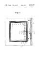
- FIG. 1is a top view of a preferred embodiment of the present invention
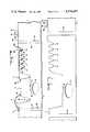
- FIG. 2is a view taken along the line 2--2 of FIG. 1;
- FIG. 3is a view as in FIG. 2 but prior to firing.
- FIGS. 1 and 2present a preferred embodiment of the invention.
- a substrate 1preferably of aluminum oxide.
- Element 2is a microelectronic device, commonly referred to as a die or chip which has been attached to substrate 1 in well 30 formed in the substrate with chip attachment material 7 which is known in the art.
- the chipis in electrical contact with conductive material 22 located in the via 8 which forms a power connection to the chip.
- the chipis located adjacent to through hole 9 which is a molded internal cooling passage of a desired geometry, not necessarily circular and passes entirely through the substrate.
- Through holes 15 and 16pass entirely through the substrate from top to bottom surfaces and have been filled with conductive material 23 to provide electrically conductive paths from one surface of the substrate to the other.
- Conductor 17has been silk screened onto the substrate and connects the conductive material of hole 16 to that of hole 15.
- Pad area 6has been molded into the top side of the substrate and has been filled with conductive material.
- the buss structure shownconsists of grooves 10, 11, 12, 13, and 14. These grooves have been dimensioned and contoured to accept a bonding tool that welds wire 3 to the conductive material 24 at the bottom of groove 14 at the weldment shown at location 14a.
- the other end of wire 3is shown welded to chip 2 at location 3a.
- Wire 4is shown welded to chip 2 at location 4a and to pad 6 at location 5.
- wire 3crosses the conductive material in the bottom of grooves 10, 11, 12 and 13 and is supported and maintained away from the conductive paths by the material separating the grooves.
- the buss structure groove material at its highest point of elevationis located a small distance ⁇ H below the topmost plane of the structure.
- Grooves 18, 19, 20 and 21have been filled with conductive material with a connection 25 shown running from hole 15 to conductor 18.
- FIG. 1the top surface of the substrate with chips connected thereon is shown.
- the chips 2are bonded to the substrate along the perimeter of a rectangle with connections 3 being made from chip pads to busses 10, 11, 12, 13 and/or 14.
- a lead 4is also connected from a pad on chip 2 to the conductive material 23 in hole 16.
- a bus 25is connected between conductive material 23 in hole 15 and bus 18.
- a channel 9 positioned in the substrate just below the chips 2is shown in phantom.
- a channel 9can be provided along the x and/or y axis and there can be several to remove heat from all chips on the substrate.
- FIG. 3shows the as molded green substrate that is shown in its fired and final assembled version in FIG. 1. Note the difference in the scale factors.
- the mold or die required to form the final configurationmust be scaled up from the dimensions of the final configuration by approximately 20 percent, i.e., the final desired dimensions must be multiplied by approximately 1.2 to determine the mold dimensions.
- the exact scaling factors involvedare highly dependent upon the specific formulations and processing techniques utilized.
- the shrinkage in processing and sinteringhowever is quite isotropic, so that all dimensions shrink very nearly to the same scale factor.
- the isotropic nature of the shrinkageinsure that the angles maintained are very nearly identical in the green and fired article.
- the molding material employed heretypically would be approximately 60% by volume of a fine grain aluminum oxide which has been milled to its ultimate crystal size and 40% by volume of a thermoplastic binder mixture.
- thermoplastic binder mixturewould be approximately one-third by weight of polyethylene, one-third by weight of paraffin wax, one-third by weight of beeswax with perhaps 0.1 though 0.2 percent of stearic acid added.
- the thermoplastic materials and aluminum oxideare mixed and blended together to a homogeneous mass at a temperature in excess of the melting point or flow point of the thermoplastic materials. Techniques for producing thermpolastic molding mixtures are well described in the prior art and will not be elaborated on here.
- the cooled green molding materialis crushed to pellet size or otherwise pelletized and is employed as a feed material for a substantially conventional plastic injection molding machine that has been suitably modified to accept abrasive materials.
- the moldis constructed of steel or aluminum by techniques and principles well known in the art of plastic injection molding.
- the substrateis then injection molded.
- the holes 9are formed, for example, by having an insert in the mold in the form of an electrically conductive wire of proper cross section and located where the holes are to be formed.
- the molded part with wireis removed from the mold and the wire is heated sufficiently to melt the binder immediately there around and permit axial removal of the wire, thereby leaving the hole 9 in the green substrate in the region where the wire had been.
- thermoplastic bindermust be removed from the substrate. This is conveniently accomplished by slowly heating the substrate at a low pressure to evaporate or sublime thermoplastic material out of the substrate body as described by Strivens, however other methods are equally appropriate.
- the substrateis then sintered with a sintering schedule and sintering atmosphere that is compatible for all the materials included in the substrate. If, for example, during substrate fabrication, a molybdenum metal face had been screened onto the green substrate at some portion of the manufacturing process, then the sintering atmosphere would best be reducing in nature. However, if the entire substrate is composed of an outside ceramic such as alumina, then the sintering is most conveniently performed in an air atmosphere. Beneficial use of sintering atmospheres is well known in the art.
- the next step in the manufacture of the subject circuitis to apply the metallization to the desired locations in and on the substrate.
- the techniques employed to do thisare well known in the art and the examples presented here are typical approaches that would be taken to achieve this objective.
- Grooves 18, 19, 20 and 21are most conveniently metallized by spreading an electrically conductive metal glass frit composite slurry such as is used for silk screen printing across the groove area, thereby filling the grooves.
- the metallizing pasteis dried and the substrate fired in accordance with the procedure required for the particular metallizing paste employed. As the groove structure under consideration here is located in the uppermost plane of the substrate, the metallizing paste that is bridging the gaps and spread about on the substrate surface in undesirable locations is most conveniently removed by mechanically abrading or lapping the uppermost surface.
- the conductor groovesare filled with a metallized material which has assumed the geometry of the grooves.
- Through holes 15 and 16are filled with the same pass of metallizing paste as was employed in the filling of grooves 18, 19, 20 and 21.
- bonding pad 6is also filled and bonding pad 6 is lapped back during the clean up operation that was employed to clean the regions surrounding the grooves 18, 19, 20 and 21.
- Conductor 17is applied in this example most typically by silk screening the metallizing paste so that a conductive path between the hole ends of holes 16 and 15 are joined by metallizing material.
- grooves 10, 11, 12, 13, 14 and groove 8are most conveniently filled with well known electrically conductive paste utilizing an inking pen of small bore capillary tubing.
- electrically conductive pasteutilizing an inking pen of small bore capillary tubing.
- the conductive pasteWhile the conductive paste is in its green form, it may be conveniently tested for continuity and interconductor short circuits and repaired at this time prior to firing.
- the substrateis fired at an elevated temperature with a time temperature atmosphere profile that has been established for optimum firing conditions for the paste being employed. It is obvious that a multiplicity of pastes and firing schedules may be employed for specific purposes, such as to apply resistant pads.
- the chip 2is attached to the substrate by any one of the chip attach techniques that are well known in the art.
- Element 7is shown and represents chip attach material that is unspecified in this description.
- Conductor 8has a low ohmic contact to chip 2 and represents in this description a power supply lead to chip 2.
- the active microelectronics located in and on chip 2are interconnected to the substrate through wires 3 and 4 at weldments 3a and 4a and weldments 5 and 14a.
- welding pad regions located at the surface of chip 2are provided for this express purpose.
- the metallizing materials employed at locations 5 and 14ahave been selected to be compatible with the weldment.
- wire 3in going from groove 14 to the pad located at 3a, crosses conductors 13, 12, 11 and 10.
- the dimensions of wire 3are normally on the order of 0.001 inches and the dimensions across the grooves 10, 11, 12, 13 and 14 would normally be on the order of 0.015 inches.
- the material conductor 3is composed of would normally or typically be aluminum with 1% silicon added.
- very large unit forceswould have to be applied to the wire 3 to cause it to contact the conductive material in one of the grooves across which the wire is suspended.
- the unit forceswould be the same as if it were a one inch diameter aluminum bar bridging a 15 inch gap.
- Cooling passage 9is utilized to withdraw thermal energy from the chip 2 to a remote location to maintain the chip temperature within desired limits. This may be done by circulating a fluid through cooling channel 9 of a lower temperature than chip 2 to create a temperature difference between chip 2 and the fluid in cooling channel 9, thereby causing a heat flow from chip 2 to the fluid in channel 9 in accordance with well known thermodynamic and heat transfer principles. Use may be made of local boiling such as is found in a heat pipe to achieve very high thermal flux densities in the region surrounding the chip. These techniques are well known in the art of heat transfer and thermal energy management and are obvious to anyone skilled in this art once the availability of cooling passage 9 is presented to them.
- While only a single hole 9is shown passing under a single row of chips in FIG. 1, it should be understood that the hole 9 or holes 9 can take other configurations.
- the hole 9 or holes 9can take other configurations.
- a single holecould be formed which is in the shape of a rectangle and passes under all chips 2 shown in FIG. 1 with closely adjacent entrance and exit for heat sink material disposed at a substrate edge. The latter embodiment would require molding of the substrate in two parts with half of the hole in each part. The parts would then be held together while in the green state in the shape of the final configuration with subsequent binder removal and sintering.
- the substrate materialwas sintered aluminum oxide.
- Other preferred embodimentsinclude the use of a metallic particulate material which has been mixed with a suitable plasticizing binder and molded into the desired complex geometry.
- the sintered metallic substratecould then be subsequently machined as in the case of the aluminum oxide substrate, but with the additional machine techniques that require a ductile or conductive material.
- precise configurationcould be coined into the surface as an extension of a crush forming operation or complex configurations could be electrically discharge machined into the surface.
- the substratewould then be coated with a thin layer of insulating material, such as glass.
- Another embodimentexists in the use of molding a highly loaded plastic system, such as a glass filled epoxy, and directly utilizing the as molded article for the interconnection structure without subsequent binder removal and sintering.
Landscapes
- Engineering & Computer Science (AREA)
- Microelectronics & Electronic Packaging (AREA)
- Computer Hardware Design (AREA)
- Power Engineering (AREA)
- Physics & Mathematics (AREA)
- Condensed Matter Physics & Semiconductors (AREA)
- General Physics & Mathematics (AREA)
- Manufacturing & Machinery (AREA)
- Chemical & Material Sciences (AREA)
- Materials Engineering (AREA)
- Cooling Or The Like Of Semiconductors Or Solid State Devices (AREA)
Abstract
Description
Claims (28)
Priority Applications (7)
| Application Number | Priority Date | Filing Date | Title |
|---|---|---|---|
| US06/174,929US4374457A (en) | 1980-08-04 | 1980-08-04 | Method of fabricating complex micro-circuit boards and substrates |
| US06/419,172US4531145A (en) | 1980-08-04 | 1982-09-17 | Method of fabricating complex micro-circuit boards and substrates and substrate |
| US06/584,309US4519447A (en) | 1980-08-04 | 1984-03-05 | Substrate cooling |
| US06/665,507US4562092A (en) | 1980-08-04 | 1984-10-30 | Method of fabricating complex microcircuit boards, substrates and microcircuits and the substrates and microcircuits |
| US07/214,796US4994215A (en) | 1980-08-04 | 1988-07-05 | Method of fabricating complex microcircuit boards, substrates and microcircuits and the substrates and microcircuits |
| US07/616,489US5234655A (en) | 1980-08-04 | 1990-11-21 | Method of forming a mold |
| US08/035,948US5271887A (en) | 1980-08-04 | 1993-03-23 | Method of fabricating complex micro-circuit boards, substrates and microcircuits and the substrates and microcircuits |
Applications Claiming Priority (1)
| Application Number | Priority Date | Filing Date | Title |
|---|---|---|---|
| US06/174,929US4374457A (en) | 1980-08-04 | 1980-08-04 | Method of fabricating complex micro-circuit boards and substrates |
Related Child Applications (3)
| Application Number | Title | Priority Date | Filing Date |
|---|---|---|---|
| US06/419,172DivisionUS4531145A (en) | 1980-08-04 | 1982-09-17 | Method of fabricating complex micro-circuit boards and substrates and substrate |
| US44501782AContinuation-In-Part | 1980-08-04 | 1982-11-29 | |
| US06468665Continuation-In-Part | 1983-02-22 |
Publications (1)
| Publication Number | Publication Date |
|---|---|
| US4374457Atrue US4374457A (en) | 1983-02-22 |
Family
ID=22638110
Family Applications (1)
| Application Number | Title | Priority Date | Filing Date |
|---|---|---|---|
| US06/174,929Expired - LifetimeUS4374457A (en) | 1980-08-04 | 1980-08-04 | Method of fabricating complex micro-circuit boards and substrates |
Country Status (1)
| Country | Link |
|---|---|
| US (1) | US4374457A (en) |
Cited By (62)
| Publication number | Priority date | Publication date | Assignee | Title |
|---|---|---|---|---|
| US4516148A (en)* | 1982-08-30 | 1985-05-07 | The Board Of Trustees Of The Leland Stanford, Jr. University | Semiconductor device having improved lead attachment |
| US4521449A (en)* | 1984-05-21 | 1985-06-04 | International Business Machines Corporation | Process for forming a high density metallurgy system on a substrate and structure thereof |
| US4524038A (en)* | 1981-12-19 | 1985-06-18 | Robert Bosch Gmbh | Method of making a vibration-resistant electrical component and connection lead combination, particularly exhaust gas composition sensor |
| US4532152A (en)* | 1982-03-05 | 1985-07-30 | Elarde Vito D | Fabrication of a printed circuit board with metal-filled channels |
| US4546065A (en)* | 1983-08-08 | 1985-10-08 | International Business Machines Corporation | Process for forming a pattern of metallurgy on the top of a ceramic substrate |
| US4552615A (en)* | 1984-05-21 | 1985-11-12 | International Business Machines Corporation | Process for forming a high density metallurgy system on a substrate and structure thereof |
| US4562092A (en)* | 1980-08-04 | 1985-12-31 | Fine Particle Technology Corporation | Method of fabricating complex microcircuit boards, substrates and microcircuits and the substrates and microcircuits |
| US4570337A (en)* | 1982-04-19 | 1986-02-18 | Olin Corporation | Method of assembling a chip carrier |
| US4604678A (en)* | 1983-07-18 | 1986-08-05 | Frederick Parker | Circuit board with high density electrical tracers |
| DE3507341A1 (en)* | 1982-12-06 | 1986-09-04 | Fine Particle Technology Corp., Camarillo, Calif. | Method for forming electrically conductive tracks on a substrate |
| US4645733A (en)* | 1983-11-10 | 1987-02-24 | Sullivan Donald F | High resolution printed circuits formed in photopolymer pattern indentations overlaying printed wiring board substrates |
| US4649497A (en)* | 1983-06-03 | 1987-03-10 | John Fluke Mfg. Co., Inc. | Computer-produced circuit board |
| WO1988002542A1 (en)* | 1986-09-26 | 1988-04-07 | Hypres, Incorporated | Low-temperature monolithic chip |
| WO1988004829A1 (en)* | 1986-12-17 | 1988-06-30 | Raychem Corporation | Interconnection of electronic components |
| US4756929A (en)* | 1983-11-10 | 1988-07-12 | Sullivan Donald F | High density printing wiring |
| US4893216A (en)* | 1988-08-09 | 1990-01-09 | Northern Telecom Limited | Circuit board and method of soldering |
| US4912844A (en)* | 1988-08-10 | 1990-04-03 | Dimensional Circuits Corporation | Methods of producing printed circuit boards |
| US4955523A (en)* | 1986-12-17 | 1990-09-11 | Raychem Corporation | Interconnection of electronic components |
| US4985601A (en)* | 1989-05-02 | 1991-01-15 | Hagner George R | Circuit boards with recessed traces |
| US4985600A (en)* | 1988-09-30 | 1991-01-15 | Siemens Aktiengesellschaft | Printed circuit board having an injection molded substrate |
| US4994215A (en)* | 1980-08-04 | 1991-02-19 | Fine Particle Technology Corp. | Method of fabricating complex microcircuit boards, substrates and microcircuits and the substrates and microcircuits |
| US4996391A (en)* | 1988-09-30 | 1991-02-26 | Siemens Aktiengesellschaft | Printed circuit board having an injection molded substrate |
| US5014419A (en)* | 1987-05-21 | 1991-05-14 | Cray Computer Corporation | Twisted wire jumper electrical interconnector and method of making |
| US5045975A (en)* | 1987-05-21 | 1991-09-03 | Cray Computer Corporation | Three dimensionally interconnected module assembly |
| US5054192A (en)* | 1987-05-21 | 1991-10-08 | Cray Computer Corporation | Lead bonding of chips to circuit boards and circuit boards to circuit boards |
| US5055637A (en)* | 1989-05-02 | 1991-10-08 | Hagner George R | Circuit boards with recessed traces |
| US5086334A (en)* | 1989-12-08 | 1992-02-04 | Cray Research Inc. | Chip carrier |
| US5112232A (en)* | 1987-05-21 | 1992-05-12 | Cray Computer Corporation | Twisted wire jumper electrical interconnector |
| US5122326A (en)* | 1987-03-02 | 1992-06-16 | Vacuum Industries Inc. | Method of removing binder material from shaped articles under vacuum pressure conditions |
| US5127986A (en)* | 1989-12-01 | 1992-07-07 | Cray Research, Inc. | High power, high density interconnect method and apparatus for integrated circuits |
| US5134247A (en)* | 1989-02-21 | 1992-07-28 | Cray Research Inc. | Reduced capacitance chip carrier |
| US5166097A (en)* | 1990-11-26 | 1992-11-24 | The Boeing Company | Silicon wafers containing conductive feedthroughs |
| US5184400A (en)* | 1987-05-21 | 1993-02-09 | Cray Computer Corporation | Method for manufacturing a twisted wire jumper electrical interconnector |
| US5185502A (en)* | 1989-12-01 | 1993-02-09 | Cray Research, Inc. | High power, high density interconnect apparatus for integrated circuits |
| US5189507A (en)* | 1986-12-17 | 1993-02-23 | Raychem Corporation | Interconnection of electronic components |
| US5196990A (en)* | 1990-03-01 | 1993-03-23 | Fuji Electric Co., Ltd. | Metal printed circuit board |
| US5196377A (en)* | 1990-12-20 | 1993-03-23 | Cray Research, Inc. | Method of fabricating silicon-based carriers |
| US5195237A (en)* | 1987-05-21 | 1993-03-23 | Cray Computer Corporation | Flying leads for integrated circuits |
| US5208450A (en)* | 1988-04-20 | 1993-05-04 | Matsushita Electric Industrial Co., Ltd. | IC card and a method for the manufacture of the same |
| US5257178A (en)* | 1991-12-19 | 1993-10-26 | General Electric Company | Method of optimally operating a computer numerical control milling machine to mill optimal high density interconnect substrates |
| US5358826A (en)* | 1989-04-25 | 1994-10-25 | Cray Research, Inc. | Method of fabricating metallized chip carries from wafer-shaped substrates |
| US5380476A (en)* | 1989-01-20 | 1995-01-10 | Kawasaki Steel Corporation | Method of debinding for injection molded objects |
| US5718789A (en)* | 1995-06-07 | 1998-02-17 | The Dexter Corporation | Method for making a debossed conductive film composite |
| US5729050A (en)* | 1996-03-11 | 1998-03-17 | Lg Semicon Co., Ltd. | Semiconductor package substrate and ball grid array (BGA) semiconductor package using same |
| US5731086A (en)* | 1995-06-07 | 1998-03-24 | Gebhardt; William F. | Debossable films |
| US5737387A (en)* | 1994-03-11 | 1998-04-07 | Arch Development Corporation | Cooling for a rotating anode X-ray tube |
| US5761801A (en)* | 1995-06-07 | 1998-06-09 | The Dexter Corporation | Method for making a conductive film composite |
| US5820014A (en) | 1993-11-16 | 1998-10-13 | Form Factor, Inc. | Solder preforms |
| US5925203A (en)* | 1996-01-30 | 1999-07-20 | Sarnoff Corporation | Method of making a plasma display |
| US5928767A (en)* | 1995-06-07 | 1999-07-27 | Dexter Corporation | Conductive film composite |
| US5994152A (en) | 1996-02-21 | 1999-11-30 | Formfactor, Inc. | Fabricating interconnects and tips using sacrificial substrates |
| US6160714A (en)* | 1997-12-31 | 2000-12-12 | Elpac (Usa), Inc. | Molded electronic package and method of preparation |
| US6212072B1 (en) | 1999-05-19 | 2001-04-03 | Sagem Sa | Electronics package on a plate, and a method of making such a package |
| US6219253B1 (en) | 1997-12-31 | 2001-04-17 | Elpac (Usa), Inc. | Molded electronic package, method of preparation using build up technology and method of shielding |
| US6274823B1 (en) | 1993-11-16 | 2001-08-14 | Formfactor, Inc. | Interconnection substrates with resilient contact structures on both sides |
| US20020053734A1 (en)* | 1993-11-16 | 2002-05-09 | Formfactor, Inc. | Probe card assembly and kit, and methods of making same |
| US20030015789A1 (en)* | 2001-01-30 | 2003-01-23 | Jon Zuo | Semiconductor package with lid heat spreader |
| US20060237856A1 (en)* | 1993-11-16 | 2006-10-26 | Formfactor, Inc. | Microelectronic Contact Structure And Method Of Making Same |
| US20090126857A1 (en)* | 2007-11-15 | 2009-05-21 | Shin Hyun-Ok | Manufacturing method of low temperature co-fired ceramics substrate |
| US20100093229A1 (en)* | 1996-02-21 | 2010-04-15 | Formfactor, Inc. | Microelectronic contact structure and method of making same |
| EP2765840A3 (en)* | 2013-02-08 | 2014-11-12 | SEMIKRON Elektronik GmbH & Co. KG | Switching assembly |
| US12207400B2 (en)* | 2021-11-04 | 2025-01-21 | Shinko Electric Industries Co., Ltd. | Metal component and ceramic substrate |
Citations (2)
| Publication number | Priority date | Publication date | Assignee | Title |
|---|---|---|---|---|
| US3438127A (en)* | 1965-10-21 | 1969-04-15 | Friden Inc | Manufacture of circuit modules using etched molds |
| US4289719A (en)* | 1976-12-10 | 1981-09-15 | International Business Machines Corporation | Method of making a multi-layer ceramic substrate |
- 1980
- 1980-08-04USUS06/174,929patent/US4374457A/ennot_activeExpired - Lifetime
Patent Citations (2)
| Publication number | Priority date | Publication date | Assignee | Title |
|---|---|---|---|---|
| US3438127A (en)* | 1965-10-21 | 1969-04-15 | Friden Inc | Manufacture of circuit modules using etched molds |
| US4289719A (en)* | 1976-12-10 | 1981-09-15 | International Business Machines Corporation | Method of making a multi-layer ceramic substrate |
Cited By (73)
| Publication number | Priority date | Publication date | Assignee | Title |
|---|---|---|---|---|
| US4562092A (en)* | 1980-08-04 | 1985-12-31 | Fine Particle Technology Corporation | Method of fabricating complex microcircuit boards, substrates and microcircuits and the substrates and microcircuits |
| US4994215A (en)* | 1980-08-04 | 1991-02-19 | Fine Particle Technology Corp. | Method of fabricating complex microcircuit boards, substrates and microcircuits and the substrates and microcircuits |
| US4524038A (en)* | 1981-12-19 | 1985-06-18 | Robert Bosch Gmbh | Method of making a vibration-resistant electrical component and connection lead combination, particularly exhaust gas composition sensor |
| US4532152A (en)* | 1982-03-05 | 1985-07-30 | Elarde Vito D | Fabrication of a printed circuit board with metal-filled channels |
| US4570337A (en)* | 1982-04-19 | 1986-02-18 | Olin Corporation | Method of assembling a chip carrier |
| US4516148A (en)* | 1982-08-30 | 1985-05-07 | The Board Of Trustees Of The Leland Stanford, Jr. University | Semiconductor device having improved lead attachment |
| DE3507341A1 (en)* | 1982-12-06 | 1986-09-04 | Fine Particle Technology Corp., Camarillo, Calif. | Method for forming electrically conductive tracks on a substrate |
| US4649497A (en)* | 1983-06-03 | 1987-03-10 | John Fluke Mfg. Co., Inc. | Computer-produced circuit board |
| US4604678A (en)* | 1983-07-18 | 1986-08-05 | Frederick Parker | Circuit board with high density electrical tracers |
| US4546065A (en)* | 1983-08-08 | 1985-10-08 | International Business Machines Corporation | Process for forming a pattern of metallurgy on the top of a ceramic substrate |
| EP0133917A3 (en)* | 1983-08-08 | 1987-03-25 | International Business Machines Corporation | Process for forming a pattern of electrically conductive lines on the top of a ceramic substrate |
| US4756929A (en)* | 1983-11-10 | 1988-07-12 | Sullivan Donald F | High density printing wiring |
| US4645733A (en)* | 1983-11-10 | 1987-02-24 | Sullivan Donald F | High resolution printed circuits formed in photopolymer pattern indentations overlaying printed wiring board substrates |
| US4521449A (en)* | 1984-05-21 | 1985-06-04 | International Business Machines Corporation | Process for forming a high density metallurgy system on a substrate and structure thereof |
| US4552615A (en)* | 1984-05-21 | 1985-11-12 | International Business Machines Corporation | Process for forming a high density metallurgy system on a substrate and structure thereof |
| US4809133A (en)* | 1986-09-26 | 1989-02-28 | Hypres, Inc. | Low temperature monolithic chip |
| WO1988002542A1 (en)* | 1986-09-26 | 1988-04-07 | Hypres, Incorporated | Low-temperature monolithic chip |
| US4955523A (en)* | 1986-12-17 | 1990-09-11 | Raychem Corporation | Interconnection of electronic components |
| WO1988004829A1 (en)* | 1986-12-17 | 1988-06-30 | Raychem Corporation | Interconnection of electronic components |
| US5189507A (en)* | 1986-12-17 | 1993-02-23 | Raychem Corporation | Interconnection of electronic components |
| US5122326A (en)* | 1987-03-02 | 1992-06-16 | Vacuum Industries Inc. | Method of removing binder material from shaped articles under vacuum pressure conditions |
| US5195237A (en)* | 1987-05-21 | 1993-03-23 | Cray Computer Corporation | Flying leads for integrated circuits |
| US5112232A (en)* | 1987-05-21 | 1992-05-12 | Cray Computer Corporation | Twisted wire jumper electrical interconnector |
| US5184400A (en)* | 1987-05-21 | 1993-02-09 | Cray Computer Corporation | Method for manufacturing a twisted wire jumper electrical interconnector |
| US5014419A (en)* | 1987-05-21 | 1991-05-14 | Cray Computer Corporation | Twisted wire jumper electrical interconnector and method of making |
| US5045975A (en)* | 1987-05-21 | 1991-09-03 | Cray Computer Corporation | Three dimensionally interconnected module assembly |
| US5054192A (en)* | 1987-05-21 | 1991-10-08 | Cray Computer Corporation | Lead bonding of chips to circuit boards and circuit boards to circuit boards |
| US5208450A (en)* | 1988-04-20 | 1993-05-04 | Matsushita Electric Industrial Co., Ltd. | IC card and a method for the manufacture of the same |
| US4893216A (en)* | 1988-08-09 | 1990-01-09 | Northern Telecom Limited | Circuit board and method of soldering |
| US4912844A (en)* | 1988-08-10 | 1990-04-03 | Dimensional Circuits Corporation | Methods of producing printed circuit boards |
| US4996391A (en)* | 1988-09-30 | 1991-02-26 | Siemens Aktiengesellschaft | Printed circuit board having an injection molded substrate |
| US4985600A (en)* | 1988-09-30 | 1991-01-15 | Siemens Aktiengesellschaft | Printed circuit board having an injection molded substrate |
| US5380476A (en)* | 1989-01-20 | 1995-01-10 | Kawasaki Steel Corporation | Method of debinding for injection molded objects |
| US5134247A (en)* | 1989-02-21 | 1992-07-28 | Cray Research Inc. | Reduced capacitance chip carrier |
| US5358826A (en)* | 1989-04-25 | 1994-10-25 | Cray Research, Inc. | Method of fabricating metallized chip carries from wafer-shaped substrates |
| US5055637A (en)* | 1989-05-02 | 1991-10-08 | Hagner George R | Circuit boards with recessed traces |
| US4985601A (en)* | 1989-05-02 | 1991-01-15 | Hagner George R | Circuit boards with recessed traces |
| US5185502A (en)* | 1989-12-01 | 1993-02-09 | Cray Research, Inc. | High power, high density interconnect apparatus for integrated circuits |
| US5127986A (en)* | 1989-12-01 | 1992-07-07 | Cray Research, Inc. | High power, high density interconnect method and apparatus for integrated circuits |
| US5086334A (en)* | 1989-12-08 | 1992-02-04 | Cray Research Inc. | Chip carrier |
| US5196990A (en)* | 1990-03-01 | 1993-03-23 | Fuji Electric Co., Ltd. | Metal printed circuit board |
| US5510655A (en)* | 1990-11-26 | 1996-04-23 | The Boeing Company | Silicon wafers containing conductive feedthroughs |
| US5166097A (en)* | 1990-11-26 | 1992-11-24 | The Boeing Company | Silicon wafers containing conductive feedthroughs |
| US5196377A (en)* | 1990-12-20 | 1993-03-23 | Cray Research, Inc. | Method of fabricating silicon-based carriers |
| US5257178A (en)* | 1991-12-19 | 1993-10-26 | General Electric Company | Method of optimally operating a computer numerical control milling machine to mill optimal high density interconnect substrates |
| US7601039B2 (en) | 1993-11-16 | 2009-10-13 | Formfactor, Inc. | Microelectronic contact structure and method of making same |
| US20020053734A1 (en)* | 1993-11-16 | 2002-05-09 | Formfactor, Inc. | Probe card assembly and kit, and methods of making same |
| US6274823B1 (en) | 1993-11-16 | 2001-08-14 | Formfactor, Inc. | Interconnection substrates with resilient contact structures on both sides |
| US20060237856A1 (en)* | 1993-11-16 | 2006-10-26 | Formfactor, Inc. | Microelectronic Contact Structure And Method Of Making Same |
| US8373428B2 (en) | 1993-11-16 | 2013-02-12 | Formfactor, Inc. | Probe card assembly and kit, and methods of making same |
| US5820014A (en) | 1993-11-16 | 1998-10-13 | Form Factor, Inc. | Solder preforms |
| US5737387A (en)* | 1994-03-11 | 1998-04-07 | Arch Development Corporation | Cooling for a rotating anode X-ray tube |
| US5928767A (en)* | 1995-06-07 | 1999-07-27 | Dexter Corporation | Conductive film composite |
| US5761801A (en)* | 1995-06-07 | 1998-06-09 | The Dexter Corporation | Method for making a conductive film composite |
| US5731086A (en)* | 1995-06-07 | 1998-03-24 | Gebhardt; William F. | Debossable films |
| US5718789A (en)* | 1995-06-07 | 1998-02-17 | The Dexter Corporation | Method for making a debossed conductive film composite |
| US5925203A (en)* | 1996-01-30 | 1999-07-20 | Sarnoff Corporation | Method of making a plasma display |
| US5994152A (en) | 1996-02-21 | 1999-11-30 | Formfactor, Inc. | Fabricating interconnects and tips using sacrificial substrates |
| US8033838B2 (en) | 1996-02-21 | 2011-10-11 | Formfactor, Inc. | Microelectronic contact structure |
| US20100093229A1 (en)* | 1996-02-21 | 2010-04-15 | Formfactor, Inc. | Microelectronic contact structure and method of making same |
| US5729050A (en)* | 1996-03-11 | 1998-03-17 | Lg Semicon Co., Ltd. | Semiconductor package substrate and ball grid array (BGA) semiconductor package using same |
| US6160714A (en)* | 1997-12-31 | 2000-12-12 | Elpac (Usa), Inc. | Molded electronic package and method of preparation |
| US6519161B1 (en) | 1997-12-31 | 2003-02-11 | William J. Green | Molded electronic package, method of preparation and method of shielding-II |
| US6219253B1 (en) | 1997-12-31 | 2001-04-17 | Elpac (Usa), Inc. | Molded electronic package, method of preparation using build up technology and method of shielding |
| US6212072B1 (en) | 1999-05-19 | 2001-04-03 | Sagem Sa | Electronics package on a plate, and a method of making such a package |
| US6858929B2 (en) | 2001-01-30 | 2005-02-22 | Thermal Corp. | Semiconductor package with lid heat spreader |
| US20050093139A1 (en)* | 2001-01-30 | 2005-05-05 | Jon Zuo | Semiconductor package with lid heat spreader |
| US7005738B2 (en) | 2001-01-30 | 2006-02-28 | Thermal Corp. | Semiconductor package with lid heat spreader |
| US6525420B2 (en) | 2001-01-30 | 2003-02-25 | Thermal Corp. | Semiconductor package with lid heat spreader |
| US20030015789A1 (en)* | 2001-01-30 | 2003-01-23 | Jon Zuo | Semiconductor package with lid heat spreader |
| US20090126857A1 (en)* | 2007-11-15 | 2009-05-21 | Shin Hyun-Ok | Manufacturing method of low temperature co-fired ceramics substrate |
| EP2765840A3 (en)* | 2013-02-08 | 2014-11-12 | SEMIKRON Elektronik GmbH & Co. KG | Switching assembly |
| US12207400B2 (en)* | 2021-11-04 | 2025-01-21 | Shinko Electric Industries Co., Ltd. | Metal component and ceramic substrate |
Similar Documents
| Publication | Publication Date | Title |
|---|---|---|
| US4374457A (en) | Method of fabricating complex micro-circuit boards and substrates | |
| US4994215A (en) | Method of fabricating complex microcircuit boards, substrates and microcircuits and the substrates and microcircuits | |
| US4531145A (en) | Method of fabricating complex micro-circuit boards and substrates and substrate | |
| US4562092A (en) | Method of fabricating complex microcircuit boards, substrates and microcircuits and the substrates and microcircuits | |
| US6132543A (en) | Method of manufacturing a packaging substrate | |
| US12300578B2 (en) | Aluminum nitride multilayer power module interposer and method | |
| US4681656A (en) | IC carrier system | |
| US5508559A (en) | Power circuit package | |
| US5798469A (en) | Non-sintering controlled pattern formation | |
| EP3588553B1 (en) | Microelectronic modules including thermal extension levels and methods for the fabrication thereof | |
| US5271887A (en) | Method of fabricating complex micro-circuit boards, substrates and microcircuits and the substrates and microcircuits | |
| KR20020084684A (en) | Electrically isolated power device package | |
| GB2117686A (en) | Cast solder leads for leadless semiconductor circuits | |
| US11804421B2 (en) | Connecting clip design for pressure sintering | |
| US10806021B2 (en) | Packaged microelectronic component mounting using sinter attachment | |
| US20020003137A1 (en) | Contact heating device | |
| US5302219A (en) | Method for obtaining via patterns in ceramic sheets | |
| US20080197172A1 (en) | Bonding Tool | |
| EP3962244A1 (en) | Substrate with thermal vias and sinter-bonded thermal dissipation structure | |
| US5234655A (en) | Method of forming a mold | |
| CN102160170A (en) | Laminated quadrilateral prefabricated component package, system using the component package, and manufacturing method thereof | |
| US20080296753A1 (en) | Molded ceramic surface mount package | |
| CN108417500B (en) | Semiconductor device and method of manufacturing the same | |
| GB2136210A (en) | Method of Forming Substrates | |
| US6399182B1 (en) | Die attachment utilizing grooved surfaces |
Legal Events
| Date | Code | Title | Description |
|---|---|---|---|
| AS | Assignment | Owner name:CANTOR JAY M 9 OVERPOND CURT POTOMAC MD.20854 Free format text:ASSIGNOR ASSIGNS 10% OF HIS ENTIRE INTEREST TO SAID ASSIGNEE;ASSIGNOR:WIECH, RAYMOND E. JR.;REEL/FRAME:003953/0931 Effective date:19820302 Owner name:CANTOR JAY, MARYLAND Free format text:ASSIGNOR ASSIGNS 10% OF HIS ENTIRE INTEREST TO SAID ASSIGNEE;ASSIGNOR:WIECH, RAYMOND E. JR.;REEL/FRAME:003953/0931 Effective date:19820302 | |
| STCF | Information on status: patent grant | Free format text:PATENTED CASE | |
| AS | Assignment | Owner name:ENOMOTO INTERNATIONAL, A CORP. OF CA.,CALIFORNIA Free format text:ASSIGNMENT OF ASSIGNORS INTEREST;ASSIGNORS:WIECH, RAYMOND E. JR.;MAYA ELECTRONICS CORPORATION;WITEC CAYMAN PATENTS, LTD.;REEL/FRAME:004656/0255 Effective date:19870121 Owner name:ENOMOTO INTERNATIONAL, 3710 TRIPP ROAD, WOODSIDE, Free format text:ASSIGNMENT OF ASSIGNORS INTEREST.;ASSIGNORS:WIECH, RAYMOND E. JR.;MAYA ELECTRONICS CORPORATION;WITEC CAYMAN PATENTS, LTD.;REEL/FRAME:004656/0255 Effective date:19870121 | |
| AS | Assignment | Owner name:FINE PARTICLE TECHNOLOGY CORP. Free format text:ASSIGNMENT OF ASSIGNORS INTEREST.;ASSIGNORS:WIECH, RAYMOND E., JR.;CANTOR, JAY M.;MAYA ELECTRONICS CORPORATION;REEL/FRAME:005264/0267 Effective date:19850507 | |
| AS | Assignment | Owner name:FINE PARTICLE TECHNOLOGY CORP. Free format text:ASSIGN ENTIRE INTEREST SUBJECT TO RECITATION.;ASSIGNOR:WIECH, GENEVA, EXECUTRIX OF THE ESTATE OF WIECH, RAYMOND E. JR.;REEL/FRAME:005289/0567 Effective date:19900416 | |
| AS | Assignment | Owner name:FINE PARTICLE TECHNOLOGY CORP. Free format text:ASSIGNMENT OF ASSIGNORS INTEREST;ASSIGNOR:WIECH, GENEVA, SOLE BENEFICIARY OF THE ESTATE OF WIECH, RAYMOND E., JR., DEC'D;REEL/FRAME:005368/0258 Effective date:19900518 | |
| AS | Assignment | Owner name:FINE PARTICLE TECHNOLOGY CORPORATION, CALIFORNIA Free format text:ASIGNS THE ENTIRE INTEREST AND RIGHTS, IN ACCORDANCE TO THE DECLARATION SUBMITTED;;ASSIGNOR:BROWN, CHARLES;REEL/FRAME:005856/0823 Effective date:19900904 | |
| AS | Assignment | Owner name:WITEC CAYMAN PATENTS, LTD., CALIFORNIA Free format text:ASSIGNMENT OF ASSIGNORS INTEREST.;ASSIGNOR:FINE PARTICLE TECHNOLOGY CORPORATION;REEL/FRAME:005863/0838 Effective date:19910930 |