US4374437A - Variable ramp speed TV tuning system for rapid channel tuning - Google Patents
Variable ramp speed TV tuning system for rapid channel tuningDownload PDFInfo
- Publication number
- US4374437A US4374437AUS06/220,619US22061980AUS4374437AUS 4374437 AUS4374437 AUS 4374437AUS 22061980 AUS22061980 AUS 22061980AUS 4374437 AUS4374437 AUS 4374437A
- Authority
- US
- United States
- Prior art keywords
- tuning
- frequency
- signal
- counter
- channel
- Prior art date
- Legal status (The legal status is an assumption and is not a legal conclusion. Google has not performed a legal analysis and makes no representation as to the accuracy of the status listed.)
- Expired - Fee Related
Links
- 230000003247decreasing effectEffects0.000claimsdescription10
- 238000012937correctionMethods0.000claimsdescription6
- 230000004044responseEffects0.000claimsdescription5
- 238000000034methodMethods0.000abstractdescription6
- 230000015572biosynthetic processEffects0.000abstractdescription5
- 238000003786synthesis reactionMethods0.000abstractdescription5
- 230000008569processEffects0.000abstractdescription3
- 239000003990capacitorSubstances0.000description8
- 238000010586diagramMethods0.000description8
- 230000008859changeEffects0.000description7
- 238000013459approachMethods0.000description6
- 238000013461designMethods0.000description5
- 238000005259measurementMethods0.000description4
- 230000002194synthesizing effectEffects0.000description4
- 230000007704transitionEffects0.000description4
- 230000001934delayEffects0.000description3
- 230000006870functionEffects0.000description3
- 239000013078crystalSubstances0.000description2
- 238000012986modificationMethods0.000description2
- 230000004048modificationEffects0.000description2
- 230000009467reductionEffects0.000description2
- 238000012360testing methodMethods0.000description2
- 230000002457bidirectional effectEffects0.000description1
- 230000015556catabolic processEffects0.000description1
- 238000001514detection methodMethods0.000description1
- 230000005669field effectEffects0.000description1
- 238000001914filtrationMethods0.000description1
- 230000000977initiatory effectEffects0.000description1
- 238000004519manufacturing processMethods0.000description1
- 230000003534oscillatory effectEffects0.000description1
- 238000012545processingMethods0.000description1
- 238000009877renderingMethods0.000description1
- 238000001228spectrumMethods0.000description1
Images


Classifications
- H—ELECTRICITY
- H03—ELECTRONIC CIRCUITRY
- H03J—TUNING RESONANT CIRCUITS; SELECTING RESONANT CIRCUITS
- H03J1/00—Details of adjusting, driving, indicating, or mechanical control arrangements for resonant circuits in general
- H03J1/0008—Details of adjusting, driving, indicating, or mechanical control arrangements for resonant circuits in general using a central processing unit, e.g. a microprocessor
- H03J1/0041—Details of adjusting, driving, indicating, or mechanical control arrangements for resonant circuits in general using a central processing unit, e.g. a microprocessor for frequency synthesis with counters or frequency dividers
- H—ELECTRICITY
- H03—ELECTRONIC CIRCUITRY
- H03J—TUNING RESONANT CIRCUITS; SELECTING RESONANT CIRCUITS
- H03J7/00—Automatic frequency control; Automatic scanning over a band of frequencies
- H03J7/18—Automatic scanning over a band of frequencies
- H03J7/20—Automatic scanning over a band of frequencies where the scanning is accomplished by varying the electrical characteristics of a non-mechanically adjustable element
- H03J7/24—Automatic scanning over a band of frequencies where the scanning is accomplished by varying the electrical characteristics of a non-mechanically adjustable element using varactors, i.e. voltage variable reactive diodes
- H03J7/26—Automatic scanning over a band of frequencies where the scanning is accomplished by varying the electrical characteristics of a non-mechanically adjustable element using varactors, i.e. voltage variable reactive diodes in which an automatic frequency control circuit is brought into action after the scanning action has been stopped
Definitions
- This inventionrelates in general to television tuning systems and in particular to a microcomputer-controlled automatic frequency synthesis television tuning system for rapidly tuning to a selected channel.
- Frequency synthesizing tuning systemsoffer many advantages including enhanced tuning accuracy and, as a result, are being employed on an ever increasing basis in current production tuning systems.
- One frequency synthesizer currently in common useis termed the indirect frequency synthesizing tuning system in that it uses a programmable phase-locked loop for controlling and maintaining a desired output frequency.
- This tuning approachoffers the advantages of relatively low cost, improved frequency stability, and wide bandwidth coverage.
- the primary limitation of frequency synthesizers incorporating a phase-locked looprelates to their relatively slow inter-channel tuning rate. This operating limitation of frequency synthesizing tuners having a phase-locked loop severely limits their utility in applications involving a very rapid change from one output frequency to another desired output frequency.
- One outputrepresents identical frequency inputs provided to it, a second output provides a signal when the digit representation at its one input represents a value larger than that of the digit representation at its other input, and a third output provides a signal when the digit representation at its one input represents a value smaller than that of the digit representation and its other input.
- the number of reversals of the inequality represented by the output of this comparatordetermines the respective level of the rate of change of the tuning voltage. The smaller the number of changes in inequality results, i.e., the smaller the difference between the two numbers, the lower the tuning rate.
- channel acquisition timeis reduced by initially overriding the phase comparator in a phase-lock loop and ramping the tuning system toward the desired frequency until that frequency is passed at which time normal phase-lock loop tuning occurs.
- the systemgoes into full ramping, senses when the desired frequency has been passed, operates for a fixed time in a single frequency mode (with a PLL) and releases to a tuning window mode with AFC.
- the inventionis directed to a 100% ramping feature, i.e., driving the varactor-controlled oscillator to rapidly change frequency, until an overshoot condition is detected, which shortens the channel acquisition, or tuning, time. This approach places high demands on overshoot voltage detection which must not only be accurately detected, but also sensed immediately after tuning voltage crossing.
- Still another object of the present inventionis to provide a television tuning system in which tuner ramping speed is changed during channel seek in a manner to permit extremely rapid channel acquisition.
- FIG. 1which is partially in block diagram form and partially in schematic diagram form, shows a variable ramp speed television tuning system for rapid channel tuning in accordance with a preferred embodiment of the present invention
- FIG. 2shows in general a block diagram of the microcomputer utilized in the preferred embodiment of the present invention
- FIG. 3shows a block diagram of the timer and counter control utilized in the microcomputer shown in FIG. 2;
- FIG. 4is a flow chart depicting the steps required in the operation of the variable ramp speed television tuning system for rapid channel tuning shown in FIG. 1;
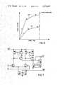
- FIG. 5shows the variable ramp speed utilized in the present invention for rapid channel tuning in the VHF and UHF bands
- FIG. 6is a circuit diagram of the ramp circuit for providing the tuning voltage to the tuner in acquiring the selected channel in accordance with the present invention
- FIG. 7is a schematic of the operational transconductance amplifiers of conventional design utilized in the ramping circuit shown in FIG. 6;
- FIG. 8is a schematic diagram of a programmable current source for providing the proper current in the lower operational transconductance amplifier of FIG. 6 to maintain the gain of the AFC feedback loop within the range required for its proper operation;
- FIG. 9is a schematic diagram of a programmable current source for providing the current to the upper operational transconductance amplifier of FIG. 6 required for the proper ramping speed in tuning to the selected channel.
- FIG. 1shows a variable ramp speed television tuning system for rapid channel tuning 20 in accordance with the present invention.
- Receiving antenna 22is coupled to a received, or radio, frequency amplifier 24 which, in turn, is coupled to a mixer 26.
- tuner local oscillator 28Also providing an input to mixer 26 is tuner local oscillator 28 with the output of mixer 26 being an intermediate frequency (IF) signal generated by combining the received signal with the tuner local oscillator signal.
- the IF signalis then amplified by the IF amplifier 30.
- Channel select means 32which may be either a key board entry device or a remote control transmitter operated by the viewer adjusts the frequency of the signal supplied to tuner oscillator 28. It is the signal provided by channel selector 32 to microcomputer 42 which represents the desired television channel.
- the received radio frequency carrier signalis converted to an IF amplitude modulating carrier which is amplified in amplifier 30 and provided to an automatic frequency control (AFC) system 34.
- AFCautomatic frequency control
- the output of tuner local oscillator 28is provided sequentially to prescaler 36 and divider 38 in generating a divided-down local oscillator signal which is provided to event counter 40 in microcomputer 42.
- Microcomputer 42measures the frequency of the tuner local oscillator signal, compares the tuner local oscillator signal frequency with a predetermined frequency representing the selected channel, determines whether tuner 28 is tuned too high or too low, and issues commands to ramp circuitry 44 to ramp the tuning voltage in the proper direction until the system reaches the desired frequency.
- This rampingis done using 3 speeds with the system ramping quickly at first and switching to slower speeds as it nears the desired frequency.
- the output of ramp circuit 44is transmitted by summer 48 back to tuner local oscillator 28 in tuning the television receiver to the selected channel.
- tuning system 20enters a received signal lock mode employing AFC system 34.
- AFC 34then maintains capacitory 46 at the proper voltage level in providing the proper signal level to tuner 28 during the phase lock mode of operation.
- Capacitor 47 in series with resistor 49permit rapid signal lock following tuner ramping.
- Microcomputer 42includes a reference crystal which drives a reference oscillator to generate a reference signal. This reference signal is provided to a reference divider which generates a divided-down reference signal to which the divided-down local oscillator signal is locked. Microcomputer 42 also includes a programmable divider which is controlled by data and instructions stored in microcomputer 42 for generating a divided-down local oscillator signal representing the selected channel number. This divided-down local oscillator signal is then compared with the divided-down reference oscillator signal typically in a phase comparator to generate a tuning signal which is then used to control the frequency of the local oscillator output in tuning to the selected channel.
- the front end of the variable ramp speed television tuning system 20including receiving antenna 22, RF amplifier 24, mixer 26, channel selector means 32, tuner local oscillator 28, and IF amplifier 30 may be of conventional design and do not form a part of the present invention and thus will not be described in greater detail.
- the local oscillator frequency signalis provided to prescaler 36 which is a fixed divide-by 256 prescaler.
- the output of prescaler 36is then provided to fixed divide-by 8 divider 38 to reduce the local oscillator signal to a frequency capable of being handled by microcomputer 42.
- the microcomputer utilized in the present inventionis the Single-Chip Microcomputer MK3870 made by various microcomputer manufacturers.
- the instruction register 50receives the operation code of the instruction to be executed from the program ROM 52 via data bus 54. Once latched into instruction register 50, the main control logic 56 decodes the instruction and provides the necessary control gating signals to all circuit elements.
- Four 11 bit registersare associated with the 2K ⁇ 8 ROM 52. These registers (not shown) are the Program Counter for addressing instructions or immediate operands, the Stack Register for saving the contents of the Program Counter during an interupt or subroutine call, the Data Counter for addressing data tables, and the Auxilliary Data counter.
- ROM Address Registers 58Associated with ROM Address Registers 58 is the 11 bit adder/incrementer used to increment the program counter or the data counter and to control various other ROM address register functions.
- the microcomputer program and data constantsare stored in Program ROM 52.
- Scratch Pad Registers 62provide 64 8-bit registers which may be used as general purpose RAM memory with Indirect Scratch Pad Address Register 64 as a 6-bit register being used to address the 64 scratch pad registers.
- the Arithmetic and Logic Unit (ALU) 66After receiving commands from Main Control Logic 56, the Arithmetic and Logic Unit (ALU) 66 performs required arithmetic or logic operations using the data presented on the two input buses and provides the result on the data bus.
- ALUArithmetic and Logic Unit
- Accumulator 68is a principal register for data manipulation within the 3870 Microcomputer and serves as one input to ALU 66 with the results of ALU operation being stored in Accumulator 68.
- Microcomputer timingis provided by 4 MHz crystal clock 70.
- Four complete bidirectional input/output ports 72are provided, with the capability to provide a test input to microcomputer Test Logic 74 also available.
- Power On Clear Control 76When power is applied to the MK3870 microcomputer 42 by means of Power On Clear Control 76 the program counter in ROM Address Register 58 and the interrupt control bit of the status register are cleared.
- Timer 78is an 8-bit binary down counter which is capable of operating in one of 3 modes: the Interval Timer Mode, the Pulse Width Measurement Mode, or the Event Counter Mode. As shown in FIG. 3, there is associated with timer 78 and 8-bit register called the Interrupt Control Port 80, a programmable prescaler 82, and an 8-bit modulo-N register 84.
- the desired timer mode, prescale value in programmable prescaler 82, the starting and stopping of timer 78, the active level of the EXT INT pin 86, and local enabling or disabling of interruptsare selected by outputting the proper bit configuration from accumulator 68 to interrupt control port 80 with the proper instruction.
- EXT INT 86is the external interrupt input which is used in conjunction with timer 78 for pulse width measurement and event counting.
- An interrupt control bitis used to allow or disallow interrupts in the 3870 Microcomputer. If the interrupt control bit is set and the 3870's interrupt with logic control 88 communicates an interrupt request to the CPU section, the interrupt will be acknowledged and processed upon completion of the first non-privileged instruction. If the Interrupt Control Bit is cleared, an interrupt request will not be acknowledged or processed until the Interrupt Control Bit is set.
- the present inventionmakes use of the 3870 Microcomputer in its Event Counter Mode which operates in the following manner.
- interrupt control port bit 4is cleared and all prescale bits (interrupt control port bits 5, 6, and 7) are cleared
- timer 78operates in the Event Counter Mode. This mode is used for counting pulses applied to the EXT INT pin 86. If interrupt control port bit 3 is set, timer 78 will decrement on each transition from the inactive level to the active level of EXT INT pin 86.
- Prescaler 82is not used in this mode, but as in the other two timer modes, timer 78 may be read at any time, may be stopped at any time by clearing interrupt port bit 3, and the timer interrupt request latch is set on the timer's transition from H "01" to H "N".
- Normally interrupt control port bit 0should be kept cleared in the event counter mode, otherwise, external interrupts will be generated on the transition from the inactive level to the active level of EXT INT pin 86.
- the minimum pulse width required on EXT INTis two internal clock periods and the minimum inactive time is two internal clock periods; therefore, the maximum repetition rate is 500 KHz.
- the prescaled and divided-down version of the local oscillator signalis provided to the External Time Base input of microcomputer 42.
- the local oscillator signalis then divided by 2 by a second divider 92 in microcomputer 42.
- the output of divider 92is then provided to prescaler 82 which is controlled by the inputs to interrupt control port 80.
- interrupt control port bit 4is cleared as are all the prescale bits, i.e., interrupt control port bits 5, 6, and 7.
- Interrupt control port bit 3is set in this mode and timer 78 decrements on each transition from the inactive level to the active level of the EXT INT pin 86.
- the output of prescaler 82is then provided to timer 78 which is an 8-bit down counter and which is preloaded with the contents of modulo-N register 84.
- the contents of modulo-N register 84 and the process of providing its contents to timer 78are well known in the art and will not be further discussed here.
- the contents of modulo-N register 84 and the information provided to timer 78are a function of the desired channel and are stored in and recalled from the microcomputer's ROM 52.
- the contents of modulo-N register 84determines the channel to be tuned to, the frequency band of the selected channel, and the rate at which tuning for that channel is accomplished as will be explained later.
- timer 78counts down to zero and sets timer interrupt request latch 94 once zero is reached.
- the microcomputer's clockis used as the time base for event counter 40.
- a resolution of one part in a thousand, or ten bits,is provided and in order to obtain this resolution event counter 90 is used over and over until the required resolution is obtained.
- timer interrupt request latch 94is set and countdown is re-initiated by timer 78.
- timer 78From the number of times timer 78 is decremented to zero as measured by timer interrupt request latch 94 and by the contents of timer 78 on termination of the counting interval, microcomputer 42 using primarily its ALU 66 and accumulator 68 determines whether the system is tuned too high or too low in frequency. Thus, when timer 78 is decremented to the value zero, it automatically resets itself to the preloaded value provided by modulo-N register 84, and provides an interrupt to timer interrupt request latch 94 and continues to decrement until zero is reached again. The time period during which timer 78 is enabled is determined by the frequency resolution required. The number of interrupts generated during this time period is determined by the channel frequency and the output of modulo-N register 84.
- the present inventionhas made use of conventional frequency synthesis tuner techniques as controlled by a microcomputer in generating a tuner voltage correction signal.
- Microcomputer MK3870is an off-the-shelf item and is being used in a conventional manner in the present application.
- the present inventioninvolves the specific counting technique utilized in generating a step-type tuning voltage correction signal as applied to ramping circuitry. The details of this unique tuning system are provided in the following paragraphs.
- the maximum ramping speed possibleis determined by the frequency resolution required in measuring the local oscillator signal frequency. Because in the present invention event counter 40 is enabled while the system is ramping, ramping speed may not be so fast that the count left over in event counter 40 changes more than one count during one counting interval. By the count left over is meant the residue remaining in event counter 40 at the end of the predetermined counting interval. If the frequency of the local oscillator signal has changed as a result of high speed ramping so much that during one counting interval the count residue has changed by two counts, the system would become unstable and be unable to determine whether to tune up or tune down in attempting to precisely tune to the desired frequency.
- the degree of frequency resolution requiredis determined by the interval over which the frequency is measured, or the counting interval, with higher frequency measuring resolution possible with increasing periods of frequency measurement.
- the desired frequencymay be rapidly approached and subsequently more accurately acquired by reducing the ramping speed while correspondingly increasing the frequency measuring interval.
- the present inventionthus makes use of three separate ramping speeds each possessing different frequency measurement resolutions and permits the television receiver to initially tune somewhat inaccurately at high speed to the channel while subsequently in a step-wise manner reducing the ramping speed, increasing frequency measuring resolution and more precisely tuning to the selected channel.
- the operation of the present inventionis best shown in the flow diagram of FIG.
- variable ramp speed channel tuning routineis entered from the main tuning program controlled by microcomputer 42.
- event counter 40is loaded with the modulo-M from modulo-N register 84. This modulo number represents the selected channel number and is provided to the modulo-N register 84 by microcomputer 42.
- the event counteris then started and the instructions are counted in a timing loop until a predetermined delay time T is reached.
- the event counteris then stopped and read. If during the counting time the counter reaches full count M, an interrupt is generated and the event counter 40 is reloaded and starts counting again.
- prescaler 36is turned on by a signal received from microcomputer 42.
- This prescaler "ON" signalis removed once the seek mode is completed and AFC 34 is initiated.
- This selective turning on and off of prescaler 36reduces the shielding requirements in tuner 20 since the prescaler 36 is not running during normal viewing.
- the interrupt counteris set up and event counter 40 is loaded with the appropriate modulo number.
- the channel selector 32e.g., a keyboard, is then scanned every 4 msec.
- the ramping speedis determined by the main tuning program before the flow chart shown in FIG. 4 is entered.
- the fast UHF loophas a frequency resolution of 6 MHz
- the medium speed loophas a frequency resolution of 1 MHz.
- loop frequency resolutionis the reciprocal of loop speed
- the fast loopis executed in one-sixth the slow loop time and in one-half the time of the medium speed loop.
- one-sixth the number of interruptsshould be encountered in the high speed loop as in the low speed ramping loop.
- a UHF channelis selected by the user, the counter is run for various time intervals depending upon which ramp speed loop the system is in. Timing intervals of 1880, 940, or 382 microseconds are introduced for the slow, medium and fast ramping rate loops, respectively. These decreasing timing intervals from low to high speed loops provide for the decreasing frequency resolution of the low, medium and high speed loops, respectively. If a VHF channel is selected by the user, the system proceeds to a dummy counter which introduces a 6 ⁇ multiple of the 1880, 940, or 382 microsecond timing interval for the VHF slow, medium, and fast ramping rates, respectively.
- the dummy counteris set at 6 and the routine decrements the counter from 6 to 1 and thus adds increasing time intervals to the VHF ramping rate loops.
- the VHF ramping loopsare of greater duration than the UHF loops because of the closer spacing of VHF channels and the need for greater frequency resolution in acquiring VHF channels.
- the variable ramping rate routinechecks once again to see if either a UHF or VHF channel has been selected and if a VHF channel has been selected, additional delays of 840, 420 or 138 microseconds are introduced into the routine for the slow, medium, and rapid tuning rate loops, respectively. These timing delays introduce the necessary timing increments for the required frequency resolution at the various loop speeds.
- the microcomputerincrements the interrupt counter and then returns to the flowchart shown in FIG. 4.
- the routinethen checks to determine the number of interrupts detected. If a UHF channel has been selected the routine proceeds directly to an interrupt check and the aforementioned timing delays are not introduced into the routine. The residual contents of the event counter are also checked. Each count in the event counter represents one frequency resolution step. If the number of interrupts detected is zero, less than three, or less than six, for the fast, medium, or slow ramp speed loops, respectively, the frequency of the tuner's local oscillator 28 is very low and a fast ramp-up mode is initiated by resetting the interrupt counter and reloading the event counter with the appropriate entry.
- the tuning loopis then re-initiated. If the number of interrupts detected is greater than 1, greater than 3 or greater than 6, for the fast, medium, or slow ramping rate loops, respectively, this indicates that the local oscillator frequency is very high and results in the initiation of a ramp-down mode by reloading the event counter and resetting the interrupt counter. If the system detects the correct number of interrupts for the particular speed loop just completed, the system compares the residual count with the correct count and initiates a ramp up if the residue is too large or a ramp down if the residue is too small. The ramp speeds are established by the main tuning program and are fixed prior to entering the flowchart of FIG. 4. The main tuning program proceeds through the fast, medium and slow ramping routines with the program shown in FIG.
- FIG. 4illustrates the variable tuning ramp speeds utilized for rapid channel tuning in the VHF and UHF bands as implemented in the present invention.
- microcomputer 42The manner in which a signal representing the local oscillator frequency is provided to microcomputer 42, the storing of a series of predetermined values representing selected channel numbers, the comparison of these predetermined values with the local oscillator signal frequency, and the generation of an output signal by microcomputer 42 representing the difference between these two frequency values as previously described and as embodied in the present invention involves techniques and components well-known in the art. Numerous applications involving the 3870 Microcomputer where various signal characteristics are sampled, compared with stored signal information, and used to generate signals representing the resulting difference signal are well-known in the signal processing arts. What distinguishes the present invention from the prior art is the unique way in which ramping speed and frequency measuring resolution are manipulated in a digital counting loop sequence in the signal scanning mode of a television receiver tuning system to permit the rapid and efficient tuning to a selected channel.
- microcomputer 42Based upon the comparison of the tuner local oscillator frequency and a pre-set, stored frequency value representing the selected channel, microcomputer 42 provides a high, medium, or low speed ramping signal to ramping circuit 44 as shown in FIG. 6.
- the ramping circuit shown in FIG. 6is conventional in design, thus only a general description of its operation and major components will be provided.
- the primary components or ramping circuit 44are upper and lower operational transconductance amplifiers (OTA) 96 and 98, respectively.
- OTAoperational transconductance amplifier
- OTA 96generates a ramping voltage by charging 10 microfarad capacitor 104 at its output.
- the tuning voltageis ramped up and down by the switching on and off of PNP transistors 106 and 108 connected to the inputs of OTA 96.
- transistor 106rendered conductive, tuner 28 is ramped up.
- transistor 106in a conducting state, tuner 28 is ramped downward.
- the inputs to the bases of transistors 106 and 108are provided by microcomputer 42.
- the ramping currentis either being provided to or removed from capacitor 104 in the form of biasing current to OTA 96 by ramp rate control circuit 100.
- the voltage on 10 microfarad capacitor 104is applied to the gate of field-effect transistor (FET) 111 which acts as a voltage follower to eliminate any voltage across resistor 112 during ramping only.
- FETfield-effect transistor
- FET 114which is coupled to the AFC defeat line and will thus be turned on during ramping, acts a low resistance switch between capacitor 104 and the filter network made up of 20 ohm resistor 118 and 3.3 microfarad capacitor 120.
- the selective switching on of FET 114 during tuner rampingthus allows the filter network required for the AFC operation to be disabled during ramping.
- OTA 98 and associated circuitrycomprise signal summer 48.
- the AFC voltageis provided to the input of OTA 98 which is biased by AFC loop control circuit 102.
- FET 114is rendered nonconducting switching ramp circuit 44 out of the tuning system.
- An AFC not defeat signalis provided to the base of transistor 124 and providing a bias current for maintaining FET 114 on and in a conducting state during ramping.
- the AFC input to ramping circuit 44is provided through NPN transistors 126 and 128 which permits the AFC to compensate for leakages or other errors at ramping capacitor 104.
- AFC input biasing to OTA 98is provided by NPN transistors 130 and 132.
- OTA's 96 and 98are of conventional design with the CA 3080 OTA as manufactured by RCA of New York, N.Y., utilized in the preferred embodiment of the present invention.
- FIG. 7presents the details of OTA's 96 and 98 where +33V is applied to both OTA's and current biasing is provided by ramp current source 100 in the case of OTA 96 and AFC loop current source 102 in the case of OTA 98.
- Ramp rate control circuit 100 shown in FIG. 9provides the biasing current to OTA 96 required for the proper ramping speed.
- the circuitmust provide either full current for the band to OTA 96 (full ramping speed), or 1/9th of full current (medium ramping speed), or 1/36th of full current (slow ramping speed) into the ramp rate control circuit node 134. It does this either by varying the voltage across resistors 136, 138, 140 and 142 in the band branches or by shunting the necessary amount of current to ground.
- the ramp rate control circuit 100receives digital control signals from microcomputer 42. Band control signals are provided to transistors 144, 146, 148 and 150 from microcomputer 42.
- VHF low bandis controlled by transistor 144
- VHF high bandis controlled by transistor 146
- UHFis controlled by transistor 148
- super bandis controlled by transistor 150.
- corresponding transistor 152, 154, 156 or 158is turned on causing current to flow through its collector.
- the correct ramping speedis selected in accordance with the band being tuned to.
- Fast and medium ramping speedsare provided by microcomputer 42 applying the appropriate input to either PNP transistors 160 or NPN transistor 162. For fast ramping speeds transistor 160 is turned on and transistor 162 is turned off.
- transistor 160is turned off by the input signal from microcomputer 42 while transistor 162 is turned on just as in the previously discussed medium speed configuration.
- PNP transistor combination 164permits switching between medium and slow ramping speeds in the following manner.
- the current flowing out of the ramp rate control circuit 100would be equal to the current flowing in the collectors of transistors 152, 154, 156 and 158.
- transistors 170, 172 and 174coupled between transistors 166 and 168, the current in the collectors of transistors 152, 154, 156 and 158 is multiplied by a factor of 4 in producing the ramp rate control current.
- transistors 170. 172 and 174is collectively coupled to "slow" transistor 176 the base of which is coupled to microcomputer 42 for receiving a slow ramping rate control signal.
- This slow ramp rate control signalturns transistor 176 on and off such that when transistor 176 is on, the current flowing through the collectors of transistors 170, 172, and 174 is shunted through transistor 176 with the result that the current at node point 134 is reduced to 1/4th of its value when transistor 176 is off.
- transistor 176With transistor 176 in a non-conducting state, the collector current of transistors 152, 154, 156 and 158 is multiplied by a factor of 4 by the inclusion of transistors 170, 172 and 174 in the PNP amplifying circuit 164.
- This configurationproduces the medium speed ramping rate with an output ramping current 4 times the low speed ramping rate current where the output current of transistors 170, 172 and 174 is transmitted through diode 178 and ramp rate control circuit mode 134 to OTA 96 of the ramping circuit 44.
- AFC loop control circuit 102 shown in FIG. 8controls OTA 98 by providing the proper current thereto for required biasing in keeping the gain of the AFC feedback loop within the range required for proper system operation.
- the specific tuning bandis selected by turning on a particular transistor combination in AFC loop control circuit 102 and feeding the current into the PNP current mirror comprised of transistors 180 and 182.
- the tuning voltageis also fed into the AFC loop control circuit to provide the required inband equalization. More specifically, the tuning voltage is provided to tuning voltage node 184 and thence to the darlington pair comprised of transistors 186 and 188.
- the tuning voltageis then divided down by the combination of resistors 190 and 192 and provided to the bases of transistors 216, 218 and 220.
- Transistors 216, 218 and 220, and associated resistors 217, 219 and 221are selectively incorporated in the circuit to compensate for tuning voltage verses frequency nonlinearities in the tuner utilized.
- band select signals from microcomputer 42provided to base of one of transistors 200, 202, 204 or 206, will render one of transistors 216, 218 or 220 respectively conducting and introduce resistor 217, 219 or 214, respectively, into the circuit.
- the selective introduction of one of these transistors with an associated resistor in AFC loop control circuit 102provides for equalization of AFC loop gain over the entire frequency operating range and thus compensates for non-linearities in the tuning voltage versus frequency response curve.
- This compensating currentis used to bias OTA 98 thus providing for the gain equalization of signal summer 48 over the entire tuning voltage range.
- Diode combination 222is incorporated to ensure that no equalization occurs until the tuning voltage exceeds 5 diode drops as applied to the base of transistor 218 for high band VHF spectrum.
Landscapes
- Engineering & Computer Science (AREA)
- Computer Hardware Design (AREA)
- Microelectronics & Electronic Packaging (AREA)
- Channel Selection Circuits, Automatic Tuning Circuits (AREA)
Abstract
Description
TABLE I ______________________________________ RAMP- COUNT- RAMP- ING ING FREQUENCY ING BAND SPEED TIME RESOLUTION SPEED ______________________________________ LoBand Slow 12.288msec 167 KHz 167 KHz/ VHF 12.288ms Medium 6.144msec 333 KHz 333 KHz/ 6.144ms Fast 2.458msec 1MHz 1 MHz/ 2.458ms HiBand Slow 12.288msec 167 KHz 167 KHz/ VHF and 12.288ms MidBand Medium 6.144msec 333 KHz 333 KHz/ 6.144ms Fast 2.458msec 1MHz 1 MHz/ 2.458ms Super Slow 2.048msec 1MHz 1 MHz/ Band 2.048ms Medium 1.024msec 2MHz 2 MHz/ 1.024ms Fast 0.410msec 6MHz 6 MHz/ 0.410ms UHF Slow 2.048msec 1MHz 1 MHz/ 0.048ms Medium 1.024msec 2MHz 2 MHz/ 1.024ms Fast 0.410msec 6MHz 6 MHz/ 0.410ms ______________________________________
TABLE II ______________________________________ LOOP TIMING ______________________________________ High Ramp Rate: Time Required for 1 Interrupt UHF (PATH A) (1) × 382 usec + 28 usec = 410 microsec. VHF (PATH A) (6) × 382 usec + 138 usec + 28 usec = 2458 microsec Medium Ramp Rate: Time Required for 3 Interrupts UHF (PATH A) (1) × 940 usec + (3) × 28 usec = 1024 microsec VHF (PATH B) (6) × 940 usec + 420 usec + (3) × 28 usec = 6144 microsec Slow Ramp Rate: Time Required for 6 Interrupts UHF (PATH A) (1) × 1880 usec + (6) × 28 usec = 2048 microsec VHF (PATH B) (6) × 1880 usec + 840 usec + (6) × 28 usec = 12288 microsec ______________________________________OTA 96 receives its bias current from ramprate control circuit 100 shown in FIG. 9 whileOTA 98 receives its bias current from the AFCloop control circuit 102 shown in FIG. 8.
Claims (5)
Priority Applications (2)
| Application Number | Priority Date | Filing Date | Title |
|---|---|---|---|
| US06/220,619US4374437A (en) | 1980-12-29 | 1980-12-29 | Variable ramp speed TV tuning system for rapid channel tuning |
| HK7689AHK7689A (en) | 1980-12-29 | 1989-01-26 | Variable capacitance circuit |
Applications Claiming Priority (1)
| Application Number | Priority Date | Filing Date | Title |
|---|---|---|---|
| US06/220,619US4374437A (en) | 1980-12-29 | 1980-12-29 | Variable ramp speed TV tuning system for rapid channel tuning |
Publications (1)
| Publication Number | Publication Date |
|---|---|
| US4374437Atrue US4374437A (en) | 1983-02-15 |
Family
ID=22824269
Family Applications (1)
| Application Number | Title | Priority Date | Filing Date |
|---|---|---|---|
| US06/220,619Expired - Fee RelatedUS4374437A (en) | 1980-12-29 | 1980-12-29 | Variable ramp speed TV tuning system for rapid channel tuning |
Country Status (1)
| Country | Link |
|---|---|
| US (1) | US4374437A (en) |
Cited By (17)
| Publication number | Priority date | Publication date | Assignee | Title |
|---|---|---|---|---|
| US4544911A (en)* | 1983-08-31 | 1985-10-01 | Rca Corporation | Low cost monotonic digital-to-analog converter |
| US4625331A (en)* | 1984-08-17 | 1986-11-25 | Motorola, Inc. | Automatic frequency control system or an SSB receiver |
| US4761587A (en)* | 1986-12-17 | 1988-08-02 | Rca Licensing Corporation | Multiple frequency horizontal oscillator for video apparatus |
| US5132799A (en)* | 1989-10-30 | 1992-07-21 | Sanyo Electric Co., Ltd. | Frequency synthesizer-type television signal receiving apparatus comprising AFT function and controlling method therefor |
| US5203030A (en)* | 1990-02-13 | 1993-04-13 | Pioneer Electronic Corporation | Satellite transmission capturing method for gps receiver |
| EP0583846A1 (en)* | 1992-08-18 | 1994-02-23 | Koninklijke Philips Electronics N.V. | Receiver for receiving high-frequency signals |
| US5311318A (en)* | 1992-08-17 | 1994-05-10 | Zenith Electronics Corporation | Double conversion digital tuning system using separate digital numbers for controlling the local oscillators |
| EP0607810A1 (en)* | 1993-01-22 | 1994-07-27 | EDICO S.r.l. | Tuning and memorising method compatible with a plurality of television signal receivers |
| US5450621A (en)* | 1992-08-18 | 1995-09-12 | U.S. Philips Corporation | Radio receiver with digital control loop for coarse frequency acquisition and analog control loop for frequency lock-in |
| US5649320A (en)* | 1992-03-09 | 1997-07-15 | Nokia Mobile Phones Ltd. | Automatic frequency control loop and temperature compensation for a receiver |
| US20030124996A1 (en)* | 2001-11-27 | 2003-07-03 | Sebastien Amiot | Tuner comprising a selective filter |
| US20060114983A1 (en)* | 2004-12-01 | 2006-06-01 | Microchip Technology Incorporated | Microcontroller having a digital to frequency converter and/or a pulse frequency modulator |
| US20070242167A1 (en)* | 2006-04-17 | 2007-10-18 | Funai Electric Co., Ltd. | TV broadcast receiver |
| US7734251B1 (en)* | 1981-11-03 | 2010-06-08 | Personalized Media Communications, Llc | Signal processing apparatus and methods |
| US7769344B1 (en) | 1981-11-03 | 2010-08-03 | Personalized Media Communications, Llc | Signal processing apparatus and methods |
| US20160174082A1 (en)* | 2013-07-15 | 2016-06-16 | Telefonaktiebolaget L M Ericsson (Publ) | Method and apparatus for reducing cell identifier conflicts when deploying a new cell into a telecommunications network |
| USRE47642E1 (en) | 1981-11-03 | 2019-10-08 | Personalized Media Communications LLC | Signal processing apparatus and methods |
Citations (7)
| Publication number | Priority date | Publication date | Assignee | Title |
|---|---|---|---|---|
| US3943449A (en)* | 1974-09-09 | 1976-03-09 | Zenith Radio Corporation | Multi-speed ramp for a varactor tuning system |
| US4070629A (en)* | 1976-10-21 | 1978-01-24 | Zenith Radio Corporation | High speed tuning system |
| US4105948A (en)* | 1977-04-18 | 1978-08-08 | Rca Corporation | Frequency synthesizer with rapidly changeable frequency |
| US4114100A (en)* | 1976-07-16 | 1978-09-12 | Licentia Patent-Verwaltungs-G.M.B.H. | Rapid tuning circuit for high frequency receivers |
| US4156197A (en)* | 1977-01-14 | 1979-05-22 | Zenith Radio Corporation | High speed phase locked loop tuning system |
| US4254506A (en)* | 1979-05-30 | 1981-03-03 | Rca Corporation | Channel identification apparatus useful in a multiband sweep type tuning system |
| US4291413A (en)* | 1979-09-28 | 1981-09-22 | Rca Corporation | Search type tuning system with direct address channel selection apparatus |
- 1980
- 1980-12-29USUS06/220,619patent/US4374437A/ennot_activeExpired - Fee Related
Patent Citations (7)
| Publication number | Priority date | Publication date | Assignee | Title |
|---|---|---|---|---|
| US3943449A (en)* | 1974-09-09 | 1976-03-09 | Zenith Radio Corporation | Multi-speed ramp for a varactor tuning system |
| US4114100A (en)* | 1976-07-16 | 1978-09-12 | Licentia Patent-Verwaltungs-G.M.B.H. | Rapid tuning circuit for high frequency receivers |
| US4070629A (en)* | 1976-10-21 | 1978-01-24 | Zenith Radio Corporation | High speed tuning system |
| US4156197A (en)* | 1977-01-14 | 1979-05-22 | Zenith Radio Corporation | High speed phase locked loop tuning system |
| US4105948A (en)* | 1977-04-18 | 1978-08-08 | Rca Corporation | Frequency synthesizer with rapidly changeable frequency |
| US4254506A (en)* | 1979-05-30 | 1981-03-03 | Rca Corporation | Channel identification apparatus useful in a multiband sweep type tuning system |
| US4291413A (en)* | 1979-09-28 | 1981-09-22 | Rca Corporation | Search type tuning system with direct address channel selection apparatus |
Cited By (118)
| Publication number | Priority date | Publication date | Assignee | Title |
|---|---|---|---|---|
| US7864248B1 (en) | 1981-11-03 | 2011-01-04 | Personalized Media Communications, Llc | Signal processing apparatus and methods |
| US7747217B1 (en) | 1981-11-03 | 2010-06-29 | Personalized Media Communications, Llc | Signal processing apparatus and methods |
| USRE48682E1 (en) | 1981-11-03 | 2021-08-10 | Personalized Media Communications LLC | Providing subscriber specific content in a network |
| USRE48633E1 (en) | 1981-11-03 | 2021-07-06 | Personalized Media Communications LLC | Reprogramming of a programmable device of a specific version |
| USRE48565E1 (en) | 1981-11-03 | 2021-05-18 | Personalized Media Communications LLC | Providing a subscriber specific solution in a computer network |
| USRE48484E1 (en)* | 1981-11-03 | 2021-03-23 | Personalized Media Communications, Llc | Signal processing apparatus and methods |
| US10715835B1 (en) | 1981-11-03 | 2020-07-14 | John Christopher Harvey | Signal processing apparatus and methods |
| USRE47968E1 (en) | 1981-11-03 | 2020-04-28 | Personalized Media Communications LLC | Signal processing apparatus and methods |
| US10616638B1 (en) | 1981-11-03 | 2020-04-07 | Personalized Media Communications LLC | Signal processing apparatus and methods |
| US7870581B1 (en) | 1981-11-03 | 2011-01-11 | Personalized Media Communications, Llc | Signal processing apparatus and methods |
| US10609425B1 (en) | 1981-11-03 | 2020-03-31 | Personalized Media Communications, L.L.C. | Signal processing apparatus and methods |
| USRE47867E1 (en) | 1981-11-03 | 2020-02-18 | Personalized Media Communications LLC | Signal processing apparatus and methods |
| US10523350B1 (en) | 1981-11-03 | 2019-12-31 | Personalized Media Communications LLC | Signal processing apparatus and methods |
| USRE47642E1 (en) | 1981-11-03 | 2019-10-08 | Personalized Media Communications LLC | Signal processing apparatus and methods |
| US10334292B1 (en) | 1981-11-03 | 2019-06-25 | Personalized Media Communications LLC | Signal processing apparatus and methods |
| US7734251B1 (en)* | 1981-11-03 | 2010-06-08 | Personalized Media Communications, Llc | Signal processing apparatus and methods |
| US7865920B1 (en) | 1981-11-03 | 2011-01-04 | Personalized Media Communications LLC | Signal processing apparatus and methods |
| US7752649B1 (en) | 1981-11-03 | 2010-07-06 | Personalized Media Communications, Llc | Signal processing apparatus and methods |
| US7752650B1 (en) | 1981-11-03 | 2010-07-06 | Personalized Media Communications, Llc | Signal processing apparatus and methods |
| US7761890B1 (en)* | 1981-11-03 | 2010-07-20 | Personalized Media Communications, Llc | Signal processing apparatus and methods |
| US7764685B1 (en) | 1981-11-03 | 2010-07-27 | Personalized Media Communications, L.L.C. | Signal processing apparatus and methods |
| US7769170B1 (en) | 1981-11-03 | 2010-08-03 | Personalized Media Communications, Llc | Signal processing apparatus and methods |
| US7769344B1 (en) | 1981-11-03 | 2010-08-03 | Personalized Media Communications, Llc | Signal processing apparatus and methods |
| US7774809B1 (en) | 1981-11-03 | 2010-08-10 | Personalized Media Communications, Llc | Signal processing apparatus and method |
| US7784082B1 (en) | 1981-11-03 | 2010-08-24 | Personalized Media Communications, Llc | Signal processing apparatus and methods |
| US7783252B1 (en) | 1981-11-03 | 2010-08-24 | Personalized Media Communications, Llc | Signal processing apparatus and methods |
| US7793332B1 (en) | 1981-11-03 | 2010-09-07 | Personalized Media Communications, Llc | Signal processing apparatus and methods |
| US7797717B1 (en) | 1981-11-03 | 2010-09-14 | Personalized Media Communications, Llc | Signal processing apparatus and methods |
| US7801304B1 (en) | 1981-11-03 | 2010-09-21 | Personalized Media Communications, Llc | Signal processing apparatus and methods |
| US7805749B1 (en) | 1981-11-03 | 2010-09-28 | Personalized Media Communications, Llc | Signal processing apparatus and methods |
| US7805748B1 (en) | 1981-11-03 | 2010-09-28 | Personalized Media Communications, Llc | Signal processing apparatus and methods |
| US7805738B1 (en) | 1981-11-03 | 2010-09-28 | Personalized Media Communications, Llc | Signal processing apparatus and methods |
| US7810115B1 (en) | 1981-11-03 | 2010-10-05 | Personalized Media Communications, Llc | Signal processing apparatus and methods |
| US7814526B1 (en) | 1981-11-03 | 2010-10-12 | Personalized Media Communications, Llc | Signal processing apparatus and methods |
| US7818778B1 (en) | 1981-11-03 | 2010-10-19 | Personalized Media Communications, Llc | Signal processing apparatus and methods |
| US7818777B1 (en) | 1981-11-03 | 2010-10-19 | Personalized Media Communications, Llc | Signal processing apparatus and methods |
| US7818761B1 (en) | 1981-11-03 | 2010-10-19 | Personalized Media Communications, Llc | Signal processing apparatus and methods |
| US7818776B1 (en) | 1981-11-03 | 2010-10-19 | Personalized Media Communications, Llc | Signal processing apparatus and methods |
| US7817208B1 (en) | 1981-11-03 | 2010-10-19 | Personalized Media Communications, Llc | Signal processing apparatus and methods |
| US7823175B1 (en)* | 1981-11-03 | 2010-10-26 | Personalized Media Communications LLC | Signal processing apparatus and methods |
| US7827586B1 (en) | 1981-11-03 | 2010-11-02 | Personalized Media Communications, Llc | Signal processing apparatus and methods |
| US7827587B1 (en)* | 1981-11-03 | 2010-11-02 | Personalized Media Communications, Llc | Signal processing apparatus and methods |
| US7831204B1 (en) | 1981-11-03 | 2010-11-09 | Personalized Media Communications, Llc | Signal processing apparatus and methods |
| US7830925B1 (en) | 1981-11-03 | 2010-11-09 | Personalized Media Communications, Llc | Signal processing apparatus and methods |
| US9674560B1 (en) | 1981-11-03 | 2017-06-06 | Personalized Media Communications LLC | Signal processing apparatus and methods |
| US9294205B1 (en)* | 1981-11-03 | 2016-03-22 | Personalized Media Communications LLC | Signal processing apparatus and methods |
| US7836480B1 (en) | 1981-11-03 | 2010-11-16 | Personalized Media Communications, Llc | Signal processing apparatus and methods |
| US7840976B1 (en) | 1981-11-03 | 2010-11-23 | Personalized Media Communications, Llc | Signal processing apparatus and methods |
| US7844995B1 (en) | 1981-11-03 | 2010-11-30 | Personalized Media Communications, Llc | Signal processing apparatus and methods |
| US7849493B1 (en) | 1981-11-03 | 2010-12-07 | Personalized Media Communications, Llc | Signal processing apparatus and methods |
| US7849479B1 (en) | 1981-11-03 | 2010-12-07 | Personalized Media Communications, Llc | Signal processing apparatus and methods |
| US7849480B1 (en) | 1981-11-03 | 2010-12-07 | Personalized Media Communications LLC | Signal processing apparatus and methods |
| US7856650B1 (en) | 1981-11-03 | 2010-12-21 | Personalized Media Communications, Llc | Signal processing apparatus and methods |
| US7856649B1 (en) | 1981-11-03 | 2010-12-21 | Personalized Media Communications, Llc | Signal processing apparatus and methods |
| US9210370B1 (en) | 1981-11-03 | 2015-12-08 | Personalized Media Communications LLC | Signal processing apparatus and methods |
| US7860131B1 (en) | 1981-11-03 | 2010-12-28 | Personalized Media Communications, Llc | Signal processing apparatus and methods |
| US7861263B1 (en) | 1981-11-03 | 2010-12-28 | Personalized Media Communications, Llc | Signal processing apparatus and methods |
| US7864956B1 (en) | 1981-11-03 | 2011-01-04 | Personalized Media Communications, Llc | Signal processing apparatus and methods |
| US7860249B1 (en) | 1981-11-03 | 2010-12-28 | Personalized Media Communications LLC | Signal processing apparatus and methods |
| US9038124B1 (en)* | 1981-11-03 | 2015-05-19 | Personalized Media Communications, Llc | Signal processing apparatus and methods |
| US8973034B1 (en) | 1981-11-03 | 2015-03-03 | Personalized Media Communications LLC | Signal processing apparatus and methods |
| US7889865B1 (en) | 1981-11-03 | 2011-02-15 | Personalized Media Communications, L.L.C. | Signal processing apparatus and methods |
| US7908638B1 (en) | 1981-11-03 | 2011-03-15 | Personalized Media Communications LLC | Signal processing apparatus and methods |
| US7926084B1 (en) | 1981-11-03 | 2011-04-12 | Personalized Media Communications LLC | Signal processing apparatus and methods |
| US7940931B1 (en)* | 1981-11-03 | 2011-05-10 | Personalized Media Communications LLC | Signal processing apparatus and methods |
| US7953223B1 (en) | 1981-11-03 | 2011-05-31 | Personalized Media Communications, L.L.C. | Signal processing apparatus and methods |
| US8914825B1 (en) | 1981-11-03 | 2014-12-16 | Personalized Media Communications LLC | Signal processing apparatus and methods |
| US8893177B1 (en) | 1981-11-03 | 2014-11-18 | {Personalized Media Communications, LLC | Signal processing apparatus and methods |
| US7992169B1 (en) | 1981-11-03 | 2011-08-02 | Personalized Media Communications LLC | Signal processing apparatus and methods |
| US8869229B1 (en) | 1981-11-03 | 2014-10-21 | Personalized Media Communications, Llc | Signal processing apparatus and methods |
| US8046791B1 (en) | 1981-11-03 | 2011-10-25 | Personalized Media Communications, Llc | Signal processing apparatus and methods |
| US8060903B1 (en) | 1981-11-03 | 2011-11-15 | Personalized Media PMC Communications, L.L.C. | Signal processing apparatus and methods |
| US8112782B1 (en)* | 1981-11-03 | 2012-02-07 | Personalized Media Communications, Llc | Signal processing apparatus and methods |
| US8191091B1 (en) | 1981-11-03 | 2012-05-29 | Personalized Media Communications, Llc | Signal processing apparatus and methods |
| US8395707B1 (en) | 1981-11-03 | 2013-03-12 | Personalized Media Communications LLC | Signal processing apparatus and methods |
| US8558950B1 (en) | 1981-11-03 | 2013-10-15 | Personalized Media Communications LLC | Signal processing apparatus and methods |
| US8559635B1 (en) | 1981-11-03 | 2013-10-15 | Personalized Media Communications, L.L.C. | Signal processing apparatus and methods |
| US8566868B1 (en) | 1981-11-03 | 2013-10-22 | Personalized Media Communications, L.L.C. | Signal processing apparatus and methods |
| US8572671B1 (en) | 1981-11-03 | 2013-10-29 | Personalized Media Communications LLC | Signal processing apparatus and methods |
| US8584162B1 (en) | 1981-11-03 | 2013-11-12 | Personalized Media Communications LLC | Signal processing apparatus and methods |
| US8587720B1 (en)* | 1981-11-03 | 2013-11-19 | Personalized Media Communications LLC | Signal processing apparatus and methods |
| US8601528B1 (en) | 1981-11-03 | 2013-12-03 | Personalized Media Communications, L.L.C. | Signal processing apparatus and methods |
| US8607296B1 (en) | 1981-11-03 | 2013-12-10 | Personalized Media Communications LLC | Signal processing apparatus and methods |
| US8613034B1 (en) | 1981-11-03 | 2013-12-17 | Personalized Media Communications, Llc | Signal processing apparatus and methods |
| US8621547B1 (en) | 1981-11-03 | 2013-12-31 | Personalized Media Communications, Llc | Signal processing apparatus and methods |
| US8635644B1 (en) | 1981-11-03 | 2014-01-21 | Personalized Media Communications LLC | Signal processing apparatus and methods |
| US8640184B1 (en) | 1981-11-03 | 2014-01-28 | Personalized Media Communications, Llc | Signal processing apparatus and methods |
| US8646001B1 (en)* | 1981-11-03 | 2014-02-04 | Personalized Media Communications, Llc | Signal processing apparatus and methods |
| US8675775B1 (en) | 1981-11-03 | 2014-03-18 | Personalized Media Communications, Llc | Signal processing apparatus and methods |
| US8683539B1 (en) | 1981-11-03 | 2014-03-25 | Personalized Media Communications, Llc | Signal processing apparatus and methods |
| US8713624B1 (en) | 1981-11-03 | 2014-04-29 | Personalized Media Communications LLC | Signal processing apparatus and methods |
| US8739241B1 (en) | 1981-11-03 | 2014-05-27 | Personalized Media Communications LLC | Signal processing apparatus and methods |
| US8752088B1 (en) | 1981-11-03 | 2014-06-10 | Personalized Media Communications LLC | Signal processing apparatus and methods |
| US8804727B1 (en) | 1981-11-03 | 2014-08-12 | Personalized Media Communications, Llc | Signal processing apparatus and methods |
| US8839293B1 (en) | 1981-11-03 | 2014-09-16 | Personalized Media Communications, Llc | Signal processing apparatus and methods |
| US8869228B1 (en)* | 1981-11-03 | 2014-10-21 | Personalized Media Communications, Llc | Signal processing apparatus and methods |
| US4544911A (en)* | 1983-08-31 | 1985-10-01 | Rca Corporation | Low cost monotonic digital-to-analog converter |
| US4625331A (en)* | 1984-08-17 | 1986-11-25 | Motorola, Inc. | Automatic frequency control system or an SSB receiver |
| US4761587A (en)* | 1986-12-17 | 1988-08-02 | Rca Licensing Corporation | Multiple frequency horizontal oscillator for video apparatus |
| US7966640B1 (en) | 1987-09-11 | 2011-06-21 | Personalized Media Communications, Llc | Signal processing apparatus and methods |
| US7958527B1 (en) | 1987-09-11 | 2011-06-07 | Personalized Media Communications, Llc | Signal processing apparatus and methods |
| US5132799A (en)* | 1989-10-30 | 1992-07-21 | Sanyo Electric Co., Ltd. | Frequency synthesizer-type television signal receiving apparatus comprising AFT function and controlling method therefor |
| US5203030A (en)* | 1990-02-13 | 1993-04-13 | Pioneer Electronic Corporation | Satellite transmission capturing method for gps receiver |
| US5649320A (en)* | 1992-03-09 | 1997-07-15 | Nokia Mobile Phones Ltd. | Automatic frequency control loop and temperature compensation for a receiver |
| US5311318A (en)* | 1992-08-17 | 1994-05-10 | Zenith Electronics Corporation | Double conversion digital tuning system using separate digital numbers for controlling the local oscillators |
| US5450621A (en)* | 1992-08-18 | 1995-09-12 | U.S. Philips Corporation | Radio receiver with digital control loop for coarse frequency acquisition and analog control loop for frequency lock-in |
| EP0583846A1 (en)* | 1992-08-18 | 1994-02-23 | Koninklijke Philips Electronics N.V. | Receiver for receiving high-frequency signals |
| KR100303665B1 (en)* | 1992-08-18 | 2001-11-22 | 요트.게.아. 롤페즈 | Receiver for high frequency signal reception |
| EP0969598A1 (en)* | 1993-01-22 | 2000-01-05 | EDICO S.r.l. | Tuning and memorising method compatible with a plurality of television signal receivers |
| EP0607810A1 (en)* | 1993-01-22 | 1994-07-27 | EDICO S.r.l. | Tuning and memorising method compatible with a plurality of television signal receivers |
| US20030124996A1 (en)* | 2001-11-27 | 2003-07-03 | Sebastien Amiot | Tuner comprising a selective filter |
| US7466753B2 (en)* | 2004-12-01 | 2008-12-16 | Microchip Technology Incorporated | Microcontroller having a digital to frequency converter and/or a pulse frequency modulator |
| US20060114983A1 (en)* | 2004-12-01 | 2006-06-01 | Microchip Technology Incorporated | Microcontroller having a digital to frequency converter and/or a pulse frequency modulator |
| EP1848207A3 (en)* | 2006-04-17 | 2010-11-10 | Funai Electric Co., Ltd. | TV broadcast receiver |
| US8035755B2 (en) | 2006-04-17 | 2011-10-11 | Funai Electric Co., Ltd. | TV broadcast receiver |
| US20070242167A1 (en)* | 2006-04-17 | 2007-10-18 | Funai Electric Co., Ltd. | TV broadcast receiver |
| US20160174082A1 (en)* | 2013-07-15 | 2016-06-16 | Telefonaktiebolaget L M Ericsson (Publ) | Method and apparatus for reducing cell identifier conflicts when deploying a new cell into a telecommunications network |
| US10015682B2 (en)* | 2013-07-15 | 2018-07-03 | Telefonaktiebolaget L M Ericsson (Publ) | Method and apparatus for reducing cell identifier conflicts when deploying a new cell into a telecommunications network |
Similar Documents
| Publication | Publication Date | Title |
|---|---|---|
| US4374437A (en) | Variable ramp speed TV tuning system for rapid channel tuning | |
| US4088959A (en) | Multiple-band digital frequency synthesizer receiver | |
| US4408349A (en) | Receiver provided with a frequency synthesizer capable of storing fine tuning information | |
| US4575761A (en) | AFT arrangement for a double conversion tuner | |
| US4123724A (en) | Communication equipment | |
| US5450621A (en) | Radio receiver with digital control loop for coarse frequency acquisition and analog control loop for frequency lock-in | |
| EP0028100B1 (en) | Tuning control apparatus for a receiver | |
| US4305157A (en) | Tuning circuit using a phase-locked loop | |
| US4291414A (en) | Radio receiver operable in station search mode or station select mode | |
| US4220922A (en) | Preset tuner | |
| JPS58107715A (en) | Channel selecting device | |
| US5203032A (en) | Station selecting apparatus | |
| US4392253A (en) | Phase locked loop circuit | |
| US4001714A (en) | Search and confirm frequency synthesizer | |
| US3496473A (en) | Automatically tuned communications systems | |
| US4426734A (en) | Arrangement useful in a phase locked loop tuning control system for selectively applying an aft voltage in a manner to improve loop stability | |
| US4476580A (en) | Automatic continuous tuning control apparatus for a receiver | |
| KR960000523B1 (en) | Receiver | |
| US4020419A (en) | Electronic system for automatically tuning to a selected television channel | |
| CA1149978A (en) | Search type tuning system | |
| JPS5829655B2 (en) | Television receiver tuning device | |
| US4337486A (en) | Synchronizing signal discriminator for use in channel selection apparatus of television receiver | |
| US4245351A (en) | AFT Arrangement for a phase locked loop tuning system | |
| US4262364A (en) | Electronic digital channel-selecting apparatus | |
| US4438528A (en) | Channel selection system for an electronic tuner |
Legal Events
| Date | Code | Title | Description |
|---|---|---|---|
| AS | Assignment | Owner name:ZENITH RADIO CORPORATION 1000 MILWAUKEE AVE., GLEN Free format text:ASSIGNMENT OF ASSIGNORS INTEREST.;ASSIGNORS:CITTA, RICHARD W.;FALATER, SCOTT L.;REEL/FRAME:004014/0514;SIGNING DATES FROM 19801113 TO 19810123 | |
| MAFP | Maintenance fee payment | Free format text:PAYMENT OF MAINTENANCE FEE, 4TH YEAR, PL 96-517 (ORIGINAL EVENT CODE: M170); ENTITY STATUS OF PATENT OWNER: LARGE ENTITY Year of fee payment:4 | |
| MAFP | Maintenance fee payment | Free format text:PAYMENT OF MAINTENANCE FEE, 8TH YEAR, PL 96-517 (ORIGINAL EVENT CODE: M171); ENTITY STATUS OF PATENT OWNER: LARGE ENTITY Year of fee payment:8 | |
| AS | Assignment | Owner name:FIRST NATIONAL BANK OF CHICAGO, THE Free format text:SECURITY INTEREST;ASSIGNOR:ZENITH ELECTRONICS CORPORATION A CORP. OF DELAWARE;REEL/FRAME:006187/0650 Effective date:19920619 | |
| AS | Assignment | Owner name:ZENITH ELECTRONICS CORPORATION Free format text:RELEASED BY SECURED PARTY;ASSIGNOR:FIRST NATIONAL BANK OF CHICAGO, THE (AS COLLATERAL AGENT).;REEL/FRAME:006243/0013 Effective date:19920827 | |
| FEPP | Fee payment procedure | Free format text:MAINTENANCE FEE REMINDER MAILED (ORIGINAL EVENT CODE: REM.); ENTITY STATUS OF PATENT OWNER: LARGE ENTITY | |
| LAPS | Lapse for failure to pay maintenance fees | ||
| FP | Lapsed due to failure to pay maintenance fee | Effective date:19950215 | |
| STCH | Information on status: patent discontinuation | Free format text:PATENT EXPIRED DUE TO NONPAYMENT OF MAINTENANCE FEES UNDER 37 CFR 1.362 |