US4373531A - Apparatus for physiological stimulation and detection of evoked response - Google Patents
Apparatus for physiological stimulation and detection of evoked responseDownload PDFInfo
- Publication number
- US4373531A US4373531AUS06/231,882US23188281AUS4373531AUS 4373531 AUS4373531 AUS 4373531AUS 23188281 AUS23188281 AUS 23188281AUS 4373531 AUS4373531 AUS 4373531A
- Authority
- US
- United States
- Prior art keywords
- signals
- pacing
- pulse
- stimulus
- output
- Prior art date
- Legal status (The legal status is an assumption and is not a legal conclusion. Google has not performed a legal analysis and makes no representation as to the accuracy of the status listed.)
- Expired - Lifetime
Links
Images

Classifications
- A—HUMAN NECESSITIES
- A61—MEDICAL OR VETERINARY SCIENCE; HYGIENE
- A61N—ELECTROTHERAPY; MAGNETOTHERAPY; RADIATION THERAPY; ULTRASOUND THERAPY
- A61N1/00—Electrotherapy; Circuits therefor
- A61N1/18—Applying electric currents by contact electrodes
- A61N1/32—Applying electric currents by contact electrodes alternating or intermittent currents
- A61N1/36—Applying electric currents by contact electrodes alternating or intermittent currents for stimulation
- A61N1/362—Heart stimulators
- A61N1/37—Monitoring; Protecting
- A61N1/371—Capture, i.e. successful stimulation
- A61N1/3712—Auto-capture, i.e. automatic adjustment of the stimulation threshold
- A—HUMAN NECESSITIES
- A61—MEDICAL OR VETERINARY SCIENCE; HYGIENE
- A61N—ELECTROTHERAPY; MAGNETOTHERAPY; RADIATION THERAPY; ULTRASOUND THERAPY
- A61N1/00—Electrotherapy; Circuits therefor
- A61N1/18—Applying electric currents by contact electrodes
- A61N1/32—Applying electric currents by contact electrodes alternating or intermittent currents
- A61N1/36—Applying electric currents by contact electrodes alternating or intermittent currents for stimulation
- A61N1/362—Heart stimulators
- A61N1/37—Monitoring; Protecting
- A61N1/371—Capture, i.e. successful stimulation
- A61N1/3716—Capture, i.e. successful stimulation with reduction of residual polarisation effects
Definitions
- This inventionlies in the field of physiological stimulus systems, e.g. pacemaker systems, and in particular implantable systems for physiological stimulation and detection of the response evoked by stimulation.
- physiological stimulus systemse.g. pacemaker systems
- implantable systemsfor physiological stimulation and detection of the response evoked by stimulation.
- the QRS signaloccurs at least a full heartbeat period following the last stimulus pulse, if any, such that conditions in the vicinity of the electrode are relatively quiescent.
- the QRS signaloccurs at least a full heartbeat period following the last stimulus pulse, if any, such that conditions in the vicinity of the electrode are relatively quiescent.
- the QRS signaloccurs at least a full heartbeat period following the last stimulus pulse, if any, such that conditions in the vicinity of the electrode are relatively quiescent.
- immediately after delivery of a negative going stimulus pulsethere is a large polarization signal present at the electrode, due to the condition of the adjacent heart tissue cells and the effective capacitance of the electrode itself. Since it takes some time for this polarization signal to dissipate it has the effect of masking signals which occur shortly thereafter, e.g., the evoked QRS or evoked T wave signals.
- threshold tracking pacemakersbest illustrates the problem generated due to the polarization signal at the electrode following delivery of a stimulus pulse.
- a threshold tracking systemis illustrated in U.S. Pat. No. 3,920,024, incorporated herein by reference. To date, there has been no significant commercial use of the implantable threshold tracking pacer, primarily due to the difficulty of detecting the resulting evoked signal in the midst of the polarization signal. Threshold tracking pacers are discussed at length in the literature, and there has been a limited use of external threshold tracking pacers, for various clinical applications.
- the advantage of the threshold tracking pacemakerhas been questioned recently, due to the greatly increased power capacity of the lithium battery as compared to prior mercury zinc batteries.
- the threshold tracking pacemakerwould save a considerable amount of energy, and thereby extend pacer lifetime substantially, due to the fact that stimulus pulses would be delivered at or near threshold, instead of at a level which provided a safety factor of 2 or 3 times. Since present day lithium batteries extend the pacer lifetime to 12 to 15 years, this foreseen relative advantage of the threshold tracking pacemaker is greatly attenuated. However, other developments which are foreseeable continue to make it desirable to achieve a solution which would permit a reliable threshold tracking pacemaker.
- monitored patient thresholdmay be used to control the rate of delivery of stimulus signals.
- changes in electrode construction and improvements in programmabilityare expected to enhance the value of threshold tracking and, more generally, the value of being able to continuously monitor both evoked and natural heartbeat signals.
- the inventionhas utility in other systems for physiological stimulation.
- the inventionmay be practiced in any application where it is desired to quickly determine the physiological response to an applied stimulus by detection of the resulting evoked electrical characteristic at the location of applied stimulus.
- an improved system for delivery of physiological stimulus signalssuch as a cardiac pacemaker, which system is characterized by having output means for providing a stimulus signal, each of said signals being constituted of a series of alternating polarity pulses of respective time durations and signal levels so as to minimize the resulting polarization at the point of delivery of such signals.
- the stimulus signal of this inventioncomprises a first recharge pulse of positive polarity, followed by a negative stimulus pulse and then a succeeding positive recharge pulse, the series of pulses having a time duration which is very small compared to the time period between delivered stimulus signals.
- FIG. 1is a block diagram showing the primary components of a pacing system utilizing this invention.
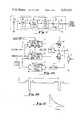
- FIG. 2Ais a block diagram showing a current control embodiment of the output stage of the system of this invention.
- FIG. 2Bis a curve depicting the timing of stimulus signals delivered by the system of this invention.
- FIG. 2Cis a curve illustrating the sampling of the polarization at the heart for use in the polarization feedback branch of the circuit of FIG. 2A.
- FIG. 1there is shown a block diagram illustrating the essential components of the pacing system utilizing this invention.
- the inventionis illustrated in terms of a demand pacer, the features of which are well known in the art.
- a sense amplifier 31detects the presence of a QRS signal, and connects a signal to a logic/control circuit 32 when a QRS has been sensed.
- a threshold tracking embodimentsuch as illustrated in U.S. Pat. No. 3,920,024
- amplifier 31must detect the evoked response which follows the stimulus in about 10 to 50 ms.
- the circuitry of block 32performs the normal logic functions of a demand pacer such as distinguishing a sensed natural QRS signal, timing out a refractory interval, etc.
- block 32For programmable pacemakers, stored information relative to pacing parameters and other program control features may be considered to be found in block 32. Also, block 32 suitably contains the desired circuitry for employing the evoked response information, e.g., tracking threshold. As illustrated, control signals may be transferred from block 32 to output 34, for controlling the output in accordance with programmed signals or for threshold tracking.
- Block 33is the basic timing generator, which establishes the rate at which the pacer delivers stimulus pulses in the absence of natural patient pulses. As is known in the art, if the timing generator times out on its own, meaning that a stimulus is to be delivered, the timing signal is connected to an output circuit 34.
- Output 34represents circuitry which is utilized in generating a desired output signal, commonly referred to as an output pulse, of desired value in terms of pulse width, voltage or current. As shown further in FIG. 1, the output 34 is connected to a pacing/sensing electrode which is the end of a pacing lead (not shown), which lead provides the necessary electrical connection between the pacemaker and the patient' s heart. An electrical path is illustrated between the output of circuit 34 and the input of sense amplifier 31. Further, power is provided, suitably by a lithium type battery or any other desired source, as illustrated at 35. For unipolar pacing systems, the terminal of source 35 shown as ground is generally connected to the case of the pacemaker, illustrated at 36.
- FIG. 2Athere is shown a block diagram of an embodiment of output circuit 34 which is based upon current control of the component pulses of the delivered stimulus signal.
- the term "stimulus signal”shall refer to the group or series of pulses delivered, the negative going pulse of which is the component which actually provides the stimulus.
- the term pulseis used in a general manner, it being understood that a pulse as actually generated and used within this invention is not confined to a sharp signal in the time domain, but may be a sloped, exponential or other form of nonlinear signal.
- the primary circuit components which generate the stimulus signalare the two current generators, namely the recharge current generator 40 and the stimulus generator 43.
- These two current generatorsare shown as ideal circuits and can be contructed in any conventional manner. They are suitably switchable on-off circuits, such that they can be turned on and off sharply, such as can be accomplished by putting a control voltage on the gate of a FET transistor or the like.
- recharge current generator 40is on; and stimulus current generator 43 is off, a current flows from V+ through the generator, through the capacitor 41 which charges up, and through the heart 42 to ground, thereby applying a positive polarity signal to the heart.
- stimulus current generator 43When stimulus current generator 43 is on, and recharge generator 40 is off, current flows up through heart 42 as seen in the drawing, through capacitor 41 (thereby discharging it) and down through current generator 43, delivering a negative pulse to the heart.
- the size of the negative going pulseis designed, in accordance with well known principles, to evoke stimulation of the heart.
- recharge generator 40is first triggered for a time T 1 to produce a first positive delivery of current to the heart, stimulus generator 43 is then turned on for a time T st to deliver the negative stimulating component, and then recharge generator 40 is turned on again for a time T 2 to deliver another recharge pulse.
- These three pulsespreferrably time contiguous as shown, constitute the total stimulus signal which is delivered periodically by the pacemaker when no natural heart signal is detected.
- recharge current control and timing circuit 52receives program information, suitably from block 32, for determining the ratio T 1 /T 2 , the amplitude of the recharge pulses, and the duration of each.
- stimulus current control and timing circuit 50controls the stimulus component delivered by current generator 43, and receives amplitude and duration program signals. Both circuits 52 and 50 receive basic timing signals from the timing generator 33, to determine when the series of pulses, or the overall stimulus signal is to be generated.
- the timing signalmay be connected from block 52 at the end of the first recharge pulse to trigger a stimulus pulse, and another timing signal may be connected from block 50 to 52 at the end of the stimulus pulse to trigger the second recharge signal.
- timing circuitryis well known in the art, and the time durations T 1 and T 2 may be provided conveniently by one-shot or monostable multi-vibrators or their equivalent, or other digital timing mechanisms well known in the art.
- FIG. 2Aprovides two or three feedback loops.
- Block 53is shown connected to point X, between the two current generators, which block measures the voltage at such point X at a predetermined time between stimulus signals.
- the circuitcan measure whether the net charge delivered through capacitor 41 during the preceeding impulse group is zero. If, due to improper balancing between positive and negative output currents, or for any other reason of instability, V X has been changed, an amplitude feedback signal is applied to block 52 to change the value of the recharge current. As long as the total charge delivered by the two recharge pulses and the stimulus charge is substantially zero, the voltage at point X, as sampled between stimulus signals, will not vary significantly.
- a second feedback branchis connected between the output at the heart and the recharge control circuit 52.
- the heart voltage V his sampled at a sample time shortly after termination of T 2 , to determine the polarization level.
- the polarization levelis compared to a reference at block 47, and an output signal connected to block 52 to change the ratio T 1 /T 2 of the recharge pulses for succeeding stimuli.
- the reference valuecan be related also to the stimulus duration (T st ) and/or amplitude. Changing the ratio of T 1 to T 2 changes the polarization decay characteristic, and by this means the residual polarization can be optimally reduced.
- a second branch 48 of this feedback loopsamples V h following the delivery of a backup pulse for a threshold tracking system. It is to be understood that for a threshold tracking system where a series of backup pulses is delivered until response is evoked, V h may be monitored following each of such backup pulses.
- the duration T 1 of the first recharge pulseis determined by the stimulus duration input, as well as the T 1 /T 2 ratio information.
- the amplitudeis determined by the program amplitude of the stimulus current, as well as the feedback through block 53.
- the stimulus pulse duration T stis determined by the stimulus duration information, while the stimulus amplitude is determined by the stimulus amplitude input.
- the second recharge pulse duration T 2is determined by the T 1 /T 2 ratio and by the stimulus duration input, while the amplitude is determined by the stimulus current input and by the feedback through block 53. It is important that the total charge of the two recharge pulses be substantially equal to the charge of the stimulus portion, such that the net charge delivered to the heart by the stimulus signal is substantially zero.
- T 1 plus T 2may be approximately 4 times T st , although this ratio may go up to 10 or more. It is, however, important that the second recharge pulse not be too long, since the evoked response can hardly be sensed until the second recharge pulse is terminated. Conversely, there is a limit in the amplitude of the two recharge pulses, since it has been found that if these pulses are made too high in amplitude this causes some reduction in the stimulation efficiency.
- the advantage of the circuit of FIG. 2Ais that the polarization is compensated for very accurately. This is an active system which measures the polarization, and forces adjustments through the feedback loops so as to reduce the polarization to a minimum.
- the disadvantagesare the use of two or more feedback systems, and the extra current consumption due to the complexity of the circuit.
- the 3 pulse arrangementprovides excellent improvement in reducing the detected polarization following stimulus
- improvementis accomplished by utilizing a positive recharge pulse prior to the negative stimulus pulse, even without a second recharge pulse.
- a recharge pulseis suitably no more than 10 ms, since a natural QRS can hardly be sensed during the recharge pulse.
- a second recharge pulseis utilized, it is preferably of short time duration, so that the evoked response can be sensed as quickly as possible.
Landscapes
- Health & Medical Sciences (AREA)
- Cardiology (AREA)
- Heart & Thoracic Surgery (AREA)
- Engineering & Computer Science (AREA)
- Biomedical Technology (AREA)
- Nuclear Medicine, Radiotherapy & Molecular Imaging (AREA)
- Radiology & Medical Imaging (AREA)
- Life Sciences & Earth Sciences (AREA)
- Animal Behavior & Ethology (AREA)
- General Health & Medical Sciences (AREA)
- Public Health (AREA)
- Veterinary Medicine (AREA)
- Electrotherapy Devices (AREA)
Abstract
Description
Claims (17)
Priority Applications (4)
| Application Number | Priority Date | Filing Date | Title |
|---|---|---|---|
| US06/231,882US4373531A (en) | 1979-04-16 | 1981-02-05 | Apparatus for physiological stimulation and detection of evoked response |
| EP19820200003EP0057944B1 (en) | 1981-02-05 | 1982-01-04 | Apparatus and method for physiological stimulation and detection of evoked response |
| AT82200003TATE9138T1 (en) | 1981-02-05 | 1982-01-04 | DEVICE AND METHOD FOR PHYSIOLOGICAL STIMULATION AND GENERATING THE EVOKED RESPONSE. |
| DE8282200003TDE3260610D1 (en) | 1981-02-05 | 1982-01-04 | Apparatus and method for physiological stimulation and detection of evoked response |
Applications Claiming Priority (2)
| Application Number | Priority Date | Filing Date | Title |
|---|---|---|---|
| US06/030,457US4305396A (en) | 1979-04-16 | 1979-04-16 | Rate adaptive pacemaker and method of cardiac pacing |
| US06/231,882US4373531A (en) | 1979-04-16 | 1981-02-05 | Apparatus for physiological stimulation and detection of evoked response |
Related Parent Applications (1)
| Application Number | Title | Priority Date | Filing Date |
|---|---|---|---|
| US06/030,457Continuation-In-PartUS4305396A (en) | 1979-04-16 | 1979-04-16 | Rate adaptive pacemaker and method of cardiac pacing |
Publications (1)
| Publication Number | Publication Date |
|---|---|
| US4373531Atrue US4373531A (en) | 1983-02-15 |
Family
ID=26706064
Family Applications (1)
| Application Number | Title | Priority Date | Filing Date |
|---|---|---|---|
| US06/231,882Expired - LifetimeUS4373531A (en) | 1979-04-16 | 1981-02-05 | Apparatus for physiological stimulation and detection of evoked response |
Country Status (1)
| Country | Link |
|---|---|
| US (1) | US4373531A (en) |
Cited By (57)
| Publication number | Priority date | Publication date | Assignee | Title |
|---|---|---|---|---|
| US4527568A (en)* | 1983-12-27 | 1985-07-09 | Vitafin N.V. | Dual chamber pacer with alternative rate adaptive means and method |
| DE3501169A1 (en)* | 1985-01-11 | 1986-07-17 | Biotronik Meß- und Therapiegeräte GmbH & Co Ingenieurbüro Berlin, 1000 Berlin | Heart pacemaker having means for recording signals from the heart |
| WO1986005698A1 (en)* | 1985-03-27 | 1986-10-09 | Siemens-Elema Ab | Stimulated heart interval measurement, adaptive pacer and method of operation |
| FR2602146A1 (en)* | 1986-08-01 | 1988-02-05 | Telectronics Nv | STIMULATING PULSE GENERATING CIRCUIT FOR CARDIAC STIMULATOR |
| US4903700A (en)* | 1986-08-01 | 1990-02-27 | Telectronics N.V. | Pacing pulse compensation |
| US5156149A (en)* | 1990-08-10 | 1992-10-20 | Medtronic, Inc. | Sensor for detecting cardiac depolarizations particularly adapted for use in a cardiac pacemaker |
| US5213098A (en)* | 1991-07-26 | 1993-05-25 | Medtronic, Inc. | Post-extrasystolic potentiation stimulation with physiologic sensor feedback |
| DE4231603A1 (en)* | 1992-09-17 | 1994-03-24 | Biotronik Mess & Therapieg | Pacemaker system |
| US5330512A (en)* | 1992-12-28 | 1994-07-19 | Cardiac Pacemakers, Inc. | Electrode charge-neutral sensing of evoked ECG |
| US5431693A (en)* | 1993-12-10 | 1995-07-11 | Intermedics, Inc. | Method of verifying capture of the heart by a pacemaker |
| US5443485A (en)* | 1993-09-08 | 1995-08-22 | Intermedics, Inc. | Apparatus and method for capture detection in a cardiac stimulator |
| WO1996023546A1 (en)* | 1995-02-02 | 1996-08-08 | Pacesetter, Inc. | Methods and apparatus for applying charge-balanced antiarrhythmia shocks |
| US5718720A (en)* | 1996-12-13 | 1998-02-17 | Sulzer Intermedics Inc. | Implantable cardiac stimulator with capture detection and impedance based autotuning of capture detection |
| US5735883A (en)* | 1996-12-13 | 1998-04-07 | Sulzer Intermedics Inc. | Implantable cardiac stimulator with impedance based autothreshold |
| US5766230A (en)* | 1996-11-06 | 1998-06-16 | Sulzer Intermedics Inc. | Pacemaker with intra-stimulus capture detection |
| US5843136A (en)* | 1997-11-24 | 1998-12-01 | Cardiac Pacemakers, Inc. | Pacing output circuitry for automatic capture threshold detection in cardiac pacing systems |
| US5861013A (en)* | 1997-04-29 | 1999-01-19 | Medtronic Inc. | Peak tracking capture detection circuit and method |
| US5871512A (en)* | 1997-04-29 | 1999-02-16 | Medtronic, Inc. | Microprocessor capture detection circuit and method |
| US5941903A (en)* | 1998-04-30 | 1999-08-24 | Cardiac Pacemakers, Inc | Pacemaker for detection of evoked response |
| US5954756A (en)* | 1998-04-09 | 1999-09-21 | Medtronic, Inc. | Microprocessor capture detection circuit and method |
| US5964787A (en)* | 1998-04-17 | 1999-10-12 | Vitatron Medical B.V. | Stimulus system with controllable switched capacitor output stage |
| WO1999062595A1 (en) | 1998-06-02 | 1999-12-09 | Cardiac Pacemakers, Inc. | Pacing output coupling capacitor for automatic capture threshold detection in cardiac pacing systems |
| US6067472A (en)* | 1997-03-12 | 2000-05-23 | Medtronic, Inc. | Pacemaker system and method with improved evoked response and repolarization signal detection |
| US6324425B1 (en)* | 1999-07-28 | 2001-11-27 | Medtronic, Inc., | Recharge circuitry for multi-site stimulation of body tissue |
| WO2002082982A1 (en)* | 2001-04-18 | 2002-10-24 | Cochlear Limited | Method and apparatus for measurement of evoked neural response |
| US6473649B1 (en) | 1999-12-22 | 2002-10-29 | Cardiac Pacemakers, Inc. | Rate management during automatic capture verification |
| US6587722B2 (en) | 2000-04-18 | 2003-07-01 | Sorin Biomedica Cardio S.P.A. | Device for determining the effectiveness of stimulation in an electrical heart stimulator |
| WO2004056420A1 (en) | 2002-12-20 | 2004-07-08 | Biotronik Gmbh & Co. Kg | Multi chamber capture detection |
| WO2004064632A1 (en)* | 2003-01-22 | 2004-08-05 | Sdgi Holdings, Inc. | Apparatus and method for intraoperative neural monitoring |
| US20040215275A1 (en)* | 2003-04-24 | 2004-10-28 | Vonk Bernardus F. M. | Intracardiac polarization signal stabilization |
| US20040215260A1 (en)* | 2003-04-23 | 2004-10-28 | Vonk Ben F.M. | Pulse generation techniques for implantable pulse generator systems |
| US20060089561A1 (en)* | 2002-09-04 | 2006-04-27 | Eder Helmut C | Method and apparatus for measurement of evoked neural response |
| US20060224199A1 (en)* | 2005-03-31 | 2006-10-05 | Zeijlemaker Volkert A | System for waveform stimulation compensating electrode polarization |
| US20060235332A1 (en)* | 2002-06-26 | 2006-10-19 | Smoorenburg Guido F | Parametric fitting of a cochlear implant |
| US20070027508A1 (en)* | 2005-08-01 | 2007-02-01 | Ebr Systems, Inc. | Efficiently delivering acoustic stimulation energy to tissue |
| US7184833B2 (en) | 2003-10-07 | 2007-02-27 | Medtronic, Inc. | Multiple pacing output channels |
| US20070112395A1 (en)* | 2005-10-31 | 2007-05-17 | Cochlear Limited | Automatic Measurement Of Neural Response Concurrent With Psychophysics Measurement Of Stimulating Device Recipient |
| US20070219599A1 (en)* | 2006-03-15 | 2007-09-20 | Cherik Bulkes | Composite Waveform Based Method and Apparatus for Animal Tissue Stimulation |
| US20080039904A1 (en)* | 2006-08-08 | 2008-02-14 | Cherik Bulkes | Intravascular implant system |
| US20080275531A1 (en)* | 2007-05-04 | 2008-11-06 | Cherik Bulkes | Implantable high efficiency digital stimulation device |
| US20080319508A1 (en)* | 2004-06-15 | 2008-12-25 | Cochlear Americas | Automatic Determination of the Threshold of an Evoked Neural Response |
| US20110082521A1 (en)* | 2004-06-15 | 2011-04-07 | Andrew Botros | Automatic measurement of an evoked neural response concurrent with an indication of a psychophysics reaction |
| WO2011115949A1 (en) | 2010-03-16 | 2011-09-22 | Medtronic Minimed, Inc. | Glucose sensor |
| US20110237967A1 (en)* | 2008-03-25 | 2011-09-29 | Ebr Systems, Inc. | Temporary electrode connection for wireless pacing systems |
| US8260430B2 (en) | 2010-07-01 | 2012-09-04 | Cochlear Limited | Stimulation channel selection for a stimulating medical device |
| WO2012154548A1 (en) | 2011-05-06 | 2012-11-15 | Medtronic Minimed, Inc. | Method and apparatus for continuous analyte monitoring |
| US8571675B2 (en) | 2006-04-21 | 2013-10-29 | Cochlear Limited | Determining operating parameters for a stimulating medical device |
| US9339657B2 (en) | 2011-05-05 | 2016-05-17 | Medtronic, Inc. | Selectively enabling a passive recharge cycle for an implantable cardiac stimulation device |
| US10080903B2 (en) | 2007-05-23 | 2018-09-25 | Ebr Systems, Inc. | Optimizing energy transmission in a leadless tissue stimulation system |
| DE102018118019B3 (en) | 2018-07-25 | 2019-10-10 | Inomed Medizintechnik Gmbh | Arrangement for delayed electrical charge compensation when administering stimulation current pulses and measuring electrical responses evoked by the pulses |
| US10744327B2 (en)* | 2015-12-11 | 2020-08-18 | Sorin Crm Sas | Active electrical nerve stimulation medical device, with automatic charge compensation control |
| US11026627B2 (en) | 2013-03-15 | 2021-06-08 | Cadwell Laboratories, Inc. | Surgical instruments for determining a location of a nerve during a procedure |
| US11177610B2 (en) | 2017-01-23 | 2021-11-16 | Cadwell Laboratories, ino. | Neuromonitoring connection system |
| US11253182B2 (en) | 2018-05-04 | 2022-02-22 | Cadwell Laboratories, Inc. | Apparatus and method for polyphasic multi-output constant-current and constant-voltage neurophysiological stimulation |
| US11443649B2 (en) | 2018-06-29 | 2022-09-13 | Cadwell Laboratories, Inc. | Neurophysiological monitoring training simulator |
| US11992339B2 (en) | 2018-05-04 | 2024-05-28 | Cadwell Laboratories, Inc. | Systems and methods for dynamic neurophysiological stimulation |
| US12350497B2 (en) | 2022-02-10 | 2025-07-08 | Ebr Systems, Inc. | Tissue stimulation systems and methods, such as for pacing cardiac tissue |
Citations (10)
| Publication number | Priority date | Publication date | Assignee | Title |
|---|---|---|---|---|
| US3563247A (en)* | 1968-03-14 | 1971-02-16 | Gen Electric | Bidirectional heart stimulator |
| US3683934A (en)* | 1968-08-31 | 1972-08-15 | Bohdan A Bukowiecki | Method and apparatus for providing synchronized stimulus and coupled stimulation from an implanted heart stimulator having a constant rhythm |
| US3835865A (en)* | 1970-07-10 | 1974-09-17 | Gen Electric | Body organ stimulator |
| US3845773A (en)* | 1972-07-07 | 1974-11-05 | Ass Rech Et D Entraide Cardiol | Cardiac stimulators |
| US3881493A (en)* | 1974-02-07 | 1975-05-06 | American Optical Corp | Synchronously reinforcing pacer |
| DE2520730A1 (en)* | 1974-05-16 | 1975-11-20 | Tesla Np | Output stage of heart-pacemaker - is modified to eliminate decay time of stimulus voltage and allow use of adaptive pacemaker |
| US3924641A (en)* | 1974-08-19 | 1975-12-09 | Axotronics Inc | Bi-phasic current stimulation system |
| US4055189A (en)* | 1975-05-19 | 1977-10-25 | Medalert Corporation | Condition monitoring pacer |
| US4114627A (en)* | 1976-12-14 | 1978-09-19 | American Hospital Supply Corporation | Cardiac pacer system and method with capture verification signal |
| US4170999A (en)* | 1977-08-19 | 1979-10-16 | Biotronik Mess- Und Therapiegerate Gmbh & Co. | Demand pacer having reduced recovery time |
- 1981
- 1981-02-05USUS06/231,882patent/US4373531A/ennot_activeExpired - Lifetime
Patent Citations (10)
| Publication number | Priority date | Publication date | Assignee | Title |
|---|---|---|---|---|
| US3563247A (en)* | 1968-03-14 | 1971-02-16 | Gen Electric | Bidirectional heart stimulator |
| US3683934A (en)* | 1968-08-31 | 1972-08-15 | Bohdan A Bukowiecki | Method and apparatus for providing synchronized stimulus and coupled stimulation from an implanted heart stimulator having a constant rhythm |
| US3835865A (en)* | 1970-07-10 | 1974-09-17 | Gen Electric | Body organ stimulator |
| US3845773A (en)* | 1972-07-07 | 1974-11-05 | Ass Rech Et D Entraide Cardiol | Cardiac stimulators |
| US3881493A (en)* | 1974-02-07 | 1975-05-06 | American Optical Corp | Synchronously reinforcing pacer |
| DE2520730A1 (en)* | 1974-05-16 | 1975-11-20 | Tesla Np | Output stage of heart-pacemaker - is modified to eliminate decay time of stimulus voltage and allow use of adaptive pacemaker |
| US3924641A (en)* | 1974-08-19 | 1975-12-09 | Axotronics Inc | Bi-phasic current stimulation system |
| US4055189A (en)* | 1975-05-19 | 1977-10-25 | Medalert Corporation | Condition monitoring pacer |
| US4114627A (en)* | 1976-12-14 | 1978-09-19 | American Hospital Supply Corporation | Cardiac pacer system and method with capture verification signal |
| US4170999A (en)* | 1977-08-19 | 1979-10-16 | Biotronik Mess- Und Therapiegerate Gmbh & Co. | Demand pacer having reduced recovery time |
Cited By (109)
| Publication number | Priority date | Publication date | Assignee | Title |
|---|---|---|---|---|
| US4527568A (en)* | 1983-12-27 | 1985-07-09 | Vitafin N.V. | Dual chamber pacer with alternative rate adaptive means and method |
| DE3501169A1 (en)* | 1985-01-11 | 1986-07-17 | Biotronik Meß- und Therapiegeräte GmbH & Co Ingenieurbüro Berlin, 1000 Berlin | Heart pacemaker having means for recording signals from the heart |
| WO1986005698A1 (en)* | 1985-03-27 | 1986-10-09 | Siemens-Elema Ab | Stimulated heart interval measurement, adaptive pacer and method of operation |
| FR2602146A1 (en)* | 1986-08-01 | 1988-02-05 | Telectronics Nv | STIMULATING PULSE GENERATING CIRCUIT FOR CARDIAC STIMULATOR |
| US4821724A (en)* | 1986-08-01 | 1989-04-18 | Telectronics N.V. | Pacing pulse compensation |
| US4903700A (en)* | 1986-08-01 | 1990-02-27 | Telectronics N.V. | Pacing pulse compensation |
| US5156149A (en)* | 1990-08-10 | 1992-10-20 | Medtronic, Inc. | Sensor for detecting cardiac depolarizations particularly adapted for use in a cardiac pacemaker |
| US5213098A (en)* | 1991-07-26 | 1993-05-25 | Medtronic, Inc. | Post-extrasystolic potentiation stimulation with physiologic sensor feedback |
| US5609611A (en)* | 1992-09-17 | 1997-03-11 | Biotronik Mess-Und Therapiegeraete Gmbh & Co. Ingenieurbuero Berlin | Pacemaker system with porous electrode and residual charge or after-potential reduction |
| DE4231603A1 (en)* | 1992-09-17 | 1994-03-24 | Biotronik Mess & Therapieg | Pacemaker system |
| US5330512A (en)* | 1992-12-28 | 1994-07-19 | Cardiac Pacemakers, Inc. | Electrode charge-neutral sensing of evoked ECG |
| US5443485A (en)* | 1993-09-08 | 1995-08-22 | Intermedics, Inc. | Apparatus and method for capture detection in a cardiac stimulator |
| US5431693A (en)* | 1993-12-10 | 1995-07-11 | Intermedics, Inc. | Method of verifying capture of the heart by a pacemaker |
| US5601608A (en)* | 1995-02-02 | 1997-02-11 | Pacesetter, Inc. | Methods and apparatus for applying charge-balanced antiarrhythmia shocks |
| WO1996023546A1 (en)* | 1995-02-02 | 1996-08-08 | Pacesetter, Inc. | Methods and apparatus for applying charge-balanced antiarrhythmia shocks |
| US5766230A (en)* | 1996-11-06 | 1998-06-16 | Sulzer Intermedics Inc. | Pacemaker with intra-stimulus capture detection |
| US5718720A (en)* | 1996-12-13 | 1998-02-17 | Sulzer Intermedics Inc. | Implantable cardiac stimulator with capture detection and impedance based autotuning of capture detection |
| US5735883A (en)* | 1996-12-13 | 1998-04-07 | Sulzer Intermedics Inc. | Implantable cardiac stimulator with impedance based autothreshold |
| WO1998025672A1 (en) | 1996-12-13 | 1998-06-18 | Intermedics Inc. | Implantable cardiac stimulator with capture detection and impedance based autotuning of capture detection |
| WO1998025671A1 (en) | 1996-12-13 | 1998-06-18 | Intermedics Inc. | Implantable cardiac stimulator with impedance based autothreshold |
| US6067472A (en)* | 1997-03-12 | 2000-05-23 | Medtronic, Inc. | Pacemaker system and method with improved evoked response and repolarization signal detection |
| US6144881A (en)* | 1997-04-29 | 2000-11-07 | Medtronic, Inc. | Capture detection circuit for pulses and physiologic signals |
| US6134473A (en)* | 1997-04-29 | 2000-10-17 | Medtronic, Inc. | Microprocessor capture detection circuit and method |
| US5873898A (en)* | 1997-04-29 | 1999-02-23 | Medtronic, Inc. | Microprocessor capture detection circuit and method |
| US5871512A (en)* | 1997-04-29 | 1999-02-16 | Medtronic, Inc. | Microprocessor capture detection circuit and method |
| US5861013A (en)* | 1997-04-29 | 1999-01-19 | Medtronic Inc. | Peak tracking capture detection circuit and method |
| WO1999026694A1 (en)* | 1997-11-24 | 1999-06-03 | Cardiac Pacemakers, Inc. | Pacing output circuitry for automatic capture threshold detection in cardiac pacing systems |
| US5843136A (en)* | 1997-11-24 | 1998-12-01 | Cardiac Pacemakers, Inc. | Pacing output circuitry for automatic capture threshold detection in cardiac pacing systems |
| US6044296A (en)* | 1997-11-24 | 2000-03-28 | Cardiac Pacemakers, Inc. | Pacing output coupling capacitor for automatic capture threshold detection in cardiac pacing systems |
| US5954756A (en)* | 1998-04-09 | 1999-09-21 | Medtronic, Inc. | Microprocessor capture detection circuit and method |
| US5964787A (en)* | 1998-04-17 | 1999-10-12 | Vitatron Medical B.V. | Stimulus system with controllable switched capacitor output stage |
| US5941903A (en)* | 1998-04-30 | 1999-08-24 | Cardiac Pacemakers, Inc | Pacemaker for detection of evoked response |
| WO1999062595A1 (en) | 1998-06-02 | 1999-12-09 | Cardiac Pacemakers, Inc. | Pacing output coupling capacitor for automatic capture threshold detection in cardiac pacing systems |
| US6324425B1 (en)* | 1999-07-28 | 2001-11-27 | Medtronic, Inc., | Recharge circuitry for multi-site stimulation of body tissue |
| US6473649B1 (en) | 1999-12-22 | 2002-10-29 | Cardiac Pacemakers, Inc. | Rate management during automatic capture verification |
| US6587722B2 (en) | 2000-04-18 | 2003-07-01 | Sorin Biomedica Cardio S.P.A. | Device for determining the effectiveness of stimulation in an electrical heart stimulator |
| US8454529B2 (en) | 2001-04-18 | 2013-06-04 | Cochlear Limited | Minimization of electrical stimulus artifact during measurement of evoked neural response |
| US20070225767A1 (en)* | 2001-04-18 | 2007-09-27 | Cochlear Limited | Minimization of electrical stimulus artifact during measurement of evoked neural response |
| US20050101878A1 (en)* | 2001-04-18 | 2005-05-12 | Daly Christopher N. | Method and apparatus for measurement of evoked neural response |
| WO2002082982A1 (en)* | 2001-04-18 | 2002-10-24 | Cochlear Limited | Method and apparatus for measurement of evoked neural response |
| US20060235332A1 (en)* | 2002-06-26 | 2006-10-19 | Smoorenburg Guido F | Parametric fitting of a cochlear implant |
| US20090043359A1 (en)* | 2002-06-26 | 2009-02-12 | Cochlear Limited | Perception-based parametric fitting of a prosthetic hearing device |
| US8401656B2 (en) | 2002-06-26 | 2013-03-19 | Cochlear Limited | Perception-based parametric fitting of a prosthetic hearing device |
| US8694113B2 (en) | 2002-06-26 | 2014-04-08 | Cochlear Limited | Parametric fitting of a cochlear implant |
| US7809445B2 (en) | 2002-09-04 | 2010-10-05 | Cochlear Limited | Measurement of evoked neural response |
| US20060089561A1 (en)* | 2002-09-04 | 2006-04-27 | Eder Helmut C | Method and apparatus for measurement of evoked neural response |
| US20060136003A1 (en)* | 2002-12-20 | 2006-06-22 | Lee Hudson | Multi chamber capture detection |
| WO2004056420A1 (en) | 2002-12-20 | 2004-07-08 | Biotronik Gmbh & Co. Kg | Multi chamber capture detection |
| US7474922B2 (en) | 2002-12-20 | 2009-01-06 | Biotronik Gmbh & Co. Kg | Multi chamber capture detection |
| WO2004064632A1 (en)* | 2003-01-22 | 2004-08-05 | Sdgi Holdings, Inc. | Apparatus and method for intraoperative neural monitoring |
| US7216001B2 (en) | 2003-01-22 | 2007-05-08 | Medtronic Xomed, Inc. | Apparatus for intraoperative neural monitoring |
| US20050085743A1 (en)* | 2003-01-22 | 2005-04-21 | Hacker David C. | Apparatus and method for intraoperative neural monitoring |
| US20040215260A1 (en)* | 2003-04-23 | 2004-10-28 | Vonk Ben F.M. | Pulse generation techniques for implantable pulse generator systems |
| US8340762B2 (en)* | 2003-04-23 | 2012-12-25 | Medtronic, Inc. | Pulse generation techniques for implantable pulse generator systems |
| US20040215275A1 (en)* | 2003-04-24 | 2004-10-28 | Vonk Bernardus F. M. | Intracardiac polarization signal stabilization |
| US7363078B2 (en) | 2003-04-24 | 2008-04-22 | Medtronic, Inc. | Intracardiac polarization signal stabilization |
| US7184833B2 (en) | 2003-10-07 | 2007-02-27 | Medtronic, Inc. | Multiple pacing output channels |
| US8965520B2 (en) | 2004-06-15 | 2015-02-24 | Cochlear Limited | Automatic determination of the threshold of an evoked neural response |
| US20080319508A1 (en)* | 2004-06-15 | 2008-12-25 | Cochlear Americas | Automatic Determination of the Threshold of an Evoked Neural Response |
| US8190268B2 (en) | 2004-06-15 | 2012-05-29 | Cochlear Limited | Automatic measurement of an evoked neural response concurrent with an indication of a psychophysics reaction |
| US10449357B2 (en) | 2004-06-15 | 2019-10-22 | Cochlear Limited | Automatic determination of the threshold of an evoked neural response |
| US9744356B2 (en) | 2004-06-15 | 2017-08-29 | Cochlear Limited | Automatic determination of the threshold of an evoked neural response |
| US20110082521A1 (en)* | 2004-06-15 | 2011-04-07 | Andrew Botros | Automatic measurement of an evoked neural response concurrent with an indication of a psychophysics reaction |
| US7577480B2 (en)* | 2005-03-31 | 2009-08-18 | Medtronic, Inc. | System for waveform stimulation compensating electrode polarization |
| US20100016912A1 (en)* | 2005-03-31 | 2010-01-21 | Medtronic, Inc. | System for waveform stimulation compensating electrode polarization |
| US20060224199A1 (en)* | 2005-03-31 | 2006-10-05 | Zeijlemaker Volkert A | System for waveform stimulation compensating electrode polarization |
| US8260418B2 (en)* | 2005-03-31 | 2012-09-04 | Medtronic, Inc. | System for waveform stimulation compensating electrode polarization |
| US9014803B2 (en) | 2005-08-01 | 2015-04-21 | Ebr Systems, Inc. | Efficiently delivering acoustic stimulation energy to tissue |
| US8634908B2 (en) | 2005-08-01 | 2014-01-21 | Ebr Systems, Inc. | Efficiently delivering acoustic stimulation energy to tissue |
| US9616235B2 (en) | 2005-08-01 | 2017-04-11 | Ebr Systems, Inc. | Efficiently delivering acoustic stimulation energy to tissue |
| US10576287B2 (en) | 2005-08-01 | 2020-03-03 | Ebr Systems, Inc. | Efficiently delivering acoustic stimulation energy to tissue |
| US9855429B2 (en) | 2005-08-01 | 2018-01-02 | Ebr Systems, Inc. | Efficiently delivering acoustic stimulation energy to tissue |
| US20070027508A1 (en)* | 2005-08-01 | 2007-02-01 | Ebr Systems, Inc. | Efficiently delivering acoustic stimulation energy to tissue |
| WO2007016581A2 (en) | 2005-08-01 | 2007-02-08 | Ebr Systems, Inc. | Efficiently delivering acoustic stimulation energy to tissue |
| US8019432B2 (en) | 2005-10-31 | 2011-09-13 | Cochlear Limited | Provision of stimulus components having variable perceptability to stimulating device recipient |
| US20070112395A1 (en)* | 2005-10-31 | 2007-05-17 | Cochlear Limited | Automatic Measurement Of Neural Response Concurrent With Psychophysics Measurement Of Stimulating Device Recipient |
| US7801617B2 (en) | 2005-10-31 | 2010-09-21 | Cochlear Limited | Automatic measurement of neural response concurrent with psychophysics measurement of stimulating device recipient |
| US20070219599A1 (en)* | 2006-03-15 | 2007-09-20 | Cherik Bulkes | Composite Waveform Based Method and Apparatus for Animal Tissue Stimulation |
| WO2007109076A1 (en)* | 2006-03-15 | 2007-09-27 | Cherik Bulkes | Composite waveform based method and apparatus for animal tissue stimulation |
| US7881804B2 (en) | 2006-03-15 | 2011-02-01 | Kenergy, Inc. | Composite waveform based method and apparatus for animal tissue stimulation |
| US8571675B2 (en) | 2006-04-21 | 2013-10-29 | Cochlear Limited | Determining operating parameters for a stimulating medical device |
| US20080039904A1 (en)* | 2006-08-08 | 2008-02-14 | Cherik Bulkes | Intravascular implant system |
| US20080275531A1 (en)* | 2007-05-04 | 2008-11-06 | Cherik Bulkes | Implantable high efficiency digital stimulation device |
| US10456588B2 (en) | 2007-05-23 | 2019-10-29 | Ebr Systems, Inc. | Optimizing energy transmission in a leadless tissue stimulation system |
| US10080903B2 (en) | 2007-05-23 | 2018-09-25 | Ebr Systems, Inc. | Optimizing energy transmission in a leadless tissue stimulation system |
| US11452879B2 (en) | 2007-05-23 | 2022-09-27 | Ebr Systems, Inc. | Optimizing energy transmission in a leadless tissue stimulation system |
| US9907968B2 (en) | 2008-03-25 | 2018-03-06 | Ebr Systems, Inc. | Temporary electrode connection for wireless pacing systems |
| US10688307B2 (en) | 2008-03-25 | 2020-06-23 | Ebr Systems, Inc. | Temporary electrode connection for wireless pacing systems |
| US9283392B2 (en) | 2008-03-25 | 2016-03-15 | Ebr Systems, Inc. | Temporary electrode connection for wireless pacing systems |
| US11752352B2 (en) | 2008-03-25 | 2023-09-12 | Ebr Systems, Inc. | Temporary electrode connection for wireless pacing systems |
| US20110237967A1 (en)* | 2008-03-25 | 2011-09-29 | Ebr Systems, Inc. | Temporary electrode connection for wireless pacing systems |
| WO2011115949A1 (en) | 2010-03-16 | 2011-09-22 | Medtronic Minimed, Inc. | Glucose sensor |
| US10448872B2 (en) | 2010-03-16 | 2019-10-22 | Medtronic Minimed, Inc. | Analyte sensor apparatuses having improved electrode configurations and methods for making and using them |
| US8260430B2 (en) | 2010-07-01 | 2012-09-04 | Cochlear Limited | Stimulation channel selection for a stimulating medical device |
| US9339657B2 (en) | 2011-05-05 | 2016-05-17 | Medtronic, Inc. | Selectively enabling a passive recharge cycle for an implantable cardiac stimulation device |
| US9008744B2 (en) | 2011-05-06 | 2015-04-14 | Medtronic Minimed, Inc. | Method and apparatus for continuous analyte monitoring |
| WO2012154548A1 (en) | 2011-05-06 | 2012-11-15 | Medtronic Minimed, Inc. | Method and apparatus for continuous analyte monitoring |
| US11026627B2 (en) | 2013-03-15 | 2021-06-08 | Cadwell Laboratories, Inc. | Surgical instruments for determining a location of a nerve during a procedure |
| US12178606B2 (en) | 2013-03-15 | 2024-12-31 | Cadwell Laboratories, Inc. | Neuromonitoring systems and methods |
| US10744327B2 (en)* | 2015-12-11 | 2020-08-18 | Sorin Crm Sas | Active electrical nerve stimulation medical device, with automatic charge compensation control |
| US11949188B2 (en) | 2017-01-23 | 2024-04-02 | Cadwell Laboratories, Inc. | Methods for concurrently forming multiple electrical connections in a neuro-monitoring system |
| US11177610B2 (en) | 2017-01-23 | 2021-11-16 | Cadwell Laboratories, ino. | Neuromonitoring connection system |
| US11992339B2 (en) | 2018-05-04 | 2024-05-28 | Cadwell Laboratories, Inc. | Systems and methods for dynamic neurophysiological stimulation |
| US11998338B2 (en) | 2018-05-04 | 2024-06-04 | Cadwell Laboratories, Inc. | Systems and methods for dynamically switching output port cathode and anode designations |
| US11253182B2 (en) | 2018-05-04 | 2022-02-22 | Cadwell Laboratories, Inc. | Apparatus and method for polyphasic multi-output constant-current and constant-voltage neurophysiological stimulation |
| US11978360B2 (en) | 2018-06-29 | 2024-05-07 | Cadwell Laboratories, Inc. | Systems and methods for neurophysiological simulation |
| US11443649B2 (en) | 2018-06-29 | 2022-09-13 | Cadwell Laboratories, Inc. | Neurophysiological monitoring training simulator |
| DE102018118019B3 (en) | 2018-07-25 | 2019-10-10 | Inomed Medizintechnik Gmbh | Arrangement for delayed electrical charge compensation when administering stimulation current pulses and measuring electrical responses evoked by the pulses |
| US12350497B2 (en) | 2022-02-10 | 2025-07-08 | Ebr Systems, Inc. | Tissue stimulation systems and methods, such as for pacing cardiac tissue |
Similar Documents
| Publication | Publication Date | Title |
|---|---|---|
| US4373531A (en) | Apparatus for physiological stimulation and detection of evoked response | |
| US4343312A (en) | Pacemaker output circuit | |
| US4406286A (en) | Fast recharge output circuit | |
| US4827934A (en) | Sensing margin detectors for implantable electromedical devices | |
| US4066086A (en) | Programmable body stimulator | |
| US4340062A (en) | Body stimulator having selectable stimulation energy levels | |
| US5137021A (en) | Lead current measurement circuit | |
| EP0089014B1 (en) | Physiological implantable cardiac pacemaker in which the stimulation rate is regulated by the respiration rate of the patient | |
| US3835865A (en) | Body organ stimulator | |
| US6169921B1 (en) | Autocapture determination for an implantable cardioverter defibrillator | |
| US4476868A (en) | Body stimulator output circuit | |
| US5843136A (en) | Pacing output circuitry for automatic capture threshold detection in cardiac pacing systems | |
| US4595009A (en) | Protection circuit for implantable cardioverter | |
| US7873415B2 (en) | Cardiac rhythm management system and method | |
| US4114627A (en) | Cardiac pacer system and method with capture verification signal | |
| JP2809511B2 (en) | Cardiac pacemaker with programmable output pulse amplitude | |
| US3618615A (en) | Self checking cardiac pacemaker | |
| US4091817A (en) | P-Wave control, R-wave inhibited ventricular stimulation device | |
| US5964787A (en) | Stimulus system with controllable switched capacitor output stage | |
| US3757792A (en) | Automatic threshold compensating demand pacemaker | |
| GB1590100A (en) | Heart stimulation devices | |
| EP0838234B1 (en) | Implantable stimulating device | |
| US5165404A (en) | Biological tissue stimulation device with control means for determining stimulation sensitivity calculation timing | |
| US6104954A (en) | High frequency lead testing apparatus in an implantable defibrillator | |
| US5941903A (en) | Pacemaker for detection of evoked response |
Legal Events
| Date | Code | Title | Description |
|---|---|---|---|
| AS | Assignment | Owner name:VITATRON MEDICAL B.V., DIEREN THE NETHERLANDS, A C Free format text:ASSIGNMENT OF ASSIGNORS INTEREST.;ASSIGNORS:WITTKAMPF FREDERIK H.M.;MENSINK KORNELIS A.;BROUWER HENDRIK L.;REEL/FRAME:003844/0993 Effective date:19810123 | |
| AS | Assignment | Owner name:VITAFIN N.V., CURACAO A CORP. OF NETHERLANDS ANTIL Free format text:ASSIGNMENT OF ASSIGNORS INTEREST.;ASSIGNOR:VITATRON MEDICAL B.V.;REEL/FRAME:003942/0286 Effective date:19811211 Owner name:VITAFIN N.V., CURACAO A CORP. OF NETHERLANDS ANTIL Free format text:ASSIGNMENT OF ASSIGNORS INTEREST;ASSIGNOR:VITATRON MEDICAL B.V.;REEL/FRAME:003942/0286 Effective date:19811211 | |
| STCF | Information on status: patent grant | Free format text:PATENTED CASE | |
| MAFP | Maintenance fee payment | Free format text:PAYMENT OF MAINTENANCE FEE, 4TH YEAR, PL 96-517 (ORIGINAL EVENT CODE: M170); ENTITY STATUS OF PATENT OWNER: LARGE ENTITY Year of fee payment:4 | |
| AS | Assignment | Owner name:VITATRON MEDICAL B.V., A CORP. OF THE NETHERLANDS, Free format text:ASSIGNMENT OF ASSIGNORS INTEREST.;ASSIGNOR:VITAFIN N.V., A CORP. OF NETHERLANDS;REEL/FRAME:005080/0827 Effective date:19890410 | |
| MAFP | Maintenance fee payment | Free format text:PAYMENT OF MAINTENANCE FEE, 8TH YEAR, PL 96-517 (ORIGINAL EVENT CODE: M171); ENTITY STATUS OF PATENT OWNER: LARGE ENTITY Year of fee payment:8 | |
| FEPP | Fee payment procedure | Free format text:PAYOR NUMBER ASSIGNED (ORIGINAL EVENT CODE: ASPN); ENTITY STATUS OF PATENT OWNER: LARGE ENTITY | |
| MAFP | Maintenance fee payment | Free format text:PAYMENT OF MAINTENANCE FEE, 12TH YEAR, LARGE ENTITY (ORIGINAL EVENT CODE: M185); ENTITY STATUS OF PATENT OWNER: LARGE ENTITY Year of fee payment:12 |