US4371385A - Deaerating liquid - Google Patents
Deaerating liquidDownload PDFInfo
- Publication number
- US4371385A US4371385AUS06/258,423US25842381AUS4371385AUS 4371385 AUS4371385 AUS 4371385AUS 25842381 AUS25842381 AUS 25842381AUS 4371385 AUS4371385 AUS 4371385A
- Authority
- US
- United States
- Prior art keywords
- liquid
- outlet
- chamber means
- deaeration chamber
- pump
- Prior art date
- Legal status (The legal status is an assumption and is not a legal conclusion. Google has not performed a legal analysis and makes no representation as to the accuracy of the status listed.)
- Expired - Lifetime
Links
- 239000007788liquidSubstances0.000titleclaimsabstractdescription57
- 238000011144upstream manufacturingMethods0.000claimsabstractdescription8
- 238000006073displacement reactionMethods0.000claimsabstractdescription5
- XLYOFNOQVPJJNP-UHFFFAOYSA-NwaterSubstancesOXLYOFNOQVPJJNP-UHFFFAOYSA-N0.000claimsdescription31
- 239000007789gasSubstances0.000claimsdescription11
- 239000000463materialSubstances0.000claimsdescription5
- 230000006911nucleationEffects0.000claimsdescription5
- 238000010899nucleationMethods0.000claimsdescription5
- 230000015572biosynthetic processEffects0.000claimsdescription4
- 238000005086pumpingMethods0.000claimsdescription3
- 238000000108ultra-filtrationMethods0.000description58
- WSFSSNUMVMOOMR-UHFFFAOYSA-NFormaldehydeChemical compoundO=CWSFSSNUMVMOOMR-UHFFFAOYSA-N0.000description19
- 239000012530fluidSubstances0.000description15
- 238000005259measurementMethods0.000description14
- 238000004140cleaningMethods0.000description12
- 230000000249desinfective effectEffects0.000description11
- 238000000502dialysisMethods0.000description11
- 239000000126substanceSubstances0.000description11
- 239000007844bleaching agentSubstances0.000description8
- 239000012528membraneSubstances0.000description8
- 239000008280bloodSubstances0.000description6
- 210000004369bloodAnatomy0.000description6
- 230000003213activating effectEffects0.000description5
- 230000036772blood pressureEffects0.000description5
- 239000000645desinfectantSubstances0.000description5
- 230000037361pathwayEffects0.000description5
- 239000004743PolypropyleneSubstances0.000description4
- 238000012512characterization methodMethods0.000description4
- 239000012141concentrateSubstances0.000description4
- 238000000034methodMethods0.000description4
- 230000003287optical effectEffects0.000description4
- -1polypropylenePolymers0.000description4
- 229920001155polypropylenePolymers0.000description4
- 238000002360preparation methodMethods0.000description4
- 239000003381stabilizerSubstances0.000description4
- 230000008859changeEffects0.000description3
- 230000007423decreaseEffects0.000description3
- 238000012935AveragingMethods0.000description2
- 230000003247decreasing effectEffects0.000description2
- 238000007872degassingMethods0.000description2
- 238000010586diagramMethods0.000description2
- 230000007246mechanismEffects0.000description2
- 206010053567CoagulopathiesDiseases0.000description1
- 239000005708Sodium hypochloriteSubstances0.000description1
- 238000004061bleachingMethods0.000description1
- 238000004364calculation methodMethods0.000description1
- 230000035602clottingEffects0.000description1
- 230000002016colloidosmotic effectEffects0.000description1
- 238000010276constructionMethods0.000description1
- 230000001419dependent effectEffects0.000description1
- 238000011049fillingMethods0.000description1
- 238000011010flushing procedureMethods0.000description1
- 239000008098formaldehyde solutionSubstances0.000description1
- 238000003780insertionMethods0.000description1
- 230000037431insertionEffects0.000description1
- 230000003993interactionEffects0.000description1
- 238000012886linear functionMethods0.000description1
- 239000007791liquid phaseSubstances0.000description1
- 239000006193liquid solutionSubstances0.000description1
- 230000013011matingEffects0.000description1
- WSFSSNUMVMOOMR-NJFSPNSNSA-NmethanoneChemical compoundO=[14CH2]WSFSSNUMVMOOMR-NJFSPNSNSA-N0.000description1
- 238000002156mixingMethods0.000description1
- 230000003204osmotic effectEffects0.000description1
- 230000000737periodic effectEffects0.000description1
- 102000004169proteins and genesHuman genes0.000description1
- 108090000623proteins and genesProteins0.000description1
- 238000010926purgeMethods0.000description1
- 230000004044responseEffects0.000description1
- SUKJFIGYRHOWBL-UHFFFAOYSA-Nsodium hypochloriteChemical compound[Na+].Cl[O-]SUKJFIGYRHOWBL-UHFFFAOYSA-N0.000description1
- 230000000087stabilizing effectEffects0.000description1
- 208000024891symptomDiseases0.000description1
- 230000002123temporal effectEffects0.000description1
- 238000012546transferMethods0.000description1
Images


Classifications
- B—PERFORMING OPERATIONS; TRANSPORTING
- B01—PHYSICAL OR CHEMICAL PROCESSES OR APPARATUS IN GENERAL
- B01D—SEPARATION
- B01D19/00—Degasification of liquids
- B01D19/0063—Regulation, control including valves and floats
- A—HUMAN NECESSITIES
- A61—MEDICAL OR VETERINARY SCIENCE; HYGIENE
- A61M—DEVICES FOR INTRODUCING MEDIA INTO, OR ONTO, THE BODY; DEVICES FOR TRANSDUCING BODY MEDIA OR FOR TAKING MEDIA FROM THE BODY; DEVICES FOR PRODUCING OR ENDING SLEEP OR STUPOR
- A61M1/00—Suction or pumping devices for medical purposes; Devices for carrying-off, for treatment of, or for carrying-over, body-liquids; Drainage systems
- A61M1/14—Dialysis systems; Artificial kidneys; Blood oxygenators ; Reciprocating systems for treatment of body fluids, e.g. single needle systems for hemofiltration or pheresis
- A61M1/16—Dialysis systems; Artificial kidneys; Blood oxygenators ; Reciprocating systems for treatment of body fluids, e.g. single needle systems for hemofiltration or pheresis with membranes
- A61M1/1654—Dialysates therefor
- A61M1/1656—Apparatus for preparing dialysates
- A61M1/1658—Degasification
- B—PERFORMING OPERATIONS; TRANSPORTING
- B01—PHYSICAL OR CHEMICAL PROCESSES OR APPARATUS IN GENERAL
- B01D—SEPARATION
- B01D61/00—Processes of separation using semi-permeable membranes, e.g. dialysis, osmosis or ultrafiltration; Apparatus, accessories or auxiliary operations specially adapted therefor
- B01D61/24—Dialysis ; Membrane extraction
- B01D61/30—Accessories; Auxiliary operation
- A—HUMAN NECESSITIES
- A61—MEDICAL OR VETERINARY SCIENCE; HYGIENE
- A61M—DEVICES FOR INTRODUCING MEDIA INTO, OR ONTO, THE BODY; DEVICES FOR TRANSDUCING BODY MEDIA OR FOR TAKING MEDIA FROM THE BODY; DEVICES FOR PRODUCING OR ENDING SLEEP OR STUPOR
- A61M2205/00—General characteristics of the apparatus
- A61M2205/14—Detection of the presence or absence of a tube, a connector or a container in an apparatus
- A—HUMAN NECESSITIES
- A61—MEDICAL OR VETERINARY SCIENCE; HYGIENE
- A61M—DEVICES FOR INTRODUCING MEDIA INTO, OR ONTO, THE BODY; DEVICES FOR TRANSDUCING BODY MEDIA OR FOR TAKING MEDIA FROM THE BODY; DEVICES FOR PRODUCING OR ENDING SLEEP OR STUPOR
- A61M2205/00—General characteristics of the apparatus
- A61M2205/60—General characteristics of the apparatus with identification means
- A61M2205/6063—Optical identification systems
- A61M2205/6081—Colour codes
- B—PERFORMING OPERATIONS; TRANSPORTING
- B01—PHYSICAL OR CHEMICAL PROCESSES OR APPARATUS IN GENERAL
- B01D—SEPARATION
- B01D2311/00—Details relating to membrane separation process operations and control
- B01D2311/02—Specific process operations before starting the membrane separation process
- Y—GENERAL TAGGING OF NEW TECHNOLOGICAL DEVELOPMENTS; GENERAL TAGGING OF CROSS-SECTIONAL TECHNOLOGIES SPANNING OVER SEVERAL SECTIONS OF THE IPC; TECHNICAL SUBJECTS COVERED BY FORMER USPC CROSS-REFERENCE ART COLLECTIONS [XRACs] AND DIGESTS
- Y10—TECHNICAL SUBJECTS COVERED BY FORMER USPC
- Y10S—TECHNICAL SUBJECTS COVERED BY FORMER USPC CROSS-REFERENCE ART COLLECTIONS [XRACs] AND DIGESTS
- Y10S210/00—Liquid purification or separation
- Y10S210/929—Hemoultrafiltrate volume measurement or control processes
Definitions
- the inventionrelates to apparatus for deaerating liquids.
- a heateris used in the supply line upstream of the deaeration chamber to increase the temperature of the liquid and lower the solubility of dissolved gas;
- a nucleation chamber with material therein providing sites for bubble formationis provided upstream of the deaeration chamber; material is placed within the deaeration chamber to provide sites at which the air bubbles will be detained and increase in size;
- a second deaeration chamberis placed downstream of the pump for removal of dissolved gases volatizing downstream of the first deaeration chamber;
- the liquidis water, concentrated dialysate solution is mixed with the water exiting from the second deaeration chamber, and the combined flowstream passes through a third deaeration chamber to remove gas bubbles forming in the concentrate flow line;
- the low pressure sinkis a second pump; and the liquid outlet of the third deaeration chamber is connected to a dialyer, the dialysate return line of which is also connected to the inlet of the second pump.
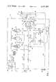
- FIG. 1is a diagrammatic representation of a dialysate preparation supply and control system according to the invention.
- FIG. 2is an elevation, partially broken away, of a variable restriction valve used in the FIG. 1 system.
- FIG. 3is a side elevation, partially broken away, of the FIG. 2 device.
- FIG. 4is an elevation of an external fluid port for the FIG. 1 system.
- FIG. 5is a side elevation of an external fluid connector.
- FIG. 6is a vertical sectional view, taken at 6--6 of FIG. 5, of external fluid connectors.
- FIG. 7is a diagrammatic representation of a cleaning, disinfecting, and rinsing subsystem of the FIG. 1 system.
- FIG. 8is a plan view of a display and control panel of the FIG. 1 system.
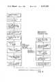
- FIG. 9is a flow diagram describing a method of controlling ultrafiltration in the FIG. 1 system.
- FIGS. 10-12are flow diagrams describing methods of rinsing, cleaning, and disinfecting the FIG. 1 system.
- a dialysate preparation, supply and control system 10connected to externally located dialyzer 12, venous blood pressure transducer 14, and dialysate concentrate source 18.
- Port 16is for external connection to a source of water, and port 20 is for draining used dialysate.
- water inlet valve 17which is normally open to allow flow of water through the machine, whenever the machine is turned on.
- Valve 17is connected to flow control restrictor 22, which only allows approximately 600 cc/min flow, and this is connected by line 23 to 1200 watt heater 24, which heats water to approximately 38.0° C. via a temperature control circuit of a type well known in the art.
- Rinse port 21is connected to the flow line 23.
- Heater 24is connected to nucleation chamber 26, containing chopped polypropylene netting (pieces less than approximately 1/8 inch in size, sold under Vexar trademark) between two filters in the chamber, and chamber 26 is connected in series to deaeration chambers 28 and 30, and air-bypass/stabilizer chamber 32.
- Chamber 28contains crumpled polypropylene netting. Gas separated from the liquid in the deaeration chambers, and gas that may have been admitted via the concentrate inlet line 41, is removed via lines 34, 36, 38, and the deaerated liquid is removed from the bottoms of the chambers.
- Flow restriction orifice 39 and positive displacement pump 40are located between the liquid outlet of chamber 28 and the liquid inlet of chamber 30. Concentrated dialysate solution from source 18 is pumped through line 41 by pump 42 and mixes with deaerated water at junction 44 between deaeration chamber 30 and air-bypass/stabilizer chamber 32.
- valve 48The liquid outlet of chamber 32 is connected by line 46 to two-position, four-connection valve 48.
- the other lines connected to valve 48are dialyzer supply line 50, dialyzer return line 52 and dialysate drain line 54.
- valve 48is shown in a dialysate supply mode with dialysate line 46 connected to supply line 50, and dialysate return line 52 connected to drain line 54.
- the linesare connected to the flow paths indicated in the bottom half of the schematic representation of valve 48.
- line 46is connected directly to line 54, and lines 50 and 52 are blocked, thereby forcing any liquid flowing out of the dialyzer through line 55 to go through line 56 connected to the dialysate return line 52 and line 55 at junction 58.
- Dialysate pressure in the membrane device 12, P dis sensed by pressure transducer 59, which is connected to hydraulically average the dialysate pressure immediately before entering dialyzer 12 and immediately after exiting from dialyzer 12. Averaging of the dialysate pressure is accomplished via orifices 61 and 63, which permit fluid to flow through line 65 at a rate which is small in comparison to the flow through the dialyzer. Pressure transducer 59 is connected to line 65 midway between orifices 61 and 63.
- Line 56is connected to ultrafiltrate collection tube 60, which has air inlet 62, drain 64, and sonic transmitter/receiver 66, which sonically measures the height of the upper surface 68 of the dialysate within tube 60.
- Tube 60is approximately 7" in height and has an inner diameter of 0.531".
- Air inlet 62is connected via surge loop 67 to air pump 68 and to two-position valve 70, shown in its open position in FIG. 1.
- Dialysate drain 64is connected through two-position valve 72 to dialysate drain line 54. (In FIG. 1 valve 72 is also shown in the open position.)
- Dialysate drain line 54is connected to variable restriction valve 74 (described in more detail below and in FIGS. 2 and 3), pump 76 and drain port 20.
- Pump 76 and pump 40have a common motor and drive shaft, resulting in the same flow of fluid through each.
- Controller 80the operation of which is described in detail below, is connected to receive electrical signals (the dotted lines on FIG. 1 indicating electrical paths) from venous blood pressure transducer 14, dialysate pressure transducer 59, sonic transmitter/receiver 66 and ultrafiltration display and control panel 144, and to send electrical signals to panel 144 and motor 86, the opening and closing mechanism for variable restriction valve 74.
- variable restriction valve 74is shown with its control mechanism.
- Valve 74includes hemicylindrical obstructor 82, which is a portion of shaft 84 positioned in the flow path of line 54.
- Elastomeric O-rings 83provide a seal between the shaft 84 and the interior surface of a cylindrical cavity in housing 85.
- Rotation of shaft 84 about its longitudinal axis on an axis transverse to the direction of flow in line 54is caused by stepper motor 86, which is controlled by controller 80, has a step angle of 0.125° and is available from North American Philips Control Corp., Chesire, Conn. as part No. K 82237.
- stepper motor 86which is controlled by controller 80, has a step angle of 0.125° and is available from North American Philips Control Corp., Chesire, Conn. as part No. K 82237.
- the valveWith obstructor 82 in the position shown in FIG. 2, the valve is open. As obstructor 82 is rotated about the axis
- FIGS. 4-6there are shown the external connections for bottles (not shown) of the cleaning and disinfectant treatment liquid solutions.
- Formaldehyde disinfectant connector 88 and bleach connector 90have keys 92, 94 for mating with keyholes 96, 98, respectively, when the associated tubular portion 100 is inserted into port 102 on a panel of the dialysate machine.
- Keys 92, 94activate infrared optical switches 112, 114 (shown in FIG. 7) upon insertion and activate the proper cleaning cycle.
- the bottle and key connector and the lip around the keyhole for each solutionalso have a matching color which is different from the color for connector and lip of the other solution to further simplify operator usage.
- the ultrafiltration display and control panel 144attached to the face of the housing enclosing system 10. It has push button 146 (to begin the automatic ultrafiltration control (UFC) mode), time control knob 148 (to enter the total time to be under the UFC mode, generally a few minutes less than the time for the entire dialysis session), ultrafiltration rate control knob 150 (to enter the initial desired ultrafiltration rate), and digital displays 152, 154, 156, 158, for presenting the fluid removed, the time remaining in the UFC mode, the current ultrafiltration rate, and the target fluid loss respectively.
- the push button, knobs, and displaysare all electrically connected to controller 80 by line 160 (FIG. 1).
- the display panelpresents an equation for ultrafiltration with displays 152, 154, 156, 158 taking the places of the variables. The equation is that the fluid removed plus the product of the time remaining times the ultrafiltration rate equals the target fluid loss.
- port 102is connected through chemical pump 104 and line 106 to the line 23 between flow control restrictor 22 and heater 24. Also, ports 108, 110 are internally connected to each other to provide a short-circuit path for dialysate lines 50, 55 during cleaning, disinfecting, and rinsing procedures.
- optical paths 112, 114that each are interrupted when key 92 or 94 is inserted in its respective keyhole 96 or 98.
- the senders and receivers for optical paths 112, 114are connected to controller 80 by electrical paths 116, 118, respectively, and the interruption of the optical paths indicates to controller 80 which chemical solution is connected to port 102, and which cycle is to be activated.
- Proximity switches 120, 122are connected to controller 80 by electrical paths 126, 128 and are closed when hoses 41 and 50 or 55 are connected to ports 21, 108 respectively.
- Pumps 40(within hydraulic flowpaths generally indicated 132 in FIG. 7), 42, 76, 104 are connected to controller 80 by electrical paths 134, 136, 134, 140, respectively.
- Electrical path 142is connected to controller 80 to indicate whether a blood pump (not shown) is operating.
- FIGS. 1-8The interaction of the different components represented in FIGS. 1-8 will be discussed on a subsystem by subsystem basis.
- the wateris deaerated prior to mixing with the concentrated dialysate solution at junction 44 by subjecting it to low pressure through the actions of positive displacement pump 40, which is attempting to pump at approxiamtely 1000 cc/min, and flow control restrictor 22, which only allows approximately 600 cc/min flow. (Four hundred cc/min of fluid flow through pump 40 is water vapor, which converts back to the liquid phase downstream.) Also, the temperature of the water is raised by heater 24 to reduce gas solubility. The heated, low-pressure water flows downward in nucleation chamber 26 over the chopped polypropylene, which provides sites at which the air bubbles form and grow.
- deaeration chamber 28From there the water and bubbles pass into deaeration chamber 28, where large bubbles immediately rise and small bubbles increase in size on the crumpled polypropylene. The bubbles rise to the water surface and exit from chamber 28 via line 34, and the deaerated water is pumped out of the bottom. The air removed from this chamber is pumped to drain port 20 by pump 76, which acts as a low pressure sink. Most of the dissolved air is removed from the incoming water in chamber 28, and by removing it before the water passes through pump 40, the vacuum formation and deaeration are improved.
- Deaeration chamber 28is held at pressure slightly higher (50 to 100 mm Hg) than the intake of pump 40 by flow restrictor 39 in order to move the air to pump 76, the intake of which operates at a pressure below the pressure upstream from restrictor 39. If this increase in pressure were not used, the air and liquid would both flow through pump 40 along the path of lowest pressure. (The intake of pumps 40 and 76 are nominally at the same pressure, the vapor pressure of water.) A small amount of further degassing occurs between flow restrictor 39 and pump 40, and deaeration chamber 30 is used to remove any additional gas pulled from the flowing water. Again, air is removed through outlet line 36 and pumped to the drain by pump 76. Air bypass/stabilizer chamber 32 is used to remove any air bubbles that enter the hydraulic pathway via the diaslysate concentrate flowstream. This chamber also provides a stabilizing site at which short term dialysate temperature and conductivity variations average out.
- the rate of ultrafiltrationi.e., the net flow of liquid from the blood side of the membrane in dialyzer 12 to the dialysate side
- P ddialysate pressure
- P dis adjusted to a more positive value by adjusting valve 74. This is to avoid degassing which occurs at these low pressures, and which would otherwise displace liquid and incorrectly increase the measured amount of liquid flowing into collection tube 60.
- System 10first goes into a bypass mode by moving valve 48 into the position connecting the flow circuits represented on the bottom half of the symbol in FIG. 1.
- lines 46 and 54are connected to each other in a short circuit, and lines 50 and 52 are blocked, causing a flow equal in amount to the ultrafiltrate (i.e., the liquid passing through the membrane) to flow through tube 56 and into collection tube 60, where it can be measured.
- the liquidis initially purged from tube 60 by placing valve 70 in the blocked position and valve 72 in the open position and activating air pump 68, resulting in pumping most of the dialysate within tube 60 out of exit 64.
- the air pumpis then deactivated, and the machine waits for 15 seconds for pressure perturbations in the hydraulic system to die out. During this waiting interval, the ultrafiltrate that comes into the collection tube via line 56 passes out through exit 64 and valve 72.
- valve 70opens and valve 72 closes, and the ultrafiltrate entering tube 60 will then be captured.
- the tubegradually fills with ultrafiltrate, the displaced air from tube 60 passing through valve 70 to the drain 20.
- the rate at which the tube fillsis the ultrafiltration rate.
- the increasing height 68 of liquid in tube 60is measured every two seconds by sonic transmitter/receiver 66.
- controller 80applies a least squares regression, by well-known techniques, to determine the average ultrafiltration rate for the 60-second interval.
- valve 48moves to the dialyze position, and valves 70 and 72 are kept in the open positions to allow for continuous flushing of the measurement apparatus.
- valve 70When ultrafiltrate collection begins, the line between valve 70 and port 62 is normally filled with air. Pressure perturbations in line 54 during collection could force fluid into the collector through port 62, were it not for the presence of surge loop 67.
- the filling of collection tube 60allows for accurate measurement of the very low flowrates involved with ultrafiltration, and the averaging of the large number of data points avoids distortion of the measurement by short-term variations caused, e.g., by an increase in blood pressure owing to movement of the patient during the measurement. Moreover, this system accurately measures a wide range of flow rate values, and can be made to measure an even wider range by having the tube tapered.
- the transmembrane pressure (TMP) of dialyzer 12is the difference between the blood pressure, P b , sensed by transducer 14, and average dialysate pressure, P d , sensed by transducer 59.
- P bis sensed at the outlet; in calculating TMP, 15 mm Hg is added to the sensed value to approximate an average "mid-line" P b .
- the rate of ultrafiltration (UFR) across the membrane in dialyzer 12is dependent upon the TMP, and can be controlled by controlling the TMP.
- P dis controlled by upstream pump 40, downstream pump 76 and variable flow restriction valve 74.
- Pump 40pushes fresh dialysate toward the dialyzer, and pump 76 pulls used dialysate from it.
- valve 74is completely open, pump 76 dominates, and its low inlet pressure causes P d to be approximately -400 mm Hg.
- valve 74obstructs more and more of the flow passage, pump 40 becomes more dominant, pushing liquid to dialyzer 12 at increased pressure up to approximately +200 mm Hg.
- variable restriction valve 74is particularly advantageous in changing P d , because the change in occlusion for a given step (i.e., angular change) of the obstructor decreases as total occlusion is approached, and the relationship between P d and rotation of shaft 84 is approximately linear over most of the desired range of dialysate pressure.
- each step of motor 86results in approximately the same increase or decrease in P d .
- Controller 80periodically monitors the ultrafiltration rate (UFR), via the UFR measuring subsystem described above, and adjusts the TMP accordingly by varying P d with valve 74, so that the total amount of fluid to be removed from the patient is smoothly drawn across the dialyzer membrane during the dialysis period.
- UFRultrafiltration rate
- the userenters the automatic mode by pushing button 146, and determines the desired amount of fluid to be removed from the patient, i.e., target fluid loss (TFL), and the overall time for the dialysis session (T).
- the timeis entered by turning knob 148 until the time appears in display 154.
- the target fluid lossis entered by turning the UFR knob 150 until the desired TFL appears in display 158.
- the average rate of ultrafiltration, UFR, to result in this amount of liquid removal, i.e., TFL, by the end of the overall periodis given by equation 3.
- valve 74is adjusted by controller 80 to create a TMP of approximately 120 mm Hg, and after maintaining that TMP for a short period of time, the UFR associated with that TMP (UFR 120 ) is measured as described above by controller 80 with system 10 in the bypass mode. This is known as a "dialyzer characterization" measurement. System 10 is then returned to the dialysate supply mode.
- the construction of system 10 and controller 80is such that the desired TMP can be maintained within the dialyzer 12 whether valve 48 is in the dialysate supply mode or the bypass mode.
- K UFis the UF coefficient of dialyzer 12.
- K UFis computed by equation 5, knowing the ultrafiltration rate achieved at the 120 mm Hg TMP: ##EQU1##
- controller 80sends electrical signals to valve 74 to adjust the TMP to the value computed using equation 7.
- a feedback control subsystem within system 10will thereafter keep the measured value of TMP, via sensors 14 and 59, coincident with the desired value from equation 7.
- a second UFR measurementis made (the UFR ideally is UFR adj ), and a new K UF is computed using the actual UFR and TMP values (UFR act and TMP act , respectively, in FIG. 9).
- the needed TMPis re-calculated using Eq. 7, and controller 80 and valve 74 adjust TMP to the new value.
- K UFis measured, and needed TMP is calculated, approximately hourly during the remainder of the dialysis session.
- the systemdoes not merely predict removal of fluid from the patient, it actually controls the ultrafiltration rate so that the target fluid loss is achieved.
- the periodic measurements and adjustmentstake into account temporal physical changes in the UFR/TMP relationship of dialyzer 12 owing to, e.g., loss of active surface area of the membrane resulting from clotting.
- displays 152 and 154are continuously updated, indicating to the user UF t and the time remaining, respectively.
- the numbers displayed in display 152increase, and the numbers displayed in display 154 decrease.
- the operatorcan adjust the rate of ultrafiltration and/or the time remaining by adjusting knob 150 and/or knob 148.
- the appropriate displayswill immediately reflect the new operating values and the revised target fluid loss.
- the UFR knob 150is changed, the necessary TMP will be changed immediately. If the UFR knob is changed upward by more than 0.05 kg/hr, and TMP prior to the change was less than 100 mm Hg, then the machine will re-check the operating point within about 7 minutes. This is done to make sure that the machine accurately went to the new operating value. (This sequence is not shown on FIG. 9.)
- Controller 80also includes means to provide warnings to indicate when the desired UFR results in a TMP which is higher or lower than the range of values which can be achieved by system 10. For example, if the K UF for dialyzer 12 is low, and the corresponding UFR and TMP necessary to achieve the desired amount of liquid removal are higher than can be achieved by the system, a "high" warning light activates to indicate that either the time will have to be increased or the amount of liquid removal be decreased, to bring the UFR to an achievable level.
- a "low" warning lightactivates to indicate that either the time will have to be decreased or the amount of liquid removal increased, to bring the UFR to an achievable level.
- a lower limit of TMP of 50 mm Hgis picked for safety reasons, because below this level, there may be sites within dialyzer 12 where, locally, P d exceeds P b . In such a case, were a leak in the dialyzer membrane to occur, non-sterile dialysate could be infused into the patient's blood.
- the hydraulic pathway of system 10may be rinsed, cleaned with bleach (sodium hypochlorite solution), or disinfected with formaldehyde.
- bleachsodium hypochlorite solution
- formaldehydea disinfecting acid
- the usermay choose which of these cycles to use.
- the cyclewill proceed automatically at the direction of controller 80.
- appropriate indicators on the machine(not shown) inform the user of the event taking place.
- dialyzer 12is disconnected, lines 50, 55 are connected to inter-connected bypass ports 108, 110, the source of concentrated dialysate solution 18 is disconnected, and hose 41 is connected to rinse port 21.
- the controller 80senses the appropriate conditions for rinsing via proximity switches 120, 122 through signal paths 126, 128 and the blood-pump-off condition via path 142, and enters the rinse cycle.
- pumps 40within hydraulic pathway 132
- 42, 76run
- valve 48(within hydraulic pathway 132) is forced to the dialyzing position shown in FIG. 1, allowing a rinse of water to be flushed through the hydraulic circuitry for water, concentrated dialysate solution, and dialysate.
- hose 41is removed from port 21, the rinsing automatically stops.
- connector 90attached to a bottle (not shown) of bleach, is inserted into chemical intake port 102 and keyhole 98, thereby activating a chemical-intake memory (described below) and chemical intake pump 104, causing the machine to draw in bleach at the correct ratio of bleach to flowing water for 10 minutes.
- pump 104turns in the opposite direction for about 5 seconds in order to rinse the chemical intake line 106 with water, and then stops. This returns the machine to the rinse mode, which must persist for 5 minutes.
- the chemical memoryis de-activated and the user is notified by a display (not shown) on the front panel that the bleaching cycle is complete and rinsing will continue indefinitely until the operator commands the machine to do something else.
- Connector 88attached to a bottle (not shown) of formaldehyde disinfectant, is then inserted into port 102 and keyhole 96, thereby activating the chemical-intake memory and chemical intake pump 104, causing the machine to draw in formaldehyde at the correct ratio to flowing water for 21/2 minutes.
- all pumpsare stopped and water inlet valve 17 is closed, thereby trapping the diluted formaldehyde solution in the hydraulic pathway. The user then turns off the machine and allows the machine to soak with disinfectant solution inside for 2 hours to 4 days.
- the chemical memoryis battery-powered and is set upon activating chemical pump 104. Once the memory is set, a rinse cycle must be completed before dialysis can be resumed by connecting a dialyzer to lines 50, 55 and activating the blood pump; otherwise an alarm will sound, even if the machine is turned off during the chemical pumping.
- the use of the different keys and keyholesindicates to controller 80 whether a bleach or formaldehyde cycle should begin, and the use of color-coded connections simplifies operator usage.
- variable restriction valveSubject matter related to the structure of the variable restriction valve was the invention of Thomas M. Laule, whose U.S. patent application Ser. No. 258,366 entitled “Variable Restriction Valve” is being filed simultaneously with the present application.
Landscapes
- Health & Medical Sciences (AREA)
- Urology & Nephrology (AREA)
- Heart & Thoracic Surgery (AREA)
- Chemical Kinetics & Catalysis (AREA)
- Engineering & Computer Science (AREA)
- Chemical & Material Sciences (AREA)
- Vascular Medicine (AREA)
- Emergency Medicine (AREA)
- Water Supply & Treatment (AREA)
- Anesthesiology (AREA)
- Biomedical Technology (AREA)
- Hematology (AREA)
- Life Sciences & Earth Sciences (AREA)
- Animal Behavior & Ethology (AREA)
- General Health & Medical Sciences (AREA)
- Public Health (AREA)
- Veterinary Medicine (AREA)
- External Artificial Organs (AREA)
Abstract
Description
TMP=P.sub.b -P.sub.d (1)
UFR=f(TMP) (2)
UFR=(TFL/T) (3)
UFR=K.sub.UF (TMP-27) (4)
Claims (9)
Priority Applications (1)
| Application Number | Priority Date | Filing Date | Title |
|---|---|---|---|
| US06/258,423US4371385A (en) | 1981-04-28 | 1981-04-28 | Deaerating liquid |
Applications Claiming Priority (1)
| Application Number | Priority Date | Filing Date | Title |
|---|---|---|---|
| US06/258,423US4371385A (en) | 1981-04-28 | 1981-04-28 | Deaerating liquid |
Publications (1)
| Publication Number | Publication Date |
|---|---|
| US4371385Atrue US4371385A (en) | 1983-02-01 |
Family
ID=22980482
Family Applications (1)
| Application Number | Title | Priority Date | Filing Date |
|---|---|---|---|
| US06/258,423Expired - LifetimeUS4371385A (en) | 1981-04-28 | 1981-04-28 | Deaerating liquid |
Country Status (1)
| Country | Link |
|---|---|
| US (1) | US4371385A (en) |
Cited By (94)
| Publication number | Priority date | Publication date | Assignee | Title |
|---|---|---|---|---|
| US4477342A (en)* | 1982-08-31 | 1984-10-16 | Becton, Dickinson And Company | Apparatus and method for controlling ultrafiltration during hemodialysis |
| FR2558063A1 (en)* | 1984-01-18 | 1985-07-19 | Hospal Ind | ARTIFICIAL KIDNEY WITH SINGLE NEEDLE |
| US4715398A (en)* | 1986-10-30 | 1987-12-29 | Cobe Laboratories, Inc. | Liquid level control |
| US4715959A (en)* | 1982-08-31 | 1987-12-29 | Cd Medical Inc. | Apparatus and method for controlling ultrafiltration during hemodialysis |
| FR2606143A1 (en)* | 1986-10-30 | 1988-05-06 | Cobe Lab | FLUID FLOW CHAMBER EQUIPPED WITH A DEVICE FOR DETECTING AND CONTROLLING THE LEVEL OF A LIQUID |
| DE3736711A1 (en)* | 1986-10-30 | 1988-05-19 | Cobe Lab | DIALYSATE PREPARATION DEVICE |
| US4814073A (en)* | 1986-10-30 | 1989-03-21 | Cobe Laboratories, Inc. | Dialysate preparation apparatus with improved control |
| US4857181A (en)* | 1986-10-30 | 1989-08-15 | Cobe Laboratories, Inc. | Control of cleaning of dialysate preparation apparatus |
| US4897184A (en)* | 1986-10-31 | 1990-01-30 | Cobe Laboratories, Inc. | Fluid flow apparatus control and monitoring |
| DE3744840C2 (en)* | 1986-10-30 | 1993-08-05 | Cobe Laboratories, Inc., Lakewood, Col., Us | |
| US5259961A (en)* | 1992-03-13 | 1993-11-09 | Medical Support Gmbh | Method and assembly for the on-line flushing and filling of an extracorporeal blood circulation system of dialysis machines |
| US5290340A (en)* | 1990-12-04 | 1994-03-01 | Thermo Separation Products (California) Inc. | Methods and apparatus for degassing a liquid |
| US5409612A (en)* | 1993-07-16 | 1995-04-25 | Cobe Laboratories, Inc. | Method and apparatus for cleaning a dialysate circuit downstream of a dialyzer |
| US5589070A (en)* | 1993-07-16 | 1996-12-31 | Cobe Laboratories, Inc. | Method and apparatus for cleaning a dialysate circuit downstream of a dialyzer |
| US5591344A (en)* | 1995-02-13 | 1997-01-07 | Aksys, Ltd. | Hot water disinfection of dialysis machines, including the extracorporeal circuit thereof |
| US20040194627A1 (en)* | 2003-04-04 | 2004-10-07 | United Technologies Corporation | System and method for thermal management |
| US6808544B1 (en)* | 2003-01-29 | 2004-10-26 | Angel L. Rodriguez | Furnace exhaust filter assembly |
| US20060254422A1 (en)* | 2005-05-13 | 2006-11-16 | United Technologies Corporation | Spiral wound fuel stabilization unit for fuel de-oxygenation |
| US20060263277A1 (en)* | 2005-05-18 | 2006-11-23 | United Technologies Corporation | Modular fuel stabilization system |
| US20060278073A1 (en)* | 2005-06-09 | 2006-12-14 | United Technologies Corporation | Fuel deoxygenation system with non-planar plate members |
| US20070095206A1 (en)* | 2005-11-03 | 2007-05-03 | United Technologies Corporation | Fuel deoxygenation system with multi-layer oxygen permeable membrane |
| US20070101731A1 (en)* | 2005-09-07 | 2007-05-10 | United Technologies Corporation | Deoxygenated fuel-cooled environmental control system pre-cooler for an aircraft |
| US20070130956A1 (en)* | 2005-12-08 | 2007-06-14 | Chen Alexander G | Rich catalytic clean burn for liquid fuel with fuel stabilization unit |
| US20070163439A1 (en)* | 2006-01-18 | 2007-07-19 | United Technologies Corporation | Fuel deoxygenation system with non-metallic fuel plate assembly |
| US20070163433A1 (en)* | 2006-01-18 | 2007-07-19 | Chen Alexander G | Fuel deoxygenator with non-planar fuel channel and oxygen permeable membrane |
| US20070163438A1 (en)* | 2006-01-18 | 2007-07-19 | United Technologies Corporation | Method for enhancing mass transport in fuel deoxygenation systems |
| WO2008059305A1 (en)* | 2006-11-15 | 2008-05-22 | Gambro Lundia Ab | An apparatus for extracorporeal blood treatment |
| US7377112B2 (en) | 2005-06-22 | 2008-05-27 | United Technologies Corporation | Fuel deoxygenation for improved combustion performance |
| US7744553B2 (en) | 2003-12-16 | 2010-06-29 | Baxter International Inc. | Medical fluid therapy flow control systems and methods |
| WO2014121166A1 (en) | 2013-02-01 | 2014-08-07 | Medtronic, Inc. | Modular fluid therapy system having jumpered flow paths and systems and methods for cleaning and disinfection |
| CN104609583A (en)* | 2015-01-30 | 2015-05-13 | 中国科学技术大学先进技术研究院 | System and method for separating and extracting dissolved gas from environmental water |
| US9157786B2 (en) | 2012-12-24 | 2015-10-13 | Fresenius Medical Care Holdings, Inc. | Load suspension and weighing system for a dialysis machine reservoir |
| US9192707B2 (en) | 2011-04-29 | 2015-11-24 | Medtronic, Inc. | Electrolyte and pH monitoring for fluid removal processes |
| US9289165B2 (en) | 2005-02-07 | 2016-03-22 | Medtronic, Inc. | Ion imbalance detector |
| US9308307B2 (en) | 2007-09-13 | 2016-04-12 | Fresenius Medical Care Holdings, Inc. | Manifold diaphragms |
| US9354640B2 (en) | 2013-11-11 | 2016-05-31 | Fresenius Medical Care Holdings, Inc. | Smart actuator for valve |
| US9352282B2 (en) | 2007-09-25 | 2016-05-31 | Fresenius Medical Care Holdings, Inc. | Manifolds for use in conducting dialysis |
| US9358331B2 (en) | 2007-09-13 | 2016-06-07 | Fresenius Medical Care Holdings, Inc. | Portable dialysis machine with improved reservoir heating system |
| US9360129B2 (en) | 2009-01-12 | 2016-06-07 | Fresenius Medical Care Holdings, Inc. | Valve system |
| WO2016094015A1 (en)* | 2014-12-10 | 2016-06-16 | Medtronic, Inc. | Degassing system for dialysis |
| US9415152B2 (en) | 2007-11-29 | 2016-08-16 | Fresenius Medical Care Holdings, Inc. | Disposable apparatus and kit for conducting dialysis |
| US9456755B2 (en) | 2011-04-29 | 2016-10-04 | Medtronic, Inc. | Method and device to monitor patients with kidney disease |
| US9517296B2 (en) | 2007-09-13 | 2016-12-13 | Fresenius Medical Care Holdings, Inc. | Portable dialysis machine |
| US9526822B2 (en) | 2013-02-01 | 2016-12-27 | Medtronic, Inc. | Sodium and buffer source cartridges for use in a modular controlled compliant flow path |
| US9623164B2 (en) | 2013-02-01 | 2017-04-18 | Medtronic, Inc. | Systems and methods for multifunctional volumetric fluid control |
| US9707328B2 (en) | 2013-01-09 | 2017-07-18 | Medtronic, Inc. | Sorbent cartridge to measure solute concentrations |
| US9713666B2 (en) | 2013-01-09 | 2017-07-25 | Medtronic, Inc. | Recirculating dialysate fluid circuit for blood measurement |
| US9713668B2 (en) | 2012-01-04 | 2017-07-25 | Medtronic, Inc. | Multi-staged filtration system for blood fluid removal |
| US9759710B2 (en) | 2008-09-12 | 2017-09-12 | Fresenius Medical Care Holdings, Inc. | Modular reservoir assembly for a hemodialysis and hemofiltration system |
| US9827361B2 (en) | 2013-02-02 | 2017-11-28 | Medtronic, Inc. | pH buffer measurement system for hemodialysis systems |
| US9848778B2 (en) | 2011-04-29 | 2017-12-26 | Medtronic, Inc. | Method and device to monitor patients with kidney disease |
| US9855379B2 (en) | 2013-02-02 | 2018-01-02 | Medtronic, Inc. | Sorbent cartridge configurations for improved dialysate regeneration |
| US9895479B2 (en) | 2014-12-10 | 2018-02-20 | Medtronic, Inc. | Water management system for use in dialysis |
| US9943633B2 (en) | 2009-09-30 | 2018-04-17 | Medtronic Inc. | System and method to regulate ultrafiltration |
| US10010663B2 (en) | 2013-02-01 | 2018-07-03 | Medtronic, Inc. | Fluid circuit for delivery of renal replacement therapies |
| US10076283B2 (en) | 2013-11-04 | 2018-09-18 | Medtronic, Inc. | Method and device to manage fluid volumes in the body |
| US10098993B2 (en) | 2014-12-10 | 2018-10-16 | Medtronic, Inc. | Sensing and storage system for fluid balance |
| WO2019092101A1 (en)* | 2017-11-08 | 2019-05-16 | Fresenius Medical Care Deutschland Gmbh | Method and device for degassing liquids |
| US10478545B2 (en) | 2013-11-26 | 2019-11-19 | Medtronic, Inc. | Parallel modules for in-line recharging of sorbents using alternate duty cycles |
| US10543052B2 (en) | 2013-02-01 | 2020-01-28 | Medtronic, Inc. | Portable dialysis cabinet |
| US10595775B2 (en) | 2013-11-27 | 2020-03-24 | Medtronic, Inc. | Precision dialysis monitoring and synchronization system |
| US10695481B2 (en) | 2011-08-02 | 2020-06-30 | Medtronic, Inc. | Hemodialysis system having a flow path with a controlled compliant volume |
| US10758662B2 (en) | 2007-11-29 | 2020-09-01 | Fresenius Medical Care Holdings, Inc. | Priming system and method for dialysis systems |
| US10758868B2 (en) | 2008-10-30 | 2020-09-01 | Fresenius Medical Care Holdings, Inc. | Methods and systems for leak detection in a dialysis system |
| US10857277B2 (en) | 2011-08-16 | 2020-12-08 | Medtronic, Inc. | Modular hemodialysis system |
| US10874787B2 (en) | 2014-12-10 | 2020-12-29 | Medtronic, Inc. | Degassing system for dialysis |
| US10905816B2 (en) | 2012-12-10 | 2021-02-02 | Medtronic, Inc. | Sodium management system for hemodialysis |
| US10926017B2 (en) | 2014-06-24 | 2021-02-23 | Medtronic, Inc. | Modular dialysate regeneration assembly |
| US10981148B2 (en) | 2016-11-29 | 2021-04-20 | Medtronic, Inc. | Zirconium oxide module conditioning |
| US10994064B2 (en) | 2016-08-10 | 2021-05-04 | Medtronic, Inc. | Peritoneal dialysate flow path sensing |
| US11013843B2 (en) | 2016-09-09 | 2021-05-25 | Medtronic, Inc. | Peritoneal dialysis fluid testing system |
| US11033667B2 (en) | 2018-02-02 | 2021-06-15 | Medtronic, Inc. | Sorbent manifold for a dialysis system |
| US11045790B2 (en) | 2014-06-24 | 2021-06-29 | Medtronic, Inc. | Stacked sorbent assembly |
| US11110215B2 (en) | 2018-02-23 | 2021-09-07 | Medtronic, Inc. | Degasser and vent manifolds for dialysis |
| US11154648B2 (en) | 2013-01-09 | 2021-10-26 | Medtronic, Inc. | Fluid circuits for sorbent cartridge with sensors |
| US11213616B2 (en) | 2018-08-24 | 2022-01-04 | Medtronic, Inc. | Recharge solution for zirconium phosphate |
| US11219880B2 (en) | 2013-11-26 | 2022-01-11 | Medtronic, Inc | System for precision recharging of sorbent materials using patient and session data |
| US11278654B2 (en) | 2017-12-07 | 2022-03-22 | Medtronic, Inc. | Pneumatic manifold for a dialysis system |
| US11395868B2 (en) | 2015-11-06 | 2022-07-26 | Medtronic, Inc. | Dialysis prescription optimization for decreased arrhythmias |
| US11525798B2 (en) | 2012-12-21 | 2022-12-13 | Fresenius Medical Care Holdings, Inc. | Method and system of monitoring electrolyte levels and composition using capacitance or induction |
| US11565029B2 (en) | 2013-01-09 | 2023-01-31 | Medtronic, Inc. | Sorbent cartridge with electrodes |
| US11806456B2 (en) | 2018-12-10 | 2023-11-07 | Mozarc Medical Us Llc | Precision peritoneal dialysis therapy based on dialysis adequacy measurements |
| US11806457B2 (en) | 2018-11-16 | 2023-11-07 | Mozarc Medical Us Llc | Peritoneal dialysis adequacy meaurements |
| US11850344B2 (en) | 2021-08-11 | 2023-12-26 | Mozarc Medical Us Llc | Gas bubble sensor |
| US11883794B2 (en) | 2017-06-15 | 2024-01-30 | Mozarc Medical Us Llc | Zirconium phosphate disinfection recharging and conditioning |
| US11883576B2 (en) | 2016-08-10 | 2024-01-30 | Mozarc Medical Us Llc | Peritoneal dialysis intracycle osmotic agent adjustment |
| US11944733B2 (en) | 2021-11-18 | 2024-04-02 | Mozarc Medical Us Llc | Sodium and bicarbonate control |
| US11965763B2 (en) | 2021-11-12 | 2024-04-23 | Mozarc Medical Us Llc | Determining fluid flow across rotary pump |
| US12128165B2 (en) | 2020-04-27 | 2024-10-29 | Mozarc Medical Us Llc | Dual stage degasser |
| US12154673B2 (en) | 2021-08-02 | 2024-11-26 | Mozarc Medical Us Llc | Artificial intelligence assisted home therapy settings for dialysis |
| US12285552B2 (en) | 2018-08-14 | 2025-04-29 | Mozarc Medical Us Llc | Precision dialysis therapy based on sorbent effluent analysis |
| US12329892B2 (en) | 2016-04-04 | 2025-06-17 | Mozarc Medical Us Llc | Dextrose concentration sensor for a peritoneal dialysis system |
| US12397093B2 (en) | 2021-05-18 | 2025-08-26 | Mozarc Medical Us Llc | Sorbent cartridge designs |
| US12433976B2 (en) | 2019-01-08 | 2025-10-07 | Mozarc Medical Us Llc | Bicarbonate sensor for dialysis |
Citations (3)
| Publication number | Priority date | Publication date | Assignee | Title |
|---|---|---|---|---|
| US3626670A (en)* | 1970-06-30 | 1971-12-14 | Vernitron Corp | Fluid circulation apparatus including deaeration and negative pressure control |
| US3970438A (en)* | 1973-11-15 | 1976-07-20 | Sandoz Ltd. | Deaerating arrangement for dialyzer |
| US4060485A (en)* | 1975-06-09 | 1977-11-29 | I T L Technology, Inc. | Dialysis apparatus |
- 1981
- 1981-04-28USUS06/258,423patent/US4371385A/ennot_activeExpired - Lifetime
Patent Citations (3)
| Publication number | Priority date | Publication date | Assignee | Title |
|---|---|---|---|---|
| US3626670A (en)* | 1970-06-30 | 1971-12-14 | Vernitron Corp | Fluid circulation apparatus including deaeration and negative pressure control |
| US3970438A (en)* | 1973-11-15 | 1976-07-20 | Sandoz Ltd. | Deaerating arrangement for dialyzer |
| US4060485A (en)* | 1975-06-09 | 1977-11-29 | I T L Technology, Inc. | Dialysis apparatus |
Cited By (192)
| Publication number | Priority date | Publication date | Assignee | Title |
|---|---|---|---|---|
| US4715959A (en)* | 1982-08-31 | 1987-12-29 | Cd Medical Inc. | Apparatus and method for controlling ultrafiltration during hemodialysis |
| US4477342A (en)* | 1982-08-31 | 1984-10-16 | Becton, Dickinson And Company | Apparatus and method for controlling ultrafiltration during hemodialysis |
| FR2558063A1 (en)* | 1984-01-18 | 1985-07-19 | Hospal Ind | ARTIFICIAL KIDNEY WITH SINGLE NEEDLE |
| EP0150155A3 (en)* | 1984-01-18 | 1985-08-21 | Hospal Industrie | Artificial kidney with single needle |
| US4744808A (en)* | 1986-10-30 | 1988-05-17 | Cobe Laboratories, Inc. | Liquid level sensing and control |
| FR2606143A1 (en)* | 1986-10-30 | 1988-05-06 | Cobe Lab | FLUID FLOW CHAMBER EQUIPPED WITH A DEVICE FOR DETECTING AND CONTROLLING THE LEVEL OF A LIQUID |
| DE3736715A1 (en)* | 1986-10-30 | 1988-05-11 | Cobe Lab | DEVICE FOR MEASURING AND CONTROLLING A LIQUID LEVEL |
| DE3736713A1 (en)* | 1986-10-30 | 1988-05-11 | Cobe Lab | FLOW UNIT WITH LEVEL |
| US4715398A (en)* | 1986-10-30 | 1987-12-29 | Cobe Laboratories, Inc. | Liquid level control |
| DE3736711A1 (en)* | 1986-10-30 | 1988-05-19 | Cobe Lab | DIALYSATE PREPARATION DEVICE |
| US4814073A (en)* | 1986-10-30 | 1989-03-21 | Cobe Laboratories, Inc. | Dialysate preparation apparatus with improved control |
| US4857181A (en)* | 1986-10-30 | 1989-08-15 | Cobe Laboratories, Inc. | Control of cleaning of dialysate preparation apparatus |
| DE3744849C2 (en)* | 1986-10-30 | 1991-01-03 | Cobe Laboratories, Inc., Lakewood, Col., Us | |
| DE3744840C2 (en)* | 1986-10-30 | 1993-08-05 | Cobe Laboratories, Inc., Lakewood, Col., Us | |
| US4897184A (en)* | 1986-10-31 | 1990-01-30 | Cobe Laboratories, Inc. | Fluid flow apparatus control and monitoring |
| US5290340A (en)* | 1990-12-04 | 1994-03-01 | Thermo Separation Products (California) Inc. | Methods and apparatus for degassing a liquid |
| US5259961A (en)* | 1992-03-13 | 1993-11-09 | Medical Support Gmbh | Method and assembly for the on-line flushing and filling of an extracorporeal blood circulation system of dialysis machines |
| US5603902A (en)* | 1993-07-16 | 1997-02-18 | Cobe Laboratories, Inc. | Method and apparatus for cleaning a dialysate circuit downstream of a dialyzer |
| US5409612A (en)* | 1993-07-16 | 1995-04-25 | Cobe Laboratories, Inc. | Method and apparatus for cleaning a dialysate circuit downstream of a dialyzer |
| US5589070A (en)* | 1993-07-16 | 1996-12-31 | Cobe Laboratories, Inc. | Method and apparatus for cleaning a dialysate circuit downstream of a dialyzer |
| US5690831A (en)* | 1995-02-13 | 1997-11-25 | Aksys, Ltd. | Method of rinsing back blood to hemodialysis patient |
| US5690821A (en)* | 1995-02-13 | 1997-11-25 | Aksys, Ltd. | Apparatus for supplying a batch of chemicals to a dialysate tank |
| US5645734A (en)* | 1995-02-13 | 1997-07-08 | Aksys, Ltd. | Dialysate separation method |
| US5658456A (en)* | 1995-02-13 | 1997-08-19 | Aksys, Ltd. | Batch dialysate chemical vessel with machine-readable indicator |
| US5670050A (en)* | 1995-02-13 | 1997-09-23 | Aksys, Ltd. | Method for detection of leakage of blood |
| US5674404A (en)* | 1995-02-13 | 1997-10-07 | Aksys, Ltd. | Filter integrity test method for dialysis machines |
| US5674397A (en)* | 1995-02-13 | 1997-10-07 | Aksys, Ltd. | Debubblers |
| US5674390A (en)* | 1995-02-13 | 1997-10-07 | Aksys, Ltd. | Dialysis machine with leakage detection |
| US5591344A (en)* | 1995-02-13 | 1997-01-07 | Aksys, Ltd. | Hot water disinfection of dialysis machines, including the extracorporeal circuit thereof |
| US5630935A (en)* | 1995-02-13 | 1997-05-20 | Aksys, Ltd. | Pressure relief valve with sample removal port |
| US5702606A (en)* | 1995-02-13 | 1997-12-30 | Aksys, Ltd. | Method of priming dialyzer |
| US5705066A (en)* | 1995-02-13 | 1998-01-06 | Aksys, Ltd. | Apparatus for opening a vessel |
| US5707086A (en)* | 1995-02-13 | 1998-01-13 | Aksys, Ltd. | Tubing connectors and parts for receiving the connectors |
| US5714060A (en)* | 1995-02-13 | 1998-02-03 | Aksys, Ltd. | Disinfection of arterial and venous line connectors hemodialysis machine |
| US5716531A (en)* | 1995-02-13 | 1998-02-10 | Aksys, Ltd. | Method for determining sodium clearance of dialyzer |
| US5725776A (en)* | 1995-02-13 | 1998-03-10 | Aksys, Ltd. | Methods for ultrafiltration control in hemodialysis |
| US5762782A (en)* | 1995-02-13 | 1998-06-09 | Aksys, Ltd. | Water treatment for dialysate preparation |
| US6808544B1 (en)* | 2003-01-29 | 2004-10-26 | Angel L. Rodriguez | Furnace exhaust filter assembly |
| US20040194627A1 (en)* | 2003-04-04 | 2004-10-07 | United Technologies Corporation | System and method for thermal management |
| US6939392B2 (en) | 2003-04-04 | 2005-09-06 | United Technologies Corporation | System and method for thermal management |
| US20100241045A1 (en)* | 2003-12-16 | 2010-09-23 | Baxter International Inc. | Renal therapy blood cleansing system with balance chamber and bolus, rinseback or prime volume feature |
| US7744553B2 (en) | 2003-12-16 | 2010-06-29 | Baxter International Inc. | Medical fluid therapy flow control systems and methods |
| US9211370B2 (en) | 2003-12-16 | 2015-12-15 | Baxter International Inc. | Renal therapy blood cleansing system with isolation feature |
| US10195332B2 (en) | 2003-12-16 | 2019-02-05 | Baxter International Inc. | Renal therapy blood cleansing system with selective valve feature |
| US11672897B2 (en) | 2003-12-16 | 2023-06-13 | Baxter International Inc. | Blood rinseback system and method |
| US10426882B2 (en) | 2003-12-16 | 2019-10-01 | Baxter International Inc. | Blood rinseback system and method |
| US8430835B2 (en) | 2003-12-16 | 2013-04-30 | Baxter International Inc. | Renal therapy blood cleansing system with balance chamber and bolus, rinseback or prime volume feature |
| US9289165B2 (en) | 2005-02-07 | 2016-03-22 | Medtronic, Inc. | Ion imbalance detector |
| US7393388B2 (en) | 2005-05-13 | 2008-07-01 | United Technologies Corporation | Spiral wound fuel stabilization unit for fuel de-oxygenation |
| US20060254422A1 (en)* | 2005-05-13 | 2006-11-16 | United Technologies Corporation | Spiral wound fuel stabilization unit for fuel de-oxygenation |
| US7435283B2 (en) | 2005-05-18 | 2008-10-14 | United Technologies Corporation | Modular fuel stabilization system |
| US20060263277A1 (en)* | 2005-05-18 | 2006-11-23 | United Technologies Corporation | Modular fuel stabilization system |
| US7465336B2 (en) | 2005-06-09 | 2008-12-16 | United Technologies Corporation | Fuel deoxygenation system with non-planar plate members |
| US20060278073A1 (en)* | 2005-06-09 | 2006-12-14 | United Technologies Corporation | Fuel deoxygenation system with non-planar plate members |
| US7377112B2 (en) | 2005-06-22 | 2008-05-27 | United Technologies Corporation | Fuel deoxygenation for improved combustion performance |
| US20070101731A1 (en)* | 2005-09-07 | 2007-05-10 | United Technologies Corporation | Deoxygenated fuel-cooled environmental control system pre-cooler for an aircraft |
| US7615104B2 (en) | 2005-11-03 | 2009-11-10 | United Technologies Corporation | Fuel deoxygenation system with multi-layer oxygen permeable membrane |
| US20070095206A1 (en)* | 2005-11-03 | 2007-05-03 | United Technologies Corporation | Fuel deoxygenation system with multi-layer oxygen permeable membrane |
| US20070130956A1 (en)* | 2005-12-08 | 2007-06-14 | Chen Alexander G | Rich catalytic clean burn for liquid fuel with fuel stabilization unit |
| US7569099B2 (en) | 2006-01-18 | 2009-08-04 | United Technologies Corporation | Fuel deoxygenation system with non-metallic fuel plate assembly |
| US7582137B2 (en) | 2006-01-18 | 2009-09-01 | United Technologies Corporation | Fuel deoxygenator with non-planar fuel channel and oxygen permeable membrane |
| US20070163438A1 (en)* | 2006-01-18 | 2007-07-19 | United Technologies Corporation | Method for enhancing mass transport in fuel deoxygenation systems |
| US7824470B2 (en) | 2006-01-18 | 2010-11-02 | United Technologies Corporation | Method for enhancing mass transport in fuel deoxygenation systems |
| US20070163433A1 (en)* | 2006-01-18 | 2007-07-19 | Chen Alexander G | Fuel deoxygenator with non-planar fuel channel and oxygen permeable membrane |
| US20070163439A1 (en)* | 2006-01-18 | 2007-07-19 | United Technologies Corporation | Fuel deoxygenation system with non-metallic fuel plate assembly |
| US8998837B2 (en)* | 2006-11-15 | 2015-04-07 | Gambro Lundia Ab | Apparatus for extracorporeal blood treatment |
| WO2008059305A1 (en)* | 2006-11-15 | 2008-05-22 | Gambro Lundia Ab | An apparatus for extracorporeal blood treatment |
| US20100010412A1 (en)* | 2006-11-15 | 2010-01-14 | Gambro Lundia Ab | Apparatus for extracorporeal blood treatment |
| US20130292313A1 (en)* | 2006-11-15 | 2013-11-07 | Gambro Lundia Ab | Apparatus for extracorporeal blood treatment |
| US8480609B2 (en) | 2006-11-15 | 2013-07-09 | Gambro Lundia Ab | Apparatus for extracorporeal blood treatment |
| US9358331B2 (en) | 2007-09-13 | 2016-06-07 | Fresenius Medical Care Holdings, Inc. | Portable dialysis machine with improved reservoir heating system |
| US9308307B2 (en) | 2007-09-13 | 2016-04-12 | Fresenius Medical Care Holdings, Inc. | Manifold diaphragms |
| US11318248B2 (en) | 2007-09-13 | 2022-05-03 | Fresenius Medical Care Holdings, Inc. | Methods for heating a reservoir unit in a dialysis system |
| US10383993B2 (en) | 2007-09-13 | 2019-08-20 | Fresenius Medical Care Holdings, Inc. | Pump shoe for use in a pumping system of a dialysis machine |
| US10596310B2 (en) | 2007-09-13 | 2020-03-24 | Fresenius Medical Care Holdings, Inc. | Portable dialysis machine |
| US10258731B2 (en) | 2007-09-13 | 2019-04-16 | Fresenius Medical Care Holdings, Inc. | Manifold diaphragms |
| US9517296B2 (en) | 2007-09-13 | 2016-12-13 | Fresenius Medical Care Holdings, Inc. | Portable dialysis machine |
| US10857281B2 (en) | 2007-09-13 | 2020-12-08 | Fresenius Medical Care Holdings, Inc. | Disposable kits adapted for use in a dialysis machine |
| US11071811B2 (en) | 2007-09-13 | 2021-07-27 | Fresenius Medical Care Holdings, Inc. | Portable dialysis machine |
| US9352282B2 (en) | 2007-09-25 | 2016-05-31 | Fresenius Medical Care Holdings, Inc. | Manifolds for use in conducting dialysis |
| US11224841B2 (en) | 2007-09-25 | 2022-01-18 | Fresenius Medical Care Holdings, Inc. | Integrated disposable component system for use in dialysis systems |
| US10022673B2 (en) | 2007-09-25 | 2018-07-17 | Fresenius Medical Care Holdings, Inc. | Manifolds for use in conducting dialysis |
| US9415152B2 (en) | 2007-11-29 | 2016-08-16 | Fresenius Medical Care Holdings, Inc. | Disposable apparatus and kit for conducting dialysis |
| US11439738B2 (en) | 2007-11-29 | 2022-09-13 | Fresenius Medical Care Holdings, Inc. | Methods and Systems for fluid balancing in a dialysis system |
| US10034973B2 (en) | 2007-11-29 | 2018-07-31 | Fresenius Medical Care Holdings, Inc. | Disposable apparatus and kit for conducting dialysis |
| US10758662B2 (en) | 2007-11-29 | 2020-09-01 | Fresenius Medical Care Holdings, Inc. | Priming system and method for dialysis systems |
| US10758661B2 (en) | 2007-11-29 | 2020-09-01 | Fresenius Medical Care Holdings, Inc. | Disposable apparatus and kit for conducting dialysis |
| US9759710B2 (en) | 2008-09-12 | 2017-09-12 | Fresenius Medical Care Holdings, Inc. | Modular reservoir assembly for a hemodialysis and hemofiltration system |
| US11169137B2 (en) | 2008-10-30 | 2021-11-09 | Fresenius Medical Care Holdings, Inc. | Modular reservoir assembly for a hemodialysis and hemofiltration system |
| US10758868B2 (en) | 2008-10-30 | 2020-09-01 | Fresenius Medical Care Holdings, Inc. | Methods and systems for leak detection in a dialysis system |
| US10670577B2 (en) | 2008-10-30 | 2020-06-02 | Fresenius Medical Care Holdings, Inc. | Modular reservoir assembly for a hemodialysis and hemofiltration system |
| US10197180B2 (en) | 2009-01-12 | 2019-02-05 | Fresenius Medical Care Holdings, Inc. | Valve system |
| US9360129B2 (en) | 2009-01-12 | 2016-06-07 | Fresenius Medical Care Holdings, Inc. | Valve system |
| US10808861B2 (en) | 2009-01-12 | 2020-10-20 | Fresenius Medical Care Holdings, Inc. | Valve system |
| US9943633B2 (en) | 2009-09-30 | 2018-04-17 | Medtronic Inc. | System and method to regulate ultrafiltration |
| US9597440B2 (en) | 2011-04-29 | 2017-03-21 | Medtronic, Inc. | Fluid volume monitoring for patients with renal disease |
| US10064985B2 (en) | 2011-04-29 | 2018-09-04 | Medtronic, Inc. | Precision blood fluid removal therapy based on patient monitoring |
| US9848778B2 (en) | 2011-04-29 | 2017-12-26 | Medtronic, Inc. | Method and device to monitor patients with kidney disease |
| US9968721B2 (en) | 2011-04-29 | 2018-05-15 | Medtronic, Inc. | Monitoring fluid volume for patients with renal disease |
| US9700661B2 (en) | 2011-04-29 | 2017-07-11 | Medtronic, Inc. | Chronic pH or electrolyte monitoring |
| US11759557B2 (en) | 2011-04-29 | 2023-09-19 | Mozarc Medical Us Llc | Adaptive system for blood fluid removal |
| US9750862B2 (en) | 2011-04-29 | 2017-09-05 | Medtronic, Inc. | Adaptive system for blood fluid removal |
| US9456755B2 (en) | 2011-04-29 | 2016-10-04 | Medtronic, Inc. | Method and device to monitor patients with kidney disease |
| US10967112B2 (en) | 2011-04-29 | 2021-04-06 | Medtronic, Inc. | Adaptive system for blood fluid removal |
| US10293092B2 (en) | 2011-04-29 | 2019-05-21 | Medtronic, Inc. | Electrolyte and pH monitoring for fluid removal processes |
| US10835656B2 (en) | 2011-04-29 | 2020-11-17 | Medtronic, Inc. | Method and device to monitor patients with kidney disease |
| US9642960B2 (en) | 2011-04-29 | 2017-05-09 | Medtronic, Inc. | Monitoring fluid volume for patients with renal disease |
| US10179198B2 (en) | 2011-04-29 | 2019-01-15 | Medtronic, Inc. | Electrolyte and pH monitoring for fluid removal processes |
| US10506933B2 (en) | 2011-04-29 | 2019-12-17 | Medtronic, Inc. | Method and device to monitor patients with kidney disease |
| US9192707B2 (en) | 2011-04-29 | 2015-11-24 | Medtronic, Inc. | Electrolyte and pH monitoring for fluid removal processes |
| US10406268B2 (en) | 2011-04-29 | 2019-09-10 | Medtronic, Inc. | Blood fluid removal system performance monitoring |
| US10207041B2 (en) | 2011-04-29 | 2019-02-19 | Medtronic, Inc. | Method and device to monitor patients with kidney disease |
| US10695481B2 (en) | 2011-08-02 | 2020-06-30 | Medtronic, Inc. | Hemodialysis system having a flow path with a controlled compliant volume |
| US10722636B2 (en) | 2011-08-02 | 2020-07-28 | Medtronic, Inc. | Hemodialysis system having a flow path with a controlled compliant volume |
| US10857277B2 (en) | 2011-08-16 | 2020-12-08 | Medtronic, Inc. | Modular hemodialysis system |
| US9713668B2 (en) | 2012-01-04 | 2017-07-25 | Medtronic, Inc. | Multi-staged filtration system for blood fluid removal |
| US10905816B2 (en) | 2012-12-10 | 2021-02-02 | Medtronic, Inc. | Sodium management system for hemodialysis |
| US11525798B2 (en) | 2012-12-21 | 2022-12-13 | Fresenius Medical Care Holdings, Inc. | Method and system of monitoring electrolyte levels and composition using capacitance or induction |
| US10539450B2 (en) | 2012-12-24 | 2020-01-21 | Fresenius Medical Care Holdings, Inc. | Load suspension and weighing system for a dialysis machine reservoir |
| US11187572B2 (en) | 2012-12-24 | 2021-11-30 | Fresenius Medical Care Holdings, Inc. | Dialysis systems with a suspended reservoir |
| US9157786B2 (en) | 2012-12-24 | 2015-10-13 | Fresenius Medical Care Holdings, Inc. | Load suspension and weighing system for a dialysis machine reservoir |
| US9713666B2 (en) | 2013-01-09 | 2017-07-25 | Medtronic, Inc. | Recirculating dialysate fluid circuit for blood measurement |
| US9707328B2 (en) | 2013-01-09 | 2017-07-18 | Medtronic, Inc. | Sorbent cartridge to measure solute concentrations |
| US12161788B2 (en) | 2013-01-09 | 2024-12-10 | Mozarc Medical Us Llc | Fluid circuits for sorbent cartridges with sensors |
| US10881777B2 (en) | 2013-01-09 | 2021-01-05 | Medtronic, Inc. | Recirculating dialysate fluid circuit for blood measurement |
| US11565029B2 (en) | 2013-01-09 | 2023-01-31 | Medtronic, Inc. | Sorbent cartridge with electrodes |
| US11154648B2 (en) | 2013-01-09 | 2021-10-26 | Medtronic, Inc. | Fluid circuits for sorbent cartridge with sensors |
| US11857712B2 (en) | 2013-01-09 | 2024-01-02 | Mozarc Medical Us Llc | Recirculating dialysate fluid circuit for measurement of blood solute species |
| US10543052B2 (en) | 2013-02-01 | 2020-01-28 | Medtronic, Inc. | Portable dialysis cabinet |
| US10532141B2 (en) | 2013-02-01 | 2020-01-14 | Medtronic, Inc. | Systems and methods for multifunctional volumetric fluid control |
| WO2014121166A1 (en) | 2013-02-01 | 2014-08-07 | Medtronic, Inc. | Modular fluid therapy system having jumpered flow paths and systems and methods for cleaning and disinfection |
| US10010663B2 (en) | 2013-02-01 | 2018-07-03 | Medtronic, Inc. | Fluid circuit for delivery of renal replacement therapies |
| US9526822B2 (en) | 2013-02-01 | 2016-12-27 | Medtronic, Inc. | Sodium and buffer source cartridges for use in a modular controlled compliant flow path |
| US10561776B2 (en) | 2013-02-01 | 2020-02-18 | Medtronic, Inc. | Fluid circuit for delivery of renal replacement therapies |
| US9623164B2 (en) | 2013-02-01 | 2017-04-18 | Medtronic, Inc. | Systems and methods for multifunctional volumetric fluid control |
| US10850016B2 (en) | 2013-02-01 | 2020-12-01 | Medtronic, Inc. | Modular fluid therapy system having jumpered flow paths and systems and methods for cleaning and disinfection |
| US11786645B2 (en) | 2013-02-01 | 2023-10-17 | Mozarc Medical Us Llc | Fluid circuit for delivery of renal replacement therapies |
| US9855379B2 (en) | 2013-02-02 | 2018-01-02 | Medtronic, Inc. | Sorbent cartridge configurations for improved dialysate regeneration |
| US9827361B2 (en) | 2013-02-02 | 2017-11-28 | Medtronic, Inc. | pH buffer measurement system for hemodialysis systems |
| US11064894B2 (en) | 2013-11-04 | 2021-07-20 | Medtronic, Inc. | Method and device to manage fluid volumes in the body |
| US10076283B2 (en) | 2013-11-04 | 2018-09-18 | Medtronic, Inc. | Method and device to manage fluid volumes in the body |
| US10817004B2 (en) | 2013-11-11 | 2020-10-27 | Fresenius Medical Care Holdings, Inc. | Valve system with a pressure sensing displacement member |
| US10019020B2 (en) | 2013-11-11 | 2018-07-10 | Fresenius Medical Care Holdings, Inc. | Smart actuator for valve |
| US9354640B2 (en) | 2013-11-11 | 2016-05-31 | Fresenius Medical Care Holdings, Inc. | Smart actuator for valve |
| US10478545B2 (en) | 2013-11-26 | 2019-11-19 | Medtronic, Inc. | Parallel modules for in-line recharging of sorbents using alternate duty cycles |
| US11219880B2 (en) | 2013-11-26 | 2022-01-11 | Medtronic, Inc | System for precision recharging of sorbent materials using patient and session data |
| US10595775B2 (en) | 2013-11-27 | 2020-03-24 | Medtronic, Inc. | Precision dialysis monitoring and synchronization system |
| US10617349B2 (en) | 2013-11-27 | 2020-04-14 | Medtronic, Inc. | Precision dialysis monitoring and synchronization system |
| US11471099B2 (en) | 2013-11-27 | 2022-10-18 | Medtronic, Inc. | Precision dialysis monitoring and synchronization system |
| US11471100B2 (en) | 2013-11-27 | 2022-10-18 | Medtronic, Inc. | Precision dialysis monitoring and synchonization system |
| US10926017B2 (en) | 2014-06-24 | 2021-02-23 | Medtronic, Inc. | Modular dialysate regeneration assembly |
| US11673118B2 (en) | 2014-06-24 | 2023-06-13 | Mozarc Medical Us Llc | Stacked sorbent assembly |
| US11045790B2 (en) | 2014-06-24 | 2021-06-29 | Medtronic, Inc. | Stacked sorbent assembly |
| AU2015361083B2 (en)* | 2014-12-10 | 2018-05-24 | Medtronic, Inc. | Degassing system for dialysis |
| US9713665B2 (en) | 2014-12-10 | 2017-07-25 | Medtronic, Inc. | Degassing system for dialysis |
| US10874787B2 (en) | 2014-12-10 | 2020-12-29 | Medtronic, Inc. | Degassing system for dialysis |
| CN107206143A (en)* | 2014-12-10 | 2017-09-26 | 美敦力公司 | Degassing system for dialysis |
| US9895479B2 (en) | 2014-12-10 | 2018-02-20 | Medtronic, Inc. | Water management system for use in dialysis |
| JP2018501856A (en)* | 2014-12-10 | 2018-01-25 | メドトロニック,インコーポレイテッド | Degassing system for dialysis |
| WO2016094015A1 (en)* | 2014-12-10 | 2016-06-16 | Medtronic, Inc. | Degassing system for dialysis |
| US10098993B2 (en) | 2014-12-10 | 2018-10-16 | Medtronic, Inc. | Sensing and storage system for fluid balance |
| US10420872B2 (en) | 2014-12-10 | 2019-09-24 | Medtronic, Inc. | Degassing system for dialysis |
| US10195327B2 (en) | 2014-12-10 | 2019-02-05 | Medtronic, Inc. | Sensing and storage system for fluid balance |
| EP3650058A1 (en)* | 2014-12-10 | 2020-05-13 | Medtronic, Inc. | Degassing system for dialysis |
| CN104609583A (en)* | 2015-01-30 | 2015-05-13 | 中国科学技术大学先进技术研究院 | System and method for separating and extracting dissolved gas from environmental water |
| US11395868B2 (en) | 2015-11-06 | 2022-07-26 | Medtronic, Inc. | Dialysis prescription optimization for decreased arrhythmias |
| US12329892B2 (en) | 2016-04-04 | 2025-06-17 | Mozarc Medical Us Llc | Dextrose concentration sensor for a peritoneal dialysis system |
| US11883576B2 (en) | 2016-08-10 | 2024-01-30 | Mozarc Medical Us Llc | Peritoneal dialysis intracycle osmotic agent adjustment |
| US12194214B2 (en) | 2016-08-10 | 2025-01-14 | Mozarc Medical Us Llc | Peritoneal dialysate flow path sensing |
| US10994064B2 (en) | 2016-08-10 | 2021-05-04 | Medtronic, Inc. | Peritoneal dialysate flow path sensing |
| US11013843B2 (en) | 2016-09-09 | 2021-05-25 | Medtronic, Inc. | Peritoneal dialysis fluid testing system |
| US11679186B2 (en) | 2016-09-09 | 2023-06-20 | Mozarc Medical Us Llc | Peritoneal dialysis fluid testing system |
| US11642654B2 (en) | 2016-11-29 | 2023-05-09 | Medtronic, Inc | Zirconium oxide module conditioning |
| US10981148B2 (en) | 2016-11-29 | 2021-04-20 | Medtronic, Inc. | Zirconium oxide module conditioning |
| US11883794B2 (en) | 2017-06-15 | 2024-01-30 | Mozarc Medical Us Llc | Zirconium phosphate disinfection recharging and conditioning |
| WO2019092101A1 (en)* | 2017-11-08 | 2019-05-16 | Fresenius Medical Care Deutschland Gmbh | Method and device for degassing liquids |
| EP3706821B1 (en)* | 2017-11-08 | 2023-08-30 | Fresenius Medical Care Deutschland GmbH | Method and device for degassing liquids |
| US11357895B2 (en) | 2017-11-08 | 2022-06-14 | Fresenius Medical Care Deutschland Gmbh | Method and apparatus for degassing liquids |
| US11278654B2 (en) | 2017-12-07 | 2022-03-22 | Medtronic, Inc. | Pneumatic manifold for a dialysis system |
| US11033667B2 (en) | 2018-02-02 | 2021-06-15 | Medtronic, Inc. | Sorbent manifold for a dialysis system |
| US11110215B2 (en) | 2018-02-23 | 2021-09-07 | Medtronic, Inc. | Degasser and vent manifolds for dialysis |
| US12285552B2 (en) | 2018-08-14 | 2025-04-29 | Mozarc Medical Us Llc | Precision dialysis therapy based on sorbent effluent analysis |
| US11213616B2 (en) | 2018-08-24 | 2022-01-04 | Medtronic, Inc. | Recharge solution for zirconium phosphate |
| US11806457B2 (en) | 2018-11-16 | 2023-11-07 | Mozarc Medical Us Llc | Peritoneal dialysis adequacy meaurements |
| US11806456B2 (en) | 2018-12-10 | 2023-11-07 | Mozarc Medical Us Llc | Precision peritoneal dialysis therapy based on dialysis adequacy measurements |
| US12433976B2 (en) | 2019-01-08 | 2025-10-07 | Mozarc Medical Us Llc | Bicarbonate sensor for dialysis |
| US12128165B2 (en) | 2020-04-27 | 2024-10-29 | Mozarc Medical Us Llc | Dual stage degasser |
| US12397093B2 (en) | 2021-05-18 | 2025-08-26 | Mozarc Medical Us Llc | Sorbent cartridge designs |
| US12154673B2 (en) | 2021-08-02 | 2024-11-26 | Mozarc Medical Us Llc | Artificial intelligence assisted home therapy settings for dialysis |
| US11850344B2 (en) | 2021-08-11 | 2023-12-26 | Mozarc Medical Us Llc | Gas bubble sensor |
| US11965763B2 (en) | 2021-11-12 | 2024-04-23 | Mozarc Medical Us Llc | Determining fluid flow across rotary pump |
| US11944733B2 (en) | 2021-11-18 | 2024-04-02 | Mozarc Medical Us Llc | Sodium and bicarbonate control |
Similar Documents
| Publication | Publication Date | Title |
|---|---|---|
| US4371385A (en) | Deaerating liquid | |
| US4381999A (en) | Automatic ultrafiltration control system | |
| US4397189A (en) | Measuring low flowrates | |
| US4399030A (en) | Rinsing, cleaning and disinfecting dialysate preparation and supply apparatus | |
| KR100857291B1 (en) | Method and apparatus for hemodialysis delivery module | |
| US4153554A (en) | Apparatus for use in artificial kidney system | |
| EP2222354B1 (en) | Priming and air removal systems and methods before a dialysis treatment | |
| US9724456B2 (en) | Dialysis system having non-invasive fluid velocity sensing | |
| US6277272B1 (en) | Dialysis system and cleaning and priming method thereof | |
| EP2142235B1 (en) | Apparatus for extracorporeal blood treatment | |
| Misra | The basics of hemodialysis equipment | |
| KR101148716B1 (en) | Method and apparatus for priming an extracorporeal blood circuit | |
| US8992463B2 (en) | Balanced flow dialysis machine | |
| US6254567B1 (en) | Flow-through peritoneal dialysis systems and methods with on-line dialysis solution regeneration | |
| US5643201A (en) | Continuous peritoneal dialysis apparatus | |
| US7494590B2 (en) | Method of controlling a dialysis apparatus | |
| US6274034B1 (en) | Dialysis system and cleaning and priming method thereof | |
| CA2461552A1 (en) | Method of operating a dialysis machine | |
| JP2831099B2 (en) | Medical solution production equipment | |
| US4857181A (en) | Control of cleaning of dialysate preparation apparatus | |
| US7935258B2 (en) | Process and an apparatus for filling and/or rinsing an extracorporeal blood circuit | |
| US4814073A (en) | Dialysate preparation apparatus with improved control | |
| JP2020018540A (en) | Dialyzer | |
| CN113891732B (en) | Blood purifying device | |
| JPH0533063B2 (en) |
Legal Events
| Date | Code | Title | Description |
|---|---|---|---|
| AS | Assignment | Owner name:COBE LABORATORIES, INC., 1201 OAK ST, LAKEWOOD, CO Free format text:ASSIGNMENT OF ASSIGNORS INTEREST.;ASSIGNOR:JOHNSON STEVEN H.;REEL/FRAME:003882/0086 Effective date:19810424 Owner name:COBE LABORATORIES, INC., COLORADO Free format text:ASSIGNMENT OF ASSIGNORS INTEREST;ASSIGNOR:JOHNSON STEVEN H.;REEL/FRAME:003882/0086 Effective date:19810424 | |
| STCF | Information on status: patent grant | Free format text:PATENTED CASE | |
| MAFP | Maintenance fee payment | Free format text:PAYMENT OF MAINTENANCE FEE, 4TH YEAR, PL 96-517 (ORIGINAL EVENT CODE: M170); ENTITY STATUS OF PATENT OWNER: LARGE ENTITY Year of fee payment:4 | |
| FEPP | Fee payment procedure | Free format text:PAYOR NUMBER ASSIGNED (ORIGINAL EVENT CODE: ASPN); ENTITY STATUS OF PATENT OWNER: LARGE ENTITY | |
| MAFP | Maintenance fee payment | Free format text:PAYMENT OF MAINTENANCE FEE, 8TH YEAR, PL 96-517 (ORIGINAL EVENT CODE: M171); ENTITY STATUS OF PATENT OWNER: LARGE ENTITY Year of fee payment:8 | |
| MAFP | Maintenance fee payment | Free format text:PAYMENT OF MAINTENANCE FEE, 12TH YEAR, LARGE ENTITY (ORIGINAL EVENT CODE: M185); ENTITY STATUS OF PATENT OWNER: LARGE ENTITY Year of fee payment:12 | |
| AS | Assignment | Owner name:GAMBRO, INC., COLORADO Free format text:CHANGE OF NAME;ASSIGNOR:COBE LABORATORIES, INC.;REEL/FRAME:011190/0225 Effective date:19991221 |