US4369899A - Down-locking pump - Google Patents
Down-locking pumpDownload PDFInfo
- Publication number
- US4369899A US4369899AUS06/207,892US20789280AUS4369899AUS 4369899 AUS4369899 AUS 4369899AUS 20789280 AUS20789280 AUS 20789280AUS 4369899 AUS4369899 AUS 4369899A
- Authority
- US
- United States
- Prior art keywords
- plunger
- lugs
- collar
- notches
- shoulders
- Prior art date
- Legal status (The legal status is an assumption and is not a legal conclusion. Google has not performed a legal analysis and makes no representation as to the accuracy of the status listed.)
- Expired - Lifetime
Links
- 230000000994depressogenic effectEffects0.000claimsabstractdescription14
- 238000005086pumpingMethods0.000claimsdescription8
- 238000004806packaging method and processMethods0.000claimsdescription5
- 210000003414extremityAnatomy0.000claims7
- 230000035939shockEffects0.000claims1
- 210000001364upper extremityAnatomy0.000claims1
- 238000007789sealingMethods0.000abstractdescription4
- 230000014759maintenance of locationEffects0.000abstractdescription2
- 230000000903blocking effectEffects0.000abstract1
- 239000011324beadSubstances0.000description4
- 230000002411adverseEffects0.000description3
- 230000000694effectsEffects0.000description3
- 238000007373indentationMethods0.000description2
- KJLPSBMDOIVXSN-UHFFFAOYSA-N4-[4-[2-[4-(3,4-dicarboxyphenoxy)phenyl]propan-2-yl]phenoxy]phthalic acidChemical compoundC=1C=C(OC=2C=C(C(C(O)=O)=CC=2)C(O)=O)C=CC=1C(C)(C)C(C=C1)=CC=C1OC1=CC=C(C(O)=O)C(C(O)=O)=C1KJLPSBMDOIVXSN-UHFFFAOYSA-N0.000description1
- 239000012080ambient airSubstances0.000description1
- 230000006835compressionEffects0.000description1
- 238000007906compressionMethods0.000description1
- 238000010276constructionMethods0.000description1
- 230000002939deleterious effectEffects0.000description1
- 238000000151depositionMethods0.000description1
- 230000000977initiatory effectEffects0.000description1
- 230000013011matingEffects0.000description1
- 238000002360preparation methodMethods0.000description1
- 230000000717retained effectEffects0.000description1
- 239000007787solidSubstances0.000description1
Images

Classifications
- B—PERFORMING OPERATIONS; TRANSPORTING
- B67—OPENING, CLOSING OR CLEANING BOTTLES, JARS OR SIMILAR CONTAINERS; LIQUID HANDLING
- B67D—DISPENSING, DELIVERING OR TRANSFERRING LIQUIDS, NOT OTHERWISE PROVIDED FOR
- B67D7/00—Apparatus or devices for transferring liquids from bulk storage containers or reservoirs into vehicles or into portable containers, e.g. for retail sale purposes
- B67D7/02—Apparatus or devices for transferring liquids from bulk storage containers or reservoirs into vehicles or into portable containers, e.g. for retail sale purposes for transferring liquids other than fuel or lubricants
- B67D7/0205—Apparatus or devices for transferring liquids from bulk storage containers or reservoirs into vehicles or into portable containers, e.g. for retail sale purposes for transferring liquids other than fuel or lubricants by manually operable pumping apparatus
- B67D7/0211—Apparatus or devices for transferring liquids from bulk storage containers or reservoirs into vehicles or into portable containers, e.g. for retail sale purposes for transferring liquids other than fuel or lubricants by manually operable pumping apparatus with pump locking means
- B—PERFORMING OPERATIONS; TRANSPORTING
- B05—SPRAYING OR ATOMISING IN GENERAL; APPLYING FLUENT MATERIALS TO SURFACES, IN GENERAL
- B05B—SPRAYING APPARATUS; ATOMISING APPARATUS; NOZZLES
- B05B11/00—Single-unit hand-held apparatus in which flow of contents is produced by the muscular force of the operator at the moment of use
- B05B11/01—Single-unit hand-held apparatus in which flow of contents is produced by the muscular force of the operator at the moment of use characterised by the means producing the flow
- B05B11/10—Pump arrangements for transferring the contents from the container to a pump chamber by a sucking effect and forcing the contents out through the dispensing nozzle
- B05B11/1042—Components or details
- B05B11/1059—Means for locking a pump or its actuation means in a fixed position
- B05B11/106—Means for locking a pump or its actuation means in a fixed position in a retracted position, e.g. in an end-of-dispensing-stroke position
Definitions
- This inventionrelates to the field of manually operated dispensing pumps and, more particularly, to pumps having plungers which may be locked down in fully depressed positions for shipment or other handling.
- Locking down the plunger of a pumpis highly desirable after the pump has been installed on a product-filled container and is prepared for shipment. In the locked-down position, considerably less space is occupied by the pump than when the plunger is fully extended, thereby resulting in significant savings in terms of packaging, shipment and eventual display on merchandising shelves. Moreover, locking down the plunger aids in effecting proper seals to prevent accidental leakage of the product in the event that the container is laid on its side or inverted.
- the plungerOnce the plunger is in its locked-down position, it is important that the plunger be very stably retained, inasmuch as wobbling or rocking of the plunger may have a deleterious effect upon the quality of various fluid-tight seals which are effected at this time. Moreover, it is important that the plunger be locked down in a manner to impart a predetermined amount of compressive loading at such various seal points in order to assure that the intended safeguards against leakage are indeed implemented.
- the position in which the plunger is actually locked downrepresents a somewhat further depressed position of the plunger beyond that normally attained during pumping operations. If appropriate measures are not taken, the user might rather easily depress the plunger further than intended by the manufacturer to the full extreme desired only in locking situations, such additional stroke length resulting in a greater-than-intended dose or portion size being dispensed.
- many of the product containers with which pumps of this type are utilizedhave a transverse elongation or ovality which is taken into consideration during packaging with other of the units in bulk for shipment.
- such containersare packed with their elongations oriented in the same manner and, in those units where projecting dispensing spouts are utilized, such spouts are likewise desirably oriented to project in the direction of elongation of the containers. It is necessary in such instances for the plungers to be locked down, yet so designed that their spouts can still be reoriented in this manner.
- One important object of the present inventionis to provide a down-locking pump which provides a predictable amount of compressive loading at the various seal points of the pump when the latter is in a locked condition, which provides a very stablized retention of the plunger in its locked condition in order to maintain the integrity and quality of the sealing engagements occurring at such seal points, which provides help in assuring that, once unlocked, the plunger is not easily accidentally, shifted beyond its normal depression stroke to an additionally depressed condition intended only for locking, and which additionally provides for reorientation of the spout despite the plunger being held in its locked-down position.
- the present inventionprovides a set of three locking lugs on the plunger adjacent its normally upper end, such lugs being receivable within mating notches of the collar that reciprocably guides the plunger during its operation.
- the radially projecting lugsmay enter the notches when the plunger is fully depressed, whereupon slight rotation of the plunger in a clockwise direction causes the lugs to slip beneath overhanging shoulders associated with the collar.
- Inclined cam surfaces on the underside of the shouldersbear against the lugs with progressively increased force as the lugs are rotated into place, thereby thrusting the plunger downwardly by an additional increment to firmly effect fluid-tight seals at various points of the unit.
- a total of three lugsis provided so that the resulting engagement in a locked-down condition is of a solid, stable, three-point nature.
- One of the lugs and its notchis smaller than the other two lugs and their notches so that locking may occur only when the plunger is in one particular rotative position aligning the small lug with the small notch. Since, once unlocked, the plunger is free to rotate relative to the collar to any one of a wide assortment of rotative positions, the chances that the specially sized notch and lug will accidentally become realigned is fairly remote, to the end that the lugs strike the top sides of the shoulders during normal operations and serve as stroke limiters.
- Abutments depending from the three shouldersare located at the ends of the paths of travel for the locking lugs beneath their respective shoulders, thereby determining the limits of travel of the lugs in the locking mode.
- Such relationshipalso effectively connects the plunger and collar together for combined clockwise rotation as a unit if an orienting force is applied to the spout in a clockwise direction to align the spout in the intended manner, at which time the collar simply rotates relative to the container.
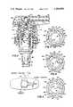
- FIG. 1is a schematic top plan view of a product container employing a pump constructed in accordance with the principles of the present invention, the spout of the pump being illustrated in solid lines with its longitudinal axis aligned with the elongation of the container and being shown in broken lines in an unlocked position;
- FIG. 2is an enlarged, fragmentary view of the pump partially in cross section and partially in elevation revealing details of construction
- FIG. 3is a top plan view of the locking components of the pump showing the same in a locked condition
- FIG. 4is a top plan view of the locking components in an unlocked condition with the locking lugs aligned with their receiving notches;
- FIG. 5is a top plan view of the locking components showing the locking lugs in a random position normally associated with regular pumping operations;
- FIG. 6is a transverse cross-sectional view through the pump taken substantially along line 6--6 of FIG. 2;
- FIG. 7is a cross-sectional view through the locking components of the pump taken substantially along the oblique sight line 7--7 of FIG. 6;
- FIG. 8is a fragmentary elevational view of components of the pump adjacent its upper end, parts being broken away and shown in cross section for clarity;
- FIG. 9is a fragmentary side elevational view of the pump and associated container with the pumping head shown in cross section to reveal partial details of the lock therebeneath.
- the pump 10is installed upon the closure 12 of a container 14 having a threaded neck finish (not shown) which mates with internal threads 16 of the closure 12 formed on the annular sidewall 18 thereof.
- the top wall 20 of the closure 12is provided with a centrally disposed opening 22 through which the upper portion of tubular body 24 of the pump 10 projects.
- An external, annular flange 26 on the body 24rests upon the top edge of the neck finish in order to suspend the lower portion of the body 24 down into the interior of the container 14.
- the pump 10further includes an annular collar 28 snapped onto the upper end of the body 24 via parallel, interfitting beads and grooves denoted broadly by the numeral 30.
- the fit between beads and grooves 30is such that the collar 28 may rotate about the upper end of the body 24 if sufficient torque is applied to the collar 28, it being noted that the collar 28 is not merely loosely held onto the body 24, however.
- the collar 28serves to attach pump 10 to the closure 12 such that the closure 12 and the pump 10 together form an assembly which can be threaded onto and off of the container 14 as desired.
- the collar 28is located in axial registration with the body 24 and functions to provide a bearing surface for the reciprocable plunger 32 of the pump 10 having an operating head 34 at its upper end which may be manually depressed and raised in order to reciprocate the plunger 32 and operate the pump 10.
- a piston seal(not shown) adjacent the lower end of the plunger 32 makes sealing contact with the interior surface of the body 24 for the purpose of pumping products into the body 24 below the seal during an upstroke of the plunger 32, and for pumping such products out of the body 24 via a passage 36 in the plunger 32 during a down stroke of the latter. From the passage 36, the products flow to an outlet 38 in the spout 40 of the head 34.
- the pump 10further includes an inlet 42 at the lower end of the body 24 communicating the interior of the container 14 with the interior of the body 24.
- Inlet 42is controlled by a ball check valve 44 which seats against the inlet 42 to close the latter during a down stroke of the plunger 32 and which rises off the inlet 42 to open the latter during an upstroke of the plunger 32.
- Upward movement of the ball valve 44is limited by a series of inwardly projecting nibs 46 on the body 24 a short distance above the ball 44.
- a second ball valve 48is located within the passage 36 adjacent the upper end of the plunger 32 for controlling an outlet 50 that communicates the interior passage 36 with the outlet 38 of spout 40.
- Upper ball valve 48is yieldably biased into a position closing the outlet 50 by a compression spring 52, the ball 48 closing the outlet 50 during an upstroke of the plunger 32 and opening the outlet 50 during a down stroke of the plunger 32.
- Vent holes 54 in the body 24 slightly below the flange 26allow the ingress of ambient air into the container 14 from along the interface of the plunger 32 and the collar 28 for the purpose of equalizing pressure externally and internally of the container 14 during the upstroke of the plunger 32.
- the plunger 32is provided with a hollow projection 56 depending from the lower end thereof for the purpose of holding down the ball check valve 44 at such time as the plunger 32 is in a fully depressed position as illustrated in FIG. 2. Suitable orifices (not shown) are provided in the projection 56 for the purpose of allowing entry of products into the passage 36 of plunger 32 during the down stroke of the latter.
- the plunger 32is of reduced diameter adjacent its upper end and is securely received within a depending annular portion 58 of the head 34 at that location. Interfitting beads and grooves 60 permit the plunger 32 and the annular portion 58 to be snapped together in tight interengagement so that the head 34 and the plunger 32 effectively become a single unit without relative rotational movement being permitted between such two components.
- a sleeve 62receives the depending annular portion 58 and has a radially inwardly disposed, annular section 63 at its lower end that is trapped between the lower end 64 of the annular head portion 58 and an upwardly facing ledge 66 formed at the initiation of the reduced diameter portion of the plunger 32 so that sleeve 62 effectively forms a part of and is carried with the plunger 32 during reciprocation of the latter.
- an indentation 68 in the top edge of the sleeve 62receives the normally horizontally extending tubular section 70 of the spout 40 containing the internal outlet passage 38.
- a downwardly opening annular groove 72is formed in the bottom of the sleeve 62.
- the collar 28includes an outer cylinder 74, an intermediate cylinder 76 of reduced diameter with respect to the outer cylinder 74, and an inner cylinder 78 of still further reduced diameter.
- the intermediate cylinder 76is recessed from the top of the outer cylinder 74 and is connected thereto by a series of three radially extending bridges 80 as seen in FIG. 3 and FIG. 5, as well as FIG. 2, while the inner cylinder 78 is substantially further recessed and is integrally connected to the intermediate cylinder 76 at its lower end via a continuous, annular connection 82.
- the upper end of the body 24projects securely between the outer cylinder 74 and the intermediate cylinder 76, and the sleeve 62 is received between the intermediate cylinder 76 and the depending annular portion 58 of the head 34.
- the fit between the sleeve 62 and the intermediate cylinder 76is such that the head 34 and the sleeve 62 can rotate relative to the intermediate cylinder 76.
- the fit between the inner cylinder 78 and the plunger 32is such that the latter can rotate freely relative to the cylinder 78, although the annular connection 82 between the intermediate cylinder 76 and the inner cylinder 78 is provided with an upwardly projecting, annular tongue 84 that is sealingly and matingly received within the groove 72 of sleeve 62 when the plunger 32 is in its fully depressed position.
- locking meansbroadly denoted by the numeral 86 is provided between the plunger 32 and the collar 28 for the purpose of releasably retaining the plunger 32 in a down-and-locked position as illustrated in FIG. 2.
- the locking means 86includes a series of three radially projecting lugs 88 on the sleeve 62 of the plunger 32, a corresponding set of three lug-receiving notches 90 in the collar 28, and a corresponding series of three retaining shoulders 92 interspersed between the receiving notches 90.
- the notches 90open axially of the pump 10 so as to be in position to receive the lugs 88 when the latter are properly vertically registered therewith, and the shoulders 92 project radially inwardly beyond the radially outer terminations of the lugs 88. Accordingly, when the lugs 88 are inserted into the notches 90 and the plunger 32 is then rotated in a clockwise direction viewing FIGS. 3, 4 and 5, the lugs 88 come to underlie the shoulders 92 and prevent upward extension of the plunger 32. On the other hand, when the pump is in an unlocked mode as illustrated in FIG. 5, the lugs 88 overlie the shoulders 92 and thereby serve as stroke limiters upon depression of the plunger 32.
- One of the lugs 88ais narrower than the other two lugs 88b and 88c and, correspondingly, one of the notches 90a is narrower than the other two notches 90b and 90c.
- the lugs 88may only be received by the notches 90 when the lug 88a is registered with the notch 90a.
- each of the shoulders 92is provided with a depending abutment 94 located at the clockwise end of the shoulder 92 as viewed from the top.
- Each abutment 94projects radially inwardly to the same extent as its corresponding shoulder 92 so as to be located in the path of travel of the corresponding lug 88a, 88b or 88c as it is shifted beneath the shoulder 92 during clockwise rotation of the plunger 32.
- Abutments 94thereby serve to limit such rotation of the plunger 32 in a clockwise direction when the pump 10 is in its locking mode.
- each shoulder 92is provided with a lug-engaging surface 96 that is progressively inclined axially downwardly as the abutment 94 is approached.
- Such surface 96has the effect of applying progressively increasing, axially downwardly directed compressive loading to the plunger 32 through the lugs 88 as the plunger 32 is rotated into its locked mode with the lugs 88 engaging the abutments 94.
- the general operation of the pump 10is readily apparent from the foregoing description. Suffice it to point out, then, that as the plunger 32 is depressed, a portion or dose of products held within the container 14 is dispensed through the spout 40. As the plunger 32 is withdrawn or extended, the next charge of products is drawn into the body 24 to be dispensed during the following down stroke of the plunger 32.
- the lugs 88 of the lock 86overlie the shoulders 92 during such operation, a typical example of that relationship being illustrated in FIGS. 5 and 9, although because the plunger 32 is freely rotatable within the collar 28 when unlocked, the lugs 88 may be located at any of an infinite number of random locations about the collar 28.
- the lugs 88quite effectively limit the down stroke of the plunger 32 by engaging the top side of the shoulders 92 upon depression of the plunger 32 to thereby help assure that precise quantities of products are dispensed during repeated pumping strokes.
- the plunger 32may be placed in its locking mode only when the plunger 32 is in one particular rotative position, i.e., that position in which the small lug 88a is aligned with its corresponding, small notch 90a.
- the plunger 32may be placed in its locking mode only when the plunger 32 is in one particular rotative position, i.e., that position in which the small lug 88a is aligned with its corresponding, small notch 90a.
- the chances that the small lug 88a will be aligned with its small notch 90a during any given down stroke of the plunger 32are relatively slim. Consequently, during normal use, there is little likelihood that the down strokes of the plunger 32 will exceed the normal down stroke determined by the lugs 88 striking the top sides of the shoulders 92.
- Primary use of the lock 86may thus be seen as occurring during initial shipment of the goods from the factory where the containers 14 are filled with products, and also during such time as the goods are displayed on merchandising shelves and carried home with other groceries and the like.
- shifting the plunger 32 to its fully depressed position with the small lug 88a fully aligned with its small notch 90a as illustrated in FIG. 4, and thereupon rotating the plunger 32 in a clockwise direction viewing that figurecauses the lugs 88 to slip beneath the overhanging shoulders 92 as illustrated in FIG. 3.
- the fact that the collar 28 is indeed rotatable relative to the body 24 upon the application of sufficiently high torquecan be of assistance during preparation of the containers 14 and their pumps 10 for packaging.
- the container 14 with which the pump 10 is associatedmay frequently be generally oval in transverse cross section.
- the pump 10includes a dispensing spout such as the spout 40 herein illustrated, it is desirable for the sake of packaging efficiencies to orient the spout 40 in line with the elongation of the container 14 in the manner illustrated in solid lines in FIG. 1.
- such orientingmust not interfere or adversely affect the locking feature of the pump 10.
- orienting the spout 40 as a final step on the automated "fill line" for the container 14must not unlock the plunger 32 or otherwise adversely affect the lock 86.
- the lugs 88are in their full clockwise most positions engaging the abutments 94.
- the spout 40may be engaged by a stationary cam or the like alongside the fill line to drive the spout 40 in a clockwise direction sufficient to properly align it with the elongation of the container 14. Because the lugs 88 are fully against the abutments 94 at this time, there is no movement of the plunger 32 relative to the collar 28.
Landscapes
- Engineering & Computer Science (AREA)
- Mechanical Engineering (AREA)
- Containers And Packaging Bodies Having A Special Means To Remove Contents (AREA)
- Reciprocating Pumps (AREA)
Abstract
Description
Claims (7)
Priority Applications (3)
| Application Number | Priority Date | Filing Date | Title |
|---|---|---|---|
| US06/207,892US4369899A (en) | 1980-11-18 | 1980-11-18 | Down-locking pump |
| CA000413255ACA1204416A (en) | 1980-11-18 | 1982-10-12 | Down-locking pump |
| AU89324/82AAU556441B2 (en) | 1980-11-18 | 1982-10-13 | Plunger lock for dispenser pump |
Applications Claiming Priority (1)
| Application Number | Priority Date | Filing Date | Title |
|---|---|---|---|
| US06/207,892US4369899A (en) | 1980-11-18 | 1980-11-18 | Down-locking pump |
Publications (1)
| Publication Number | Publication Date |
|---|---|
| US4369899Atrue US4369899A (en) | 1983-01-25 |
Family
ID=22772403
Family Applications (1)
| Application Number | Title | Priority Date | Filing Date |
|---|---|---|---|
| US06/207,892Expired - LifetimeUS4369899A (en) | 1980-11-18 | 1980-11-18 | Down-locking pump |
Country Status (3)
| Country | Link |
|---|---|
| US (1) | US4369899A (en) |
| AU (1) | AU556441B2 (en) |
| CA (1) | CA1204416A (en) |
Cited By (42)
| Publication number | Priority date | Publication date | Assignee | Title |
|---|---|---|---|---|
| US4433799A (en) | 1982-03-31 | 1984-02-28 | Calmar, Inc. | Liquid dispensing pump arrangement with selective stroke restriction |
| US4458832A (en)* | 1981-12-18 | 1984-07-10 | Corsette Douglas Frank | Liquid dispensing pump |
| FR2540833A1 (en)* | 1983-02-16 | 1984-08-17 | Realex Corp | GUARANTEE DEVICE FOR A PUMP DISPENSER PROVIDED ON A LIQUID CONTAINER |
| US4479589A (en)* | 1982-06-07 | 1984-10-30 | Realex Corporation | Plunger lock for manual dispensing pump |
| US4512501A (en)* | 1982-08-23 | 1985-04-23 | Realex Corporatrion | Down-locking dispensing pump with guided check valve hold-down structure |
| FR2555672A1 (en)* | 1983-11-30 | 1985-05-31 | Realex Corp | DISPENSING PUMP EQUIPPED WITH A ROTATION LOCK BETWEEN THE RING AND THE BODY |
| US4524888A (en)* | 1981-07-30 | 1985-06-25 | Canyon Corporation | Dispenser |
| US4871092A (en)* | 1982-07-10 | 1989-10-03 | Ing. Erich Pfeiffer Gmbh & Co. Kg | Atomizing or metering pump |
| US4877158A (en)* | 1985-10-14 | 1989-10-31 | Kohler Tilmann L | Fluid dispensing apparatus |
| US4889262A (en)* | 1988-06-07 | 1989-12-26 | L'oreal, S. A. | Locking system for pump dispenser |
| US4915601A (en)* | 1985-03-14 | 1990-04-10 | Mega Product- Und Verpackungsentwicklung Marketing Gmbh & Co. Kommanditgesellschaft | Dosaging pump with pump bellows on bottles or the like |
| US5335830A (en)* | 1992-10-21 | 1994-08-09 | Bespak Plc | Pump dispenser for lotions and/or large doses of product |
| WO1996003624A1 (en)* | 1994-07-21 | 1996-02-08 | Emson, Inc. | Dispensing pump which is lockable and sealable for transportation and storage |
| US5655688A (en)* | 1994-10-19 | 1997-08-12 | Aptargroup, Inc. | Atomizing pump with high stroke speed enhancement and valve system therefor |
| US5725128A (en)* | 1996-03-08 | 1998-03-10 | Contico International, Inc. | Manually operated reciprocating liquid pump that locks and seals in up and down positions |
| US5850948A (en)* | 1996-09-13 | 1998-12-22 | Valois S.A. | Finger-operable pump with piston biasing post |
| US6206245B1 (en)* | 1998-07-24 | 2001-03-27 | L'oreal | Pump with a delivery valve including a ball |
| FR2808783A1 (en)* | 2000-05-11 | 2001-11-16 | Lir France Sa | Cosmetic dispenser comprises body and head with pump and valve and supply pipe submerged in product and dispensing pipe emerging through orifice to outside |
| US6458280B1 (en) | 1999-01-06 | 2002-10-01 | Emerson Electric Co. | Device and method for dispensing bacteriostat into humidifier |
| US6601735B2 (en) | 2001-01-19 | 2003-08-05 | Valois S.A. | Fluid dispenser device |
| EP1352875A1 (en)* | 2002-04-12 | 2003-10-15 | Saint Gobain-Calmar Inc. | Child-resistant liquid dispenser |
| US6695171B2 (en) | 2002-02-12 | 2004-02-24 | Seaquistperfect Dispensing Foreign, Inc. | Pump dispenser |
| US20060113329A1 (en)* | 2004-11-29 | 2006-06-01 | Seaquisperfect Dispensing Foreign, Inc. | Dispenser with lock |
| US20070080174A1 (en)* | 2005-10-06 | 2007-04-12 | Coe Matthew T | Fluid dispenser with a safety dispensing actuator and fluid dispensing product containing the same |
| US7249692B2 (en) | 2004-11-29 | 2007-07-31 | Seaquistperfect Dispensing Foreign, Inc. | Dispenser with lock |
| US20080251537A1 (en)* | 2007-04-16 | 2008-10-16 | Roy Kuo | Pump dispenser used with lotion bottle |
| US20100219209A1 (en)* | 2006-06-09 | 2010-09-02 | Yaowu Ding | Lotion pump |
| US20100230443A1 (en)* | 2006-06-15 | 2010-09-16 | Yaowu Ding | Lotion pump with an externally installed spring |
| US20110174840A1 (en)* | 2009-11-26 | 2011-07-21 | Brian Robert Law | Dispenser pumps |
| US20130200106A1 (en)* | 2012-02-02 | 2013-08-08 | Hana Co., Ltd | Cosmetic container having release prevention device |
| US20150239643A1 (en)* | 2012-09-11 | 2015-08-27 | Yonwoo Co., Ltd. | Dispenser container comprising safety button structure |
| US9908132B2 (en)* | 2015-04-17 | 2018-03-06 | The Procter & Gamble Company | Mechanism to prevent actuator of a pump dispenser to prematurely open and leak |
| US20180369845A1 (en)* | 2017-06-23 | 2018-12-27 | Albea Services | Pump actuator head |
| US10640270B2 (en) | 2016-09-28 | 2020-05-05 | The Procter And Gamble Plaza | Closure mechanism that prevents accidental initial opening of a container |
| US10759576B2 (en) | 2016-09-28 | 2020-09-01 | The Procter And Gamble Company | Closure interlocking mechanism that prevents accidental initial opening of a container |
| US10836559B2 (en) | 2017-11-23 | 2020-11-17 | The Procter And Gamble Company | Closure for a container comprising three positions |
| US10836560B2 (en) | 2017-11-23 | 2020-11-17 | The Procter And Gamble Company | Closure for a container having an asymmetrical protrusion |
| CN113474087A (en)* | 2019-01-08 | 2021-10-01 | 泰普勒斯特有限责任公司 | Device for dispensing a fluid or a mixture |
| US11141751B1 (en)* | 2019-07-12 | 2021-10-12 | Empire-Emco, Inc. | Child resistant sprayer |
| US11179740B2 (en)* | 2018-07-31 | 2021-11-23 | Aptar Italia S.P.A. | Dispenser for dispensing a fluid |
| JP2022011091A (en)* | 2020-06-29 | 2022-01-17 | 株式会社吉野工業所 | Blowout container |
| CN117508887A (en)* | 2022-12-27 | 2024-02-06 | 天舟医疗(苏州)有限公司 | Impact-resistant pump |
Citations (9)
| Publication number | Priority date | Publication date | Assignee | Title |
|---|---|---|---|---|
| US2083058A (en)* | 1932-10-20 | 1937-06-08 | Leakproof Sprayer Co | Spraying device |
| US2088790A (en)* | 1933-08-23 | 1937-08-03 | Charles K Huthsing | Pump and fire extinguisher |
| US2103932A (en)* | 1933-09-12 | 1937-12-28 | Bernhardt Rudolph | Container and pump |
| US2846124A (en)* | 1956-10-08 | 1958-08-05 | Drackett Co | Dispensing pump unit |
| US3086716A (en)* | 1961-12-15 | 1963-04-23 | Coty Inc | Atomizers |
| US3321111A (en)* | 1965-12-28 | 1967-05-23 | Merck & Co Inc | Pistol grip pump-type dispenser |
| US3422996A (en)* | 1966-11-25 | 1969-01-21 | Valve Corp Of America | Safety actuator cap for hand-held dispensers |
| US3706401A (en)* | 1970-07-15 | 1972-12-19 | Sunbeam Plastics Corp | Child-proof overcap for an aerosol can |
| US4162746A (en)* | 1977-06-22 | 1979-07-31 | Diamond International Corporation | Liquid dispenser locking means |
- 1980
- 1980-11-18USUS06/207,892patent/US4369899A/ennot_activeExpired - Lifetime
- 1982
- 1982-10-12CACA000413255Apatent/CA1204416A/ennot_activeExpired
- 1982-10-13AUAU89324/82Apatent/AU556441B2/ennot_activeCeased
Patent Citations (9)
| Publication number | Priority date | Publication date | Assignee | Title |
|---|---|---|---|---|
| US2083058A (en)* | 1932-10-20 | 1937-06-08 | Leakproof Sprayer Co | Spraying device |
| US2088790A (en)* | 1933-08-23 | 1937-08-03 | Charles K Huthsing | Pump and fire extinguisher |
| US2103932A (en)* | 1933-09-12 | 1937-12-28 | Bernhardt Rudolph | Container and pump |
| US2846124A (en)* | 1956-10-08 | 1958-08-05 | Drackett Co | Dispensing pump unit |
| US3086716A (en)* | 1961-12-15 | 1963-04-23 | Coty Inc | Atomizers |
| US3321111A (en)* | 1965-12-28 | 1967-05-23 | Merck & Co Inc | Pistol grip pump-type dispenser |
| US3422996A (en)* | 1966-11-25 | 1969-01-21 | Valve Corp Of America | Safety actuator cap for hand-held dispensers |
| US3706401A (en)* | 1970-07-15 | 1972-12-19 | Sunbeam Plastics Corp | Child-proof overcap for an aerosol can |
| US4162746A (en)* | 1977-06-22 | 1979-07-31 | Diamond International Corporation | Liquid dispenser locking means |
Cited By (56)
| Publication number | Priority date | Publication date | Assignee | Title |
|---|---|---|---|---|
| US4524888A (en)* | 1981-07-30 | 1985-06-25 | Canyon Corporation | Dispenser |
| US4458832A (en)* | 1981-12-18 | 1984-07-10 | Corsette Douglas Frank | Liquid dispensing pump |
| US4433799A (en) | 1982-03-31 | 1984-02-28 | Calmar, Inc. | Liquid dispensing pump arrangement with selective stroke restriction |
| US4479589A (en)* | 1982-06-07 | 1984-10-30 | Realex Corporation | Plunger lock for manual dispensing pump |
| US4871092A (en)* | 1982-07-10 | 1989-10-03 | Ing. Erich Pfeiffer Gmbh & Co. Kg | Atomizing or metering pump |
| US4512501A (en)* | 1982-08-23 | 1985-04-23 | Realex Corporatrion | Down-locking dispensing pump with guided check valve hold-down structure |
| FR2540833A1 (en)* | 1983-02-16 | 1984-08-17 | Realex Corp | GUARANTEE DEVICE FOR A PUMP DISPENSER PROVIDED ON A LIQUID CONTAINER |
| US4538748A (en)* | 1983-02-16 | 1985-09-03 | Realex Corporation | Tamper deterring unlocking restricter for down locking pump dispensers |
| FR2555672A1 (en)* | 1983-11-30 | 1985-05-31 | Realex Corp | DISPENSING PUMP EQUIPPED WITH A ROTATION LOCK BETWEEN THE RING AND THE BODY |
| DE3440214A1 (en)* | 1983-11-30 | 1985-06-05 | Realex Corp., Kansas City, Mo. | DISPENSING PUMP |
| US4589574A (en)* | 1983-11-30 | 1986-05-20 | Realex Corporation | Dispensing pump having collar-to-body anti-rotation interlock |
| AU567976B2 (en)* | 1983-11-30 | 1987-12-10 | Realex Corp. | Dispensing pump collar-to-body anti-rotation interlock |
| US4915601A (en)* | 1985-03-14 | 1990-04-10 | Mega Product- Und Verpackungsentwicklung Marketing Gmbh & Co. Kommanditgesellschaft | Dosaging pump with pump bellows on bottles or the like |
| US4877158A (en)* | 1985-10-14 | 1989-10-31 | Kohler Tilmann L | Fluid dispensing apparatus |
| US4889262A (en)* | 1988-06-07 | 1989-12-26 | L'oreal, S. A. | Locking system for pump dispenser |
| US5335830A (en)* | 1992-10-21 | 1994-08-09 | Bespak Plc | Pump dispenser for lotions and/or large doses of product |
| WO1996003624A1 (en)* | 1994-07-21 | 1996-02-08 | Emson, Inc. | Dispensing pump which is lockable and sealable for transportation and storage |
| US5524793A (en)* | 1994-07-21 | 1996-06-11 | Emson, Inc. | Dispensing pump which is lockable and sealable for transporation and storage |
| US5655688A (en)* | 1994-10-19 | 1997-08-12 | Aptargroup, Inc. | Atomizing pump with high stroke speed enhancement and valve system therefor |
| US5725128A (en)* | 1996-03-08 | 1998-03-10 | Contico International, Inc. | Manually operated reciprocating liquid pump that locks and seals in up and down positions |
| US5850948A (en)* | 1996-09-13 | 1998-12-22 | Valois S.A. | Finger-operable pump with piston biasing post |
| US6206245B1 (en)* | 1998-07-24 | 2001-03-27 | L'oreal | Pump with a delivery valve including a ball |
| US6458280B1 (en) | 1999-01-06 | 2002-10-01 | Emerson Electric Co. | Device and method for dispensing bacteriostat into humidifier |
| FR2808783A1 (en)* | 2000-05-11 | 2001-11-16 | Lir France Sa | Cosmetic dispenser comprises body and head with pump and valve and supply pipe submerged in product and dispensing pipe emerging through orifice to outside |
| US6601735B2 (en) | 2001-01-19 | 2003-08-05 | Valois S.A. | Fluid dispenser device |
| US6695171B2 (en) | 2002-02-12 | 2004-02-24 | Seaquistperfect Dispensing Foreign, Inc. | Pump dispenser |
| EP1352875A1 (en)* | 2002-04-12 | 2003-10-15 | Saint Gobain-Calmar Inc. | Child-resistant liquid dispenser |
| AU2003203456B2 (en)* | 2002-04-12 | 2007-01-18 | Saint-Gobain Calmar Inc. | Child-resistant liquid dispenser |
| US20060113329A1 (en)* | 2004-11-29 | 2006-06-01 | Seaquisperfect Dispensing Foreign, Inc. | Dispenser with lock |
| US7249692B2 (en) | 2004-11-29 | 2007-07-31 | Seaquistperfect Dispensing Foreign, Inc. | Dispenser with lock |
| US20070080174A1 (en)* | 2005-10-06 | 2007-04-12 | Coe Matthew T | Fluid dispenser with a safety dispensing actuator and fluid dispensing product containing the same |
| US20100219209A1 (en)* | 2006-06-09 | 2010-09-02 | Yaowu Ding | Lotion pump |
| US8573448B2 (en)* | 2006-06-09 | 2013-11-05 | Yaowu Ding | Lotion pump |
| US20100230443A1 (en)* | 2006-06-15 | 2010-09-16 | Yaowu Ding | Lotion pump with an externally installed spring |
| US20080251537A1 (en)* | 2007-04-16 | 2008-10-16 | Roy Kuo | Pump dispenser used with lotion bottle |
| US7931172B2 (en)* | 2007-04-16 | 2011-04-26 | Roy Kuo | Pump dispenser used with lotion bottle |
| US20110174840A1 (en)* | 2009-11-26 | 2011-07-21 | Brian Robert Law | Dispenser pumps |
| US8827121B2 (en)* | 2009-11-26 | 2014-09-09 | Rieke Corporation | Dispenser pumps |
| US20130200106A1 (en)* | 2012-02-02 | 2013-08-08 | Hana Co., Ltd | Cosmetic container having release prevention device |
| US8863988B2 (en)* | 2012-02-02 | 2014-10-21 | Hana Co., Ltd. | Cosmetic container having release prevention device |
| US9745117B2 (en)* | 2012-09-11 | 2017-08-29 | Yonwoo Co., Ltd. | Dispenser container comprising safety button structure |
| US20150239643A1 (en)* | 2012-09-11 | 2015-08-27 | Yonwoo Co., Ltd. | Dispenser container comprising safety button structure |
| US9908132B2 (en)* | 2015-04-17 | 2018-03-06 | The Procter & Gamble Company | Mechanism to prevent actuator of a pump dispenser to prematurely open and leak |
| US10640270B2 (en) | 2016-09-28 | 2020-05-05 | The Procter And Gamble Plaza | Closure mechanism that prevents accidental initial opening of a container |
| US10759576B2 (en) | 2016-09-28 | 2020-09-01 | The Procter And Gamble Company | Closure interlocking mechanism that prevents accidental initial opening of a container |
| US20180369845A1 (en)* | 2017-06-23 | 2018-12-27 | Albea Services | Pump actuator head |
| US10384222B2 (en)* | 2017-06-23 | 2019-08-20 | Albea Services | Pump actuator head |
| US10836559B2 (en) | 2017-11-23 | 2020-11-17 | The Procter And Gamble Company | Closure for a container comprising three positions |
| US10836560B2 (en) | 2017-11-23 | 2020-11-17 | The Procter And Gamble Company | Closure for a container having an asymmetrical protrusion |
| US11179740B2 (en)* | 2018-07-31 | 2021-11-23 | Aptar Italia S.P.A. | Dispenser for dispensing a fluid |
| CN113474087A (en)* | 2019-01-08 | 2021-10-01 | 泰普勒斯特有限责任公司 | Device for dispensing a fluid or a mixture |
| US11648576B2 (en) | 2019-01-08 | 2023-05-16 | Taplast S.R.L. | Device for dispensing fluids or mixtures |
| CN113474087B (en)* | 2019-01-08 | 2023-07-14 | 泰普勒斯特有限责任公司 | Devices for dispensing fluids or mixtures |
| US11141751B1 (en)* | 2019-07-12 | 2021-10-12 | Empire-Emco, Inc. | Child resistant sprayer |
| JP2022011091A (en)* | 2020-06-29 | 2022-01-17 | 株式会社吉野工業所 | Blowout container |
| CN117508887A (en)* | 2022-12-27 | 2024-02-06 | 天舟医疗(苏州)有限公司 | Impact-resistant pump |
Also Published As
| Publication number | Publication date |
|---|---|
| CA1204416A (en) | 1986-05-13 |
| AU8932482A (en) | 1984-04-19 |
| AU556441B2 (en) | 1986-11-06 |
Similar Documents
| Publication | Publication Date | Title |
|---|---|---|
| US4369899A (en) | Down-locking pump | |
| US4496082A (en) | Liquid dispensing pump | |
| US4889262A (en) | Locking system for pump dispenser | |
| US4286736A (en) | Liquid Dispenser | |
| US4479589A (en) | Plunger lock for manual dispensing pump | |
| US3062416A (en) | Liquid dispenser | |
| US4410107A (en) | Liquid dispensing pump | |
| US4538748A (en) | Tamper deterring unlocking restricter for down locking pump dispensers | |
| US4512501A (en) | Down-locking dispensing pump with guided check valve hold-down structure | |
| JPH08247038A (en) | Pump distribution device | |
| US4375266A (en) | Down-locking dispensing pump with side-orificed, product-mixing ball hold-down | |
| JPS6069269A (en) | Pressure accumulating type distribution pump | |
| US10166563B2 (en) | Pump systems, pump engines, and methods of making the same | |
| US8499985B2 (en) | Automatic dispensing cap for squeezable bottle | |
| US6202717B1 (en) | Dispensing bottle closure | |
| US20140151404A1 (en) | Automatic dispensing cap for a squeezeable bottle | |
| US3029742A (en) | Dispensing pump for fluids | |
| JP3059400B2 (en) | Push type dispenser | |
| US5878916A (en) | Metered dosage undirectional tracked pumped dispenser | |
| US3444906A (en) | Apparatus for filling aerosol cans | |
| US2117296A (en) | Dispensing package for liquids | |
| NZ202197A (en) | Pump plunger locked down against seal by radial lugs | |
| JP2577913Y2 (en) | dispenser | |
| US3268122A (en) | Pump with dual, fluid pressure actuated pistons and movable pick-up tube | |
| GB2062121A (en) | Lockable pumping device |
Legal Events
| Date | Code | Title | Description |
|---|---|---|---|
| STCF | Information on status: patent grant | Free format text:PATENTED CASE | |
| AS | Assignment | Owner name:CALMAR INC., 40 STIRLING ROAD, WATCHUNG, NJ 07060, Free format text:ASSIGNMENT OF ASSIGNORS INTEREST.;ASSIGNOR:REALEX CORPORATION;REEL/FRAME:004983/0866 Effective date:19881128 Owner name:CALMAR INC., A CORP. OF DE, NEW JERSEY Free format text:ASSIGNMENT OF ASSIGNORS INTEREST;ASSIGNOR:REALEX CORPORATION;REEL/FRAME:004983/0866 Effective date:19881128 | |
| AS | Assignment | Owner name:CALMAR INC., A DE CORP., NEW JERSEY Free format text:ASSIGNMENT OF ASSIGNORS INTEREST.;ASSIGNOR:REALEX CORPORATION;REEL/FRAME:005020/0968 Effective date:19881130 Owner name:CITICORP NORTH AMERICA, INC., AS AGENT, CALIFORNIA Free format text:SECURITY INTEREST;ASSIGNOR:CALMAR INC.;REEL/FRAME:005020/0974 Effective date:19881208 | |
| AS | Assignment | Owner name:UNITED STATES TRUST COMPANY OF NEW YORK, NEW YORK Free format text:SECURITY INTEREST;ASSIGNOR:CALMAR INC.;REEL/FRAME:006608/0452 Effective date:19911223 | |
| AS | Assignment | Owner name:CALMAR INC., A CORPORATION OF DELAWARE, CALIFORNIA Free format text:RELEASE BY SECURED PARTY OF A SECURITY AGREEMENT RECORDED AT REEL 5020 FRAME 0974 AND DATED 12-08-88;ASSIGNOR:CITICORP NORTH AMERICA, INC.;REEL/FRAME:006082/0535 Effective date:19911212 | |
| AS | Assignment | Owner name:CALMAR INC., A DE CORP., CALIFORNIA Free format text:TERMINATION AND RELEASE OF INTELLECTUAL PROPERTY PLEDGE AGREEMENT;ASSIGNOR:UNITED STATES TRUST COMPANY OF NEW YORK, AS COLLATERAL AGENT;REEL/FRAME:007648/0338 Effective date:19950918 Owner name:MELLON BANK, N.A., AS COLLATERAL AGENT, PENNSYLVAN Free format text:PATENT COLLATERAL SECURITY AGREEMENT;ASSIGNOR:CALMAR INC., A DELAWARE CORPORATION;REEL/FRAME:007662/0551 Effective date:19950918 | |
| AS | Assignment | Owner name:BANQUE INDOSUEZ, AS COLLATERAL AGENT, NEW YORK Free format text:SECURITY INTEREST;ASSIGNOR:MELLON BANK, N.A., AS COLLATERAL AGENT;REEL/FRAME:008186/0912 Effective date:19961025 | |
| AS | Assignment | Owner name:CALMAR, INC., CALIFORNIA Free format text:TERMINATION OF PATENT SECURITY INTERESTS;ASSIGNOR:BANQUE INDOSUEZ, AS COLLATERAL AGENT;REEL/FRAME:009375/0018 Effective date:19980722 |