US4365639A - Catheter, cardiac pacemaker and method of pacing - Google Patents
Catheter, cardiac pacemaker and method of pacingDownload PDFInfo
- Publication number
- US4365639A US4365639AUS06/242,705US24270581AUS4365639AUS 4365639 AUS4365639 AUS 4365639AUS 24270581 AUS24270581 AUS 24270581AUS 4365639 AUS4365639 AUS 4365639A
- Authority
- US
- United States
- Prior art keywords
- catheter
- heart
- sensing
- electrodes
- wave
- Prior art date
- Legal status (The legal status is an assumption and is not a legal conclusion. Google has not performed a legal analysis and makes no representation as to the accuracy of the status listed.)
- Expired - Lifetime
Links
- 230000000747cardiac effectEffects0.000titleclaimsabstractdescription47
- 238000000034methodMethods0.000titleclaimsabstractdescription32
- 210000002216heartAnatomy0.000claimsabstractdescription74
- 230000004936stimulating effectEffects0.000claimsabstractdescription64
- 210000005245right atriumAnatomy0.000claimsabstractdescription12
- 210000005241right ventricleAnatomy0.000claimsabstractdescription10
- 230000002792vascularEffects0.000claimsabstractdescription7
- 238000003780insertionMethods0.000claimsabstractdescription6
- 230000037431insertionEffects0.000claimsabstractdescription6
- 230000000638stimulationEffects0.000claimsdescription40
- 210000002837heart atriumAnatomy0.000claimsdescription32
- 102100026827Protein associated with UVRAG as autophagy enhancerHuman genes0.000claimsdescription29
- 101710102978Protein associated with UVRAG as autophagy enhancerProteins0.000claimsdescription29
- 230000008569processEffects0.000claimsdescription29
- 230000006870functionEffects0.000claimsdescription28
- 238000000718qrs complexMethods0.000claimsdescription28
- 230000009471actionEffects0.000claimsdescription20
- 230000004044responseEffects0.000claimsdescription16
- 239000004020conductorSubstances0.000claimsdescription11
- 210000003748coronary sinusAnatomy0.000claimsdescription5
- 210000005247right atrial appendageAnatomy0.000claimsdescription4
- 230000002401inhibitory effectEffects0.000claimsdescription3
- 238000012935AveragingMethods0.000claimsdescription2
- 230000006872improvementEffects0.000claims3
- 230000004217heart functionEffects0.000claims2
- 210000001308heart ventricleAnatomy0.000claims2
- 230000001746atrial effectEffects0.000abstractdescription31
- 230000002861ventricularEffects0.000abstractdescription27
- 230000005284excitationEffects0.000abstract1
- 230000008901benefitEffects0.000description6
- 238000010586diagramMethods0.000description6
- 238000001356surgical procedureMethods0.000description6
- 210000003462veinAnatomy0.000description6
- 206010040639Sick sinus syndromeDiseases0.000description4
- 238000013461designMethods0.000description4
- 230000000694effectsEffects0.000description4
- 230000033764rhythmic processEffects0.000description4
- 230000001360synchronised effectEffects0.000description4
- 238000001514detection methodMethods0.000description3
- 230000004213regulation of atrial cardiomyocyte membrane depolarizationEffects0.000description3
- 210000001013sinoatrial nodeAnatomy0.000description3
- 208000009729Ventricular Premature ComplexesDiseases0.000description2
- 238000013459approachMethods0.000description2
- 206010003119arrhythmiaDiseases0.000description2
- 230000006793arrhythmiaEffects0.000description2
- 230000007423decreaseEffects0.000description2
- 238000005516engineering processMethods0.000description2
- 230000000763evoking effectEffects0.000description2
- 238000007667floatingMethods0.000description2
- 230000033001locomotionEffects0.000description2
- 238000005259measurementMethods0.000description2
- 238000012986modificationMethods0.000description2
- 230000004048modificationEffects0.000description2
- 210000003205muscleAnatomy0.000description2
- 210000004165myocardiumAnatomy0.000description2
- 230000034225regulation of ventricular cardiomyocyte membrane depolarizationEffects0.000description2
- 210000000779thoracic wallAnatomy0.000description2
- 206010014664Endocardial fibrosisDiseases0.000description1
- 206010015856ExtrasystolesDiseases0.000description1
- 206010016654FibrosisDiseases0.000description1
- 208000000418Premature Cardiac ComplexesDiseases0.000description1
- 208000001871TachycardiaDiseases0.000description1
- 241001385887TachysSpecies0.000description1
- 206010044565TremorDiseases0.000description1
- 206010047289Ventricular extrasystolesDiseases0.000description1
- 230000002159abnormal effectEffects0.000description1
- 206010003668atrial tachycardiaDiseases0.000description1
- 238000010009beatingMethods0.000description1
- 230000000903blocking effectEffects0.000description1
- 210000005242cardiac chamberAnatomy0.000description1
- 206010061592cardiac fibrillationDiseases0.000description1
- 210000000038chestAnatomy0.000description1
- 238000010276constructionMethods0.000description1
- 230000008602contractionEffects0.000description1
- 230000001627detrimental effectEffects0.000description1
- 238000011161developmentMethods0.000description1
- 230000018109developmental processEffects0.000description1
- 230000003292diminished effectEffects0.000description1
- 238000004070electrodepositionMethods0.000description1
- 230000002600fibrillogenic effectEffects0.000description1
- 230000004761fibrosisEffects0.000description1
- 208000019622heart diseaseDiseases0.000description1
- 210000005003heart tissueAnatomy0.000description1
- 210000003709heart valveAnatomy0.000description1
- 238000009434installationMethods0.000description1
- 230000007257malfunctionEffects0.000description1
- 230000028161membrane depolarizationEffects0.000description1
- 230000037081physical activityEffects0.000description1
- 230000010287polarizationEffects0.000description1
- 230000002028prematureEffects0.000description1
- 230000000750progressive effectEffects0.000description1
- 230000002685pulmonary effectEffects0.000description1
- 230000036279refractory periodEffects0.000description1
- 230000013577regulation of ventricular cardiomyocyte membrane repolarizationEffects0.000description1
- 230000029058respiratory gaseous exchangeEffects0.000description1
- 230000021670response to stimulusEffects0.000description1
- 230000008054signal transmissionEffects0.000description1
- 230000006794tachycardiaEffects0.000description1
- 230000001225therapeutic effectEffects0.000description1
- 210000001519tissueAnatomy0.000description1
- 206010047302ventricular tachycardiaDiseases0.000description1
Images


Classifications
- A—HUMAN NECESSITIES
- A61—MEDICAL OR VETERINARY SCIENCE; HYGIENE
- A61N—ELECTROTHERAPY; MAGNETOTHERAPY; RADIATION THERAPY; ULTRASOUND THERAPY
- A61N1/00—Electrotherapy; Circuits therefor
- A61N1/18—Applying electric currents by contact electrodes
- A61N1/32—Applying electric currents by contact electrodes alternating or intermittent currents
- A61N1/36—Applying electric currents by contact electrodes alternating or intermittent currents for stimulation
- A61N1/362—Heart stimulators
- A61N1/365—Heart stimulators controlled by a physiological parameter, e.g. heart potential
- A61N1/368—Heart stimulators controlled by a physiological parameter, e.g. heart potential comprising more than one electrode co-operating with different heart regions
- A—HUMAN NECESSITIES
- A61—MEDICAL OR VETERINARY SCIENCE; HYGIENE
- A61N—ELECTROTHERAPY; MAGNETOTHERAPY; RADIATION THERAPY; ULTRASOUND THERAPY
- A61N1/00—Electrotherapy; Circuits therefor
- A61N1/02—Details
- A61N1/04—Electrodes
- A61N1/05—Electrodes for implantation or insertion into the body, e.g. heart electrode
- A61N1/056—Transvascular endocardial electrode systems
Definitions
- This inventionrelates to cardiac pacemakers and in particular, to a new and improved electrode system for a pacemaker.
- Cardiac pacemakersare widely used for stimulating the heart and controlling its rate.
- the hearthas an internal electrical system. Electrical signals produced by the sino-atrial (SA) node control the heart beat under normal circumstances. These signals conduct from the SA node to the right atrium, and are transmitted through the heart to the right ventricle which responds to the transmitted signal producing contraction of the heart. Malfunction in the conduction system between atrium and ventricle sometimes results in failure of signal transmission. Cardiac pacemakers supply this missing signal to the ventricle and result in its beating at a fixed rate.
- SAsino-atrial
- the electrical pulsesare provided at a predetermined rate.
- the electrodewas sewn into the right ventricle requiring open heart surgery. Through later developments, the electrode was mounted in a catheter which was inserted through a vein permitting positioning of the electrode at the apex of the right ventricle, and thus eliminating the requirement for open heart surgery.
- the atriumis depolarized at physiologic body rate determined by signals from the SA node, while the ventricle operates at the predetermined rate controlled by the pacemaker. This is not a wholly satisfactory condition, particularly for active people who require a heart rate varying over a wide range, or for people with severely limiting heart disease.
- two catheterswere utilized, with one catheter positioned within the ventricle and one within the atrium.
- the stimulating electrodes of the two cathetersare operated at a fixed rate but with a time lag between the stimulating pulses.
- This systemsometimes referred to as sequential pacing, is not widely used and can augment cardiac output by only 5-15%.
- the P-wave generated at the atriumis sensed by an electrode sewn into the atrium at the time of open heart surgery.
- the signal from the sensing electrodeis connected to the pulse generator and controls the timing of the stimulating pulse applied to the electrode of the catheter positioned in the ventricle.
- U.S. Pat. No. 3,865,118discloses a system for sequential pacing. Two stimulating electrodes are provided in the atrium and two in the ventricle. Stimulating pulses are sent in sequence to the atrium and to the ventricle. An alternative form of synchronized pacing possibly useful on a short-term basis is discussed at column 7 lines 10-20.
- the patentstates that the atrial electrode could act as a sensor of the patient's T waves, apparently as well as acting as a stimulating electrode, since the preceding sentence refers to atrial stimulating being an advantage.
- the patentindicates that more or less than two electrodes could be used, but no details of construction or use are given.
- U.S. Pat. No. 4,154,247discloses a catheter having two stimulating electrodes for improved stimulation.
- one stimulating electrodeis at the distal tip and the other is a ring spaced from the tip.
- the catheteris formed so that the ring makes direct contact with the tissue of the heart.
- the catheteris branched with a stimulating ring electrode in each branch so that both electrodes can make contact.
- a particular object of the inventionis to provide a new and improved sensing electrode arrangement which produces one or more usable P-wave signals, or in one embodiment QRS signals, for stimulation and timing.
- the electrode system of the present inventionutilizes a single catheter for insertion into the heart through the vascular system, with the electronics for the cardiac pacemaker being mounted subcutaneously on the anterior chest wall and connected to the electrodes by conductors in the catheter.
- stimulating electrode meanstypically a single electrode
- the catheterenters the heart through the cephalic vein and passes through heart valves to the right ventricle.
- Sensing electrode meanstypically one or two pairs of opposed circumferentially mounted electrodes, are carried on the catheter and spaced proximally from the stimulating electrode means, for positioning adjacent to the wall of the atrium.
- the catheteris in the form of a single nondiverging filament.
- the sensing electrodespreferably are connected in pairs for producing bipolar signals, with each signal varying as a function of the cardiac P wave. It has been found that the cardiac P wave can be sensed by electrode means of this circumferential design positioned adjacent to the atrial wall; it is not required that a sensing electrode be embedded in the muscle.
- Differential amplifier circuitryprovides for sensing P wave voltages and discriminating against QRS complexes, which because of the sensing electrode configuration are of miniscule amplitude when compared to sensed P waves, and combining orthogonal P wave voltages to obtain an extremely high level P wave signal.
- An important feature of the inventionis the unique catheter configuration of separate sensing and stimulation electrodes, all in a single filament, with the sensing electrodes close to each other and equidistant from the catheter tip, and with the sensing electrode portion of the catheter free floating in the heart, which provides for bipolar sensing of heart action separate from stimulation, and discrimination against stimulation pulses and undesired heart action signals.
- the locations of the stimulation electrode and the sensing electrodesare varied to provide VVI pacing with QRS sensing and AAI operation for intermittent sinus node dysfunction.
- FIG. 1is a diagrammatic illustration of a portion of a human body illustrating the installation of the cardiac pacer of the present invention
- FIG. 2is an enlarged sectional view of the catheter of FIG. 1 showing the electrode system
- FIG. 3is a sectional view taken along the line 3--3 of FIG. 2;
- FIG. 4is an electrical block diagram illustrating a preferred configuration for the electronics of the pacer
- FIG. 6is a copy of an electrogram illustrating P wave signals achieved by the sensing electrode means of the present invention.
- FIGS. 7-9are diagrams illustrating the operation of the system of the invention.
- FIGS. 10 and 11are sectional views similar to that of FIG. 3, showing alternative embodiments of electrode positions
- FIG. 12is an enlarged view of a heart illustrating the presently preferred positioning of the catheter of the invention.
- FIGS. 13, 14 and 15are views similar to that of FIG. 12 showing alternative positionings of the catheter;
- FIGS. 16-22are copies of electrograms similar to that of FIG. 6 illustrating various heart signals
- FIG. 23is an electrical block diagram illustrating circuitry for VVI and AAI pacing.
- FIGS. 24 and 25are electrical block diagrams similar to that of FIGS. 4 and 5 showing additional circuit details of alternative embodiments.
- FIG. 1illustrates a cardiac pacemaker as installed in a human body.
- An electronics package 10is inserted under the skin at the upper right of the chest and a catheter 11 is inserted in the cephalic vein 12.
- the catheteris secured to the vein in the conventional manner for maintaining the catheter in the inserted position.
- the distal end 15 of the catheteris inserted into the heart through the right atrium 16 to the apex of the right ventricle 17. This is the conventional location for the distal end of the catheter of a cardiac pacer.
- the catheteris in the form of a single nondiverging filament.
- a stimulating electrode 20is mounted at the distal end of the catheter 11 and is connected to the electronics package 10 by a conductor E5 within the catheter.
- a variety of electrode configurationshave been utilized for the stimulating electrode and any of those are suitable for the present invention.
- a unipolar systemis illustrated in FIG. 2 utilizing a single stimulating electrode 10.
- a bipolar systemcould be used, with two spaced electrodes at the distal end of the catheter.
- Atrial sensing electrodesare carried in the catheter spaced a short distance (typically 10-16 cm) from the stimulating electrode 20. In the embodiment illustrated, four electrodes 21, 22, 23, 24 are provided.
- the sensing electrodesare spaced from the distal end of the catheter a distance so that when the catheter is inserted with the distal end in the apex of the ventricle, the sensing electrodes are positioned adjacent the wall of the right atrium, preferably adjacent the high lateral wall, as shown in FIG. 1.
- the essentially linear nature of the cathetertends to prevent the electrodes from making direct contact with the heart tissue.
- the sensing electrodes 21-24are connected to the electronics package 10 by conductors E1-E4, respectively, in the catheter.
- the sensing electrodessense the cardiac P wave in the atrium and produce signals representative of the P wave.
- at least one pair of electrodesis utilized to provide a bipolar signal.
- electrodes 21, 23are connected as inputs to a differential amplifier 27 and electrodes 22, 24 are connected as inputs to another differential amplifier 28.
- the electrode set 21, 23provides a bipolar signal which varies as a function of a component of the P wave.
- the electrode set 22, 24provides another bipolar signal which varies as a function of another component of the P wave, orthogonal to the first component.
- the outputs of the differential amplifiers 27, 28are connected as inputs to a logic unit 29 which functions to select the larger of the amplifier output signals to use as an input to a pulse generating unit 30.
- the pulse generating unit 30may be conventional in design and provides the stimulating pulse on conductor E5, with the other output connected to the body adjacent the electronics package to serve as the circuit ground.
- the amplifiers 27, 28, the logic unit 29 and the pulse generating unit 30are contained in the electronics package 10.
- the logic unit 29could include a voltmeter circuit connected to each incoming differentially amplified atrial signal.
- the logic unitwould consider a P wave to have been accurately detected if either incoming signal has a voltage>1 mv. Although the 0.7 mv. signal is marginal and might be considered possible "false" sensing of a P wave, the 4.3 mv. signal would meet the logical criteria indicating detection of a P wave and this information would then be fed to a pulse generator of standard P synchronous design. The logic unit would select the larger of the two signals if both exceeded the 1 mv. limit.
- the logic unit 29includes voltmeter and analog to digital converters 70, 71, a summer 72, and a level detector 73.
- Each peak to peak analog atrial signalis electronically measured and assigned a digital (numerical) value without sign in converters 70, 71.
- the detector 73is programmed to "detect" a P wave if the combined voltage then exceeds 2 mv.
- Logic circuitry as described aboveis well known in the art.
- This electrode configurationprovides for delivering the stimulating pulse to the desired location in the ventricle and also provides for sensing the P wave in the atrium to provide control for the pulse generating unit, without requiring open heart surgery or electrode insertion in a muscle, and requiring only a single catheter.
- the sensing electrode configurationis maintained in position adjacent the atrium wall, providing a stable orientation and a relatively strong signal from the atrium. At the same time, good rejection of the R wave is achieved. While two sets of sensing electrodes for producing two bipolar signals are illustrated, the system may be operated with one set of electrodes for providing one bipolar signal.
- three electrodesmay be used to provide two bipolar signals, with one electrode common to both signals.
- the use of three electrodesis illustrated in FIGS. 10 and 11, with the electrodes spaced at 90° in FIG. 10 and at 120° in FIG. 11.
- electrodes 21 and 22may form a first pair to provide a bipolar signal on conductors E1 and E3, and electrodes 23 and 22 may form a second pair to provide a bipolar signal on conductors E2 and E4, with E3 and E4 connected together, either within the catheter or outside as desired. Similar electrode connections may be made in FIG. 11.
- the cathetertypically is in the order of two to four millimeters in diameter and in the order of 60 centimeters in length between the electronics package and the distal end.
- the sensing electrodestypically are in the order of 10 to 18 centimeters from the distal end, this spacing being determined by the size of the heart.
- the electrodesare radially spaced from each other about the periphery of the catheter at the same distance from the distal end. This configuration permits sensing a strong P wave, with little interference.
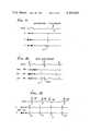
- FIGS. 6 and 16Two electrograms taken on the same patient, one after the other, are shown in FIGS. 6 and 16.
- the upper traceis a conventional ECG indicating the voltage measured at the skin.
- the high frequency signal at the left in the three lower traces of each electrogramis a calibration signal with an amplitude of 1 millivolt.
- the electrogram of FIG. 16was made utilizing a catheter with three pairs of ring electrodes of the type shown in the aforesaid U.S. Pat. No. 3,903,897. One pair was located in the high right atrium, one pair in the mid-right atrium, and one pair in the low right atrium.
- the ECG traceshows a typical heart action as measured by the voltage at the skin of the patient.
- the P waveprecedes the QRS complex with the amplitude of the P wave approximately the same as the amplitude of the QRS complex.
- the electrogram of FIG. 6was produced by substituting the catheter of the present invention for the ring electrode catheter in the measuring system.
- This catheterutilized three electrodes, corresponding to electrodes 21, 22 and 23 of FIG. 3.
- the x traceis the signal measured between electrodes 21 and 22,
- the y traceis the signal measured between electrodes 22 and 23, and
- the x 1 traceis the signal measured between electrodes 21 and 23.
- the P wave signalshows clearly on each on the three traces. However, there is no signal at the time of QRS complex, indicating that the new electrode configuration sharply discriminates against the QRS complex when operating in the atrium.
- FIG. 17is an electrogram similar to that of FIG. 6, with normal QRS signals at 25 and a QRS signal due to premature ventricular contraction (PVC) at 26.
- PVCpremature ventricular contraction
- the x and y P wave signalsare substantial, while there is little or no QRS signal picked up by the orthogonal electrodes in the atrium. This is because the two to four sensing poles of this catheter are so equally distant from the ventricular myocardium that the differential amplifier used to process the signals sees no difference between the ventricular depolarization seen at electrodes 21, 22, 23 or 24. Hence, virtually no signal is recorded at all. Even unipolar ventricular pacing and pacing spikes are discriminated against with this electrode catheter sensing configuration.
- FIGS. 18 and 19are electrograms obtained in the same manner as that of FIG. 6.
- the heartwas being paced independent of the signals received by the sensing portion of the catheter.
- the unipolar pacingone stimulating electrode was positioned in the ventricle and the other beneath the skin; in the bipolar pacing, both stimulating electrodes were positioned in the ventricle.
- the pacing pulses or stimulusare shown at 51 and the QRS complexes at 52.
- a small pacing pulseappears on the x and y traces of lesser magnitude than the P wave signals 53, but the QRS complex signals are substantially non-existent.
- the pacing pulses 51are not measured by the ECG since both electrodes are within the heart. Also, the pacing pulses do not appear on the x and y traces.
- the two signalsmay be processed in various ways to provide an output of greater magnitude and yet representative of only the P wave.
- the signals from the two electrode pairsare designated x and y respectively
- (1) x and ycan be utilized in an orthogonal relation producing a vector loop, with the area of the ellipse or loop providing the output
- an operational amplifiercan take the integral of x plotted against y, developing a numerical value to represent the P wave
- the first derivative of the rate of rise of x and ycan be multiplied to generate a value which represents the P wave
- the total deflection of x and yin absolute millivolts
- a loop representing a plot of x vs. ycan be generated and its circumference used as a numerical value to indicate the P wave.
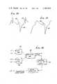
- a circuit showing a cardiac pacer for alternative (1)is set out in greater detail in FIG. 5.
- Conductors E1, E3 from a pair of opposed electrodesprovide input x to differential amplifier 27.
- Conductors E2, E4 from the other pair of opposed electrodesprovide input y to differential amplifier 28.
- the voltage pulses at inputs x and yare shown in FIG. 6.
- the initial large and rapid deflectioncorresponds to the P wave of the electrocardiagram and has been measured in the range of 1 to 6 millivolts.
- the subsequent small and sometimes notchy deflections following the initial large and rapid deflectioncorrespond to the QRS complex.
- the outputs of the differential amplifiersare passed through band pass filters 33, 34, respectively, typically having a pass band in the range of 40 to 500 hertz.
- the filtered outputsare connected to an operational amplifier 35 which may be conventional and which provides a descrete P wave loop as shown in FIG. 7. Alternatively, the operational amplifier may determine the area within the loop resulting from the plot of x versus y.
- the amplitude of xmay vary with respect to that of y and the directions x and y may shift with shifts in position of the catheter within the right atrial chamber.
- the orientation of the loopmay vary in amplitude and direction with such shifts, but the total area would remain substantially constant. See for example, FIG. 8 showing three such loops where the area under the curve of a loop irrespective of sequence or direction of atrial depolarization indicates P wave activity which cannot be confused with ventricular activity. Ventricular activity appears only as a minor deflection within the central area of the loop.
- the signal representing the area within the loopdetermined either by analog or digital means, is an accurate measure of the P wave which is readily discriminated from the QRS complex.
- the remainder of the circuitincludes an interval counter and memory 37, logic circuits for arrhythmia analysis 38, conventional pacer sensing logic 39, and conventional AV sequential pacer circuit 40.
- the pacerrelies on both sensing of atrial depolarizations and sensing of ventricular responses.
- a digital signalis sent from the operational amplifier 35 to the pacer circuit 40 to state that a P wave has been sensed.
- the pacer circuitwould then wait 140 to 200 milliseconds (depending upon the way it is programmed) and if no ventricular depolarization is sensed by the ventricular portion of the electrode catheter, an impulse sufficient to stimulate the ventricle would be generated and delivered. See FIG. 9, where two normally conducted P waves 41, 42 with a normal PR interval are followed by a failure of AV conductions 43. Under this circumstance the pacer would fire in the demand mode with a preset PR interval of approximately 200 milliseconds.
- the operational amplifier 35sends out a specific signal of known characteristics which represents the P wave.
- This signalis fed to interval counter 37 which compares the P to P interval of the sensed beat with the stored interval of the average of the ten prior P wave intervals sensed.
- the interval countermay be combined with logic circuits 38 for arrhythmia analysis with the capability of discriminating atrial premature beats, flutter, fibrillation and paroxysmal atrial tachycardia from appropriate increases in sinus rate.
- the output from the logic circuitsis fed to the AV sequential pacer circuits 40, which may include programmable parameters such as high and low rate limits, PR interval, pulse duration, and pulse amplitude.
- the analog atrial electrogram signals derived from the electrode pairs 21-23 and 22-24may be considered the X and Y input to an operational amplifier which takes the "electrical" area under the loop described by X vs. Y.
- the amplifierwould be a standard operational amplifier which integrates X as a function of Y deriving a digital value. A specific digital value exceeding preset limits would represent "detection" of a P wave and would then activate the P synchronous pacing output circuitry.
- Varying the pulse rate of the signal at E5 as a function of a sensed electrical signalis a well known technology using equipment currently available from commercial sources, including the Cordis Corporation.
- the circuit designis best shown in U.S. Pat. No. to Thaler 4, 091,817, wherein a P wave control, R wave inhibited ventricular stimulation device is described; and is also shown in U.S. Pat. No. to Lin, et al., 4,060,090 wherein the PR interval decreases as a function of the rate of the detected P waves.
- Both of these types of circuitscould be used in the pulse generator of the present invention including item 30 in FIG. 4 and item 40 in FIG. 5.
- P wave synchronous technologyis well known and further details are given in Nathan, et al. Am. J. Cardiol. 11:362-7, 1963; and Kruse, et al., Pace 3:641, 1980.
- the deviation of occurrence of a P wave signal from prior P wave signalsmay be detected and used to initiate a pacing pulse, when such deviation is outside predetermined limits.
- a circuit for performing this functionis shown in FIG. 25, including an interval counter 76 and a comparator 79 for comparing the current P wave to P wave interval (P-P) from a register 77 and the average of ten P-P intervals from an averaging unit 78.
- the comparator outputis connected to a conventional AV delay unit, which in turn is connected to the stimulating pulse generating unit 30 (or 40).
- the output of the detection logic 29will go to the interval counter 76 which will determine each successive P-P interval in msec. This digital information will be computed into a moving average of the 10 previous P-P intervals using standard digital circuitry 78. The current P-P interval from 77 will be compared (digitally) to the current average P-P interval from 78. If there is a ⁇ 10% difference, normal sinus rhythm will be logically assumed, and the currently sensed atrial signal (P wave) will enter a circuit 80 with a variable AV delay and from there to the ventricular stimulating circuits 30.
- a ventricular stimulating pulsewill be generated but with a longer AV delay programmed to vary inversely with the extent of the curtailed cycle. If the current P-P is curtailed by 74%, no ventricular output will be generated.
- the cardiac pacerprovides a stimulating pulse to the heart at a rate which varies to match the rate called for by the body, while at the same time utilizing only a single catheter which is readily inserted and maintained in position.
- a signal which varies as a function of the P waveis produced by the sensing electrode structure adjacent the atrium wall.
- the cathetermay at times lie against the wall, but will usually lie adjacent and in close proximity to the wall. Physical contact between electrodes and atrial myocardium is not required and would probably be detrimental due to progressive fibrosis and signal attenuation.
- This electrode systemsenses and provides a strong P wave signal without sensing QRS complexes and provides such a signal for use with the conventional AV pacer circuit.
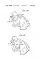
- FIG. 12The position of the catheter of the invention for atrial sensing and ventricle stimulation is shown in greater detail in FIG. 12, wherein various components of the heart are labeled.
- FIG. 13An alternative positioning of the catheter for use in ventricle sensing and ventricle stimulation is shown in FIG. 13, with the sensing electrodes 21-24 in the ventricle near the stimulation electrode.
- This type of operationis generally designated as VVI type pacing.
- VVI type pacingIn ordinary electrode catheter configurations with unipolar stimulating catheters, a unipolar signal derived from the ventricle and the anode located under the chest wall is used for sensing and stimulating.
- bipolar systemsthe two ring electrodes at the ventricular level are used for both sensing and placing.
- QRS complexesThere have been considerable problems with sensing in the ventricle using either of these systems.
- QRS complexesThere have been considerable problems with sensing in the ventricle using either of these systems.
- QRS complexesWith a bipolar system although external signals are less well sensed it is not infrequent that other components of the ventricular repolarization such as T waves are seen, or that ventricular premature depolarizations are not seen by this type of catheter
- sensing and stimulationhas been performed with the same electrode or electrodes.
- the sensing systemsees the stimulation pulse and the stimulation artifact, but not the QRS complex and hence cannot really indicate whether or not there has been any heart response to the delivered electrical stimulus.
- FIG. 13The positioning of FIG. 13 is for a pacing system which utilizes ventricular sensing and ventricular pacing--a standard VVI mode of ventricular pacing wherein as long as the patient remains with a heart rate above the set rate of the pacemaker there is no stimulation. Signals are sensed on electrodes located one or a few centimeters back from the pacing tip and two, three, or four such free floating circumferential electrodes are used to sense the QRS complex. If no QRS complex is sensed within the specified period of time, standard pacemaker logic is utilized to stimulate the right ventricle through the distal electrode.
- sensing systemwhich is independent of the pacing distal electrode. For example, one can judge by looking at the electrogram recorded from the proximal yet still ventricular site whether or not the stimulus delivered at the distal electrode resulted in a ventricular response. This is illustrated in the electrogram of FIG. 20.
- the catheter used for producing this electrogramhad a pacing electrode at the tip to provide the stimulus pulse, and three sensing electrodes positioned about the catheter equidistant from the tip at a distance such that the electrodes were in the ventricle, as shown in FIG. 13.
- the sharp spike 56is the stimulus pulse produced by the unipolar pacer, and the more complex pulse 57 is the sensed heart action, namely the QRS complex.
- the heart actionis produced by the stimulus and occurs within 15 to 20 milliseconds.
- the electrogramshows that the electrode configuration of the invention will sense this heart action.
- the pulse group 59 at the right of FIG. 20shows heart action occurring prior to the stimulus, with the stimulus producing no heart action because it occurs during the refractory period, that is, the period after heart action when another heart action can not be generated.
- the evoked QRSwas obscured by the stimulus artifact.
- the stimulus artifactappears as a very discrete spike 56 and the QRS is a large amplitude three to five millivolt signal 57 clearly distinguishable from the stimulus artifact.
- FIGS. 21 and 22are two electrograms taken on the same patient one after the other, each showing an x trace, with the time scale compressed over that used in FIG. 20.
- the trace in FIG. 21was obtained with a catheter using the stimulating electrode for the sensing also, a conventional approach.
- FIG. 21shows a stimulus 56 and the resulting sensed wave form 60.
- ventricular stimulationhad resulted in a response.
- the trace in FIG. 22was made with this same standard catheter.
- Sensed QRS complexesare indicated by 57.
- a stimulusis applied to the ventricle at a time when it can not respond--i.e is refractory.
- wave form 60is identical whether or not a ventricular response has occurred.
- standard cathetersare incapable of judging whether stimuli have resulted in responses.
- stimulus 56clearly results in response 57 during complex 58, but there is no response to stimulus 56 in complex 59.
- the pacing system as shown in FIG. 20can determine whether or not there is heart response to the stimulus, even though it occurs within milliseconds of the stimulus.
- the pacemakerIn operation at specified times the pacemaker would decrease the current output at the distal pacing electrode and judge whether or not a response occurred as sensed by the sensing electrodes 20-24. When a response was not sensed, the pacemaker would recognize the lack of a QRS complex and simply double the stimulation threshold to the stimulation electrode 20. This would allow for maximum pacemaker battery longevity since stimulation threshold may be a constantly changing measurement. If desired the input from the sensing electrodes can be blanked at the time of the stimulation pulse. However even without this addition, QRS complexes are readily distinguished from stimulus artifacts.
- FIG. 23A typical circuit for a VVI pacemaker is shown in FIG. 23, which is similar to that shown in FIG. 4.
- Leads E1 and E3are connected as inputs to a differential amplifier 63, and leads E2 and E4 are connected as inputs to another differential amplifier 64.
- the amplifier outputsare connected to an operational amplifier 65 which may perform summing or more complex manipulations on the signals as desired.
- the output of the operational amplifieris the desired QRS signal, which is provided as an input to a standard VVI circuit 66.
- a pulse generator 67which provides the stimulus pulse to electrode E5.
- the standard VVI circuitprovides for blocking sensing for about 300 milliseconds after the stimulus pulse, which is a necessary delay because the QRS complex signal is not discriminated from other voltages with the conventional catheter. After the delay, the standard circuit looks for heart action and if it is sensed, the timing circuit is reset. if it is not sensed, a stimulus pulse is provided. When using the catheter of the present application, the delay can be reduced from 300 milliseconds to 10 milliseconds, permitting sensing immediately following the stimulus.
- Ventricular tachycardiais a condition wherein the heart beats at a very high rate and usually is corrected by applying one or more stimulating pulses to the heart to break up the rhythm of the high rate.
- the high rate heart actionhas been sensed and a stimulating pulse has been provided.
- the pacing systemhas not been able to measure the result of the stimulatng pulse.
- the catheter utilized with the VVI configuration of the present inventioncan be utilized with a tachy converting pacemaker to sense heart response to a stimulus even during tachycardia and indicate whether or not the stimulus has evoked a response.
- the catheter of the inventionalso may be used for sensing P waves at the atrial level in patients with intermittent sinus node dysfunction.
- these patientswhose AV conduction is normal, the problem has to do with intermittent failure of the dominant pacemaker of the heart to fire. Whereas they have a normal response to rates at the atrial level, intermittently the sinus node fails to result in atrial depolarization, and the rate abruptly falls.
- the electronicscan be designed so that when P waves fail to occur at a predetermined rate, the atrium itself could be stimulated. This would be termed an AAI pacemaker, that is atrial sensing and atrial stimulating or inhibited pacemaker.
- Such a pacemakerwould have some definite therapeutic advantages over the typical VVI pacemaker currently used for intermittent sinus node dysfunction.
- FIG. 14A modification of the standard J-shaped atrial pacing electrode to incorporate the present invention for AAI pacing is illustrated in FIG. 14. There is a ridge 50 in this electrode which causes it to retain its J configuration.
- the pacing electrode 20is lodged within the right atrial appendage.
- the sensing electrodes 21 through 24are in the high lateral right atrium quite separate from the distal pacing electrode. This type of pacemaker would be utilized with patients having intermittent sinus node dysfunction. At times when their atrial rate exceeded the predetermined rate of the pacemaker, signals sensed by electrodes 21 through 24 would inhibit any output through the pacing circuit.
- the rate of the normal sinus node pacemakerwould be applied to the right atrial appendage at a rate predetermined by the electronic pacemaker.
- This ratemight be simply a fixed number, e.g. 75, or might be a function of the previous sinus rate such that where the heart rate precedent to the loss of P wave was 80, the atria would be paced at this rate until such time as the sinus node again exceeded the rate of the pacemaker itself.
- the right atrial appendageoverlies the pulmonary outflow tract.
- signals sensed at the conventional tip electrodefrequently reflect as large a QRS complex as they do a P wave.
- An electrogram for this conditionwould be essentially the same as that of FIG.
- a circuit for AAI pacingmay be the same as that of FIG. 23, except that a standard AAI circuit is used in place of the standard VVI circuit 66, and that the sensed signal is a P wave signal rather than a QRS signal.
- the configuration illustrated in FIG. 15is a modification of the previous atrial sensing atrial pacing pacemaker of FIG. 14 in that the stimulating electrode is located either one centimeter back from the tip within the coronary sinus 20a or three or four centimeters back just at the origin of the coronary sinus 20b. Again the sensing electrodes in this atrial sensing atrial pacing catheter would be located in the high lateral right atrium.
- the problem with currently existing coronary sinus pacemakersis that the QRS complex is of equal or greater amplitude than the P wave as sensed from electrodes either one centimeter of four centimeters back from the tip of a catheter located in the coronary sinus. Thus, adequate sensing of P waves has been impossible. With the sensing electrodes 20-24 located circumferentially around the catheter in the high lateral right atrium, this problem would be obviated.
- the configuration of FIG. 15may be operated in the same manner as that of FIG. 14.
Landscapes
- Health & Medical Sciences (AREA)
- Heart & Thoracic Surgery (AREA)
- Cardiology (AREA)
- Life Sciences & Earth Sciences (AREA)
- Public Health (AREA)
- Engineering & Computer Science (AREA)
- Biomedical Technology (AREA)
- Nuclear Medicine, Radiotherapy & Molecular Imaging (AREA)
- Radiology & Medical Imaging (AREA)
- Animal Behavior & Ethology (AREA)
- General Health & Medical Sciences (AREA)
- Veterinary Medicine (AREA)
- Physiology (AREA)
- Biophysics (AREA)
- Vascular Medicine (AREA)
- Electrotherapy Devices (AREA)
Abstract
Description
Claims (42)
Applications Claiming Priority (1)
| Application Number | Priority Date | Filing Date | Title |
|---|---|---|---|
| US11940680A | 1980-02-07 | 1980-02-07 |
Related Parent Applications (1)
| Application Number | Title | Priority Date | Filing Date |
|---|---|---|---|
| US11940680AContinuation-In-Part | 1980-02-07 | 1980-02-07 |
Publications (1)
| Publication Number | Publication Date |
|---|---|
| US4365639Atrue US4365639A (en) | 1982-12-28 |
Family
ID=22384246
Family Applications (1)
| Application Number | Title | Priority Date | Filing Date |
|---|---|---|---|
| US06/242,705Expired - LifetimeUS4365639A (en) | 1980-02-07 | 1981-03-11 | Catheter, cardiac pacemaker and method of pacing |
Country Status (1)
| Country | Link |
|---|---|
| US (1) | US4365639A (en) |
Cited By (234)
| Publication number | Priority date | Publication date | Assignee | Title |
|---|---|---|---|---|
| FR2533817A1 (en)* | 1982-08-05 | 1984-04-06 | Applied Cardiac Electrophys | Internal ECG detector using angled dual electrode |
| EP0113854A1 (en)* | 1982-12-21 | 1984-07-25 | Siemens Aktiengesellschaft | Bifocal pacemaker with two unipolar electrodes |
| EP0118306A1 (en)* | 1983-03-04 | 1984-09-12 | Medtronic, Inc. | An atrial synchronized pacemaker having an adaptive atrial refractory period |
| EP0159753A1 (en)* | 1984-04-16 | 1985-10-30 | Eliezer A. Astrinski | Cardiac lead |
| EP0087756A3 (en)* | 1982-02-26 | 1986-03-12 | Siemens Aktiengesellschaft | Av-sequential heart pacemaker |
| US4579119A (en)* | 1983-11-18 | 1986-04-01 | Cordis Corporation | Method and apparatus for multiplexed dipole/quadrupole for stimulation/sensing |
| US4608986A (en)* | 1984-10-01 | 1986-09-02 | Cordis Corporation | Pacing lead with straight wire conductors |
| US4630611A (en)* | 1981-02-02 | 1986-12-23 | Medtronic, Inc. | Orthogonally-sensing lead |
| US4662382A (en)* | 1985-01-16 | 1987-05-05 | Intermedics, Inc. | Pacemaker lead with enhanced sensitivity |
| US4712554A (en)* | 1985-04-08 | 1987-12-15 | Baylor College Of Medicine | Electronic system to distinguish between sinus and nonsinus atrial depolarizations which do not stimulate ventricular depolarizations in response to nonsinus atrial depolarizations |
| US4726379A (en)* | 1985-11-14 | 1988-02-23 | Cardiac Control Systems, Inc. | Cardiac pacer with switching circuit for isolation |
| US4750494A (en)* | 1981-05-12 | 1988-06-14 | Medtronic, Inc. | Automatic implantable fibrillation preventer |
| US4754753A (en)* | 1981-05-12 | 1988-07-05 | Medtronic, Inc. | System for sensing electrical depolarization wave signals and their direction |
| US4774951A (en)* | 1985-06-19 | 1988-10-04 | Peter Osypka | Surgically implantable cardiac pacemaker |
| US4777955A (en)* | 1987-11-02 | 1988-10-18 | Cordis Corporation | Left ventricle mapping probe |
| US4892102A (en)* | 1984-04-16 | 1990-01-09 | Astrinsky Eliezer A | Cardiac pacing and/or sensing lead and method of use |
| WO1990000878A1 (en)* | 1988-07-27 | 1990-02-08 | Ep Technologies, Inc. | Apparatus and method for recording monophasic potentials |
| US4922912A (en)* | 1987-10-21 | 1990-05-08 | Hideto Watanabe | MAP catheter |
| US4955382A (en)* | 1984-03-06 | 1990-09-11 | Ep Technologies | Apparatus and method for recording monophasic action potentials from an in vivo heart |
| EP0350282A3 (en)* | 1988-07-05 | 1990-10-10 | Cardiac Control Systems, Inc. | Pacemaker catheter |
| US5078133A (en)* | 1989-05-03 | 1992-01-07 | Eckhard Alt | Pacemaker methods and pacing control systems operable from a preferred one of at least two pacing rate control signals |
| WO1992004074A1 (en)* | 1990-09-10 | 1992-03-19 | Ep Technologies Inc. | Apparatus for pacing an in vivo heart |
| US5127403A (en)* | 1988-07-05 | 1992-07-07 | Cardiac Control Systems, Inc. | Pacemaker catheter utilizing bipolar electrodes spaced in accordance to the length of a heart depolarization signal |
| US5156149A (en)* | 1990-08-10 | 1992-10-20 | Medtronic, Inc. | Sensor for detecting cardiac depolarizations particularly adapted for use in a cardiac pacemaker |
| US5170785A (en)* | 1989-05-03 | 1992-12-15 | Dr. Eckhard Alt | Rate varying pacemaker apparatus and method for deriving a preferred one of different patient activity control signals |
| US5215103A (en)* | 1986-11-14 | 1993-06-01 | Desai Jawahar M | Catheter for mapping and ablation and method therefor |
| US5226414A (en)* | 1991-07-24 | 1993-07-13 | Intermedics, Inc. | Implantable cardiac pacemaker with extended atrial sensing |
| US5231995A (en)* | 1986-11-14 | 1993-08-03 | Desai Jawahar M | Method for catheter mapping and ablation |
| WO1994015528A1 (en)* | 1993-01-08 | 1994-07-21 | Goldreyer Bruce N | Electrophysiological sensing, for mapping, pacing and ablating |
| US5331966A (en)* | 1991-04-05 | 1994-07-26 | Medtronic, Inc. | Subcutaneous multi-electrode sensing system, method and pacer |
| US5348021A (en)* | 1992-03-31 | 1994-09-20 | Incontrol, Inc. | Apparatus and method for reliably detecting a depolarization activation wave of the heart and atrial defibrillator utilizing same |
| US5365926A (en)* | 1986-11-14 | 1994-11-22 | Desai Jawahar M | Catheter for mapping and ablation and method therefor |
| US5383917A (en)* | 1991-07-05 | 1995-01-24 | Jawahar M. Desai | Device and method for multi-phase radio-frequency ablation |
| WO1995008366A1 (en)* | 1993-09-22 | 1995-03-30 | Siemens Pacesetter, Inc. | Pacing and defibrillating lead with sensing capability |
| US5413592A (en)* | 1993-03-26 | 1995-05-09 | Intermedics, Inc. | Cardiac pacemaker with automatic parameter adjustment |
| US5423878A (en)* | 1984-03-06 | 1995-06-13 | Ep Technologies, Inc. | Catheter and associated system for pacing the heart |
| US5433729A (en)* | 1991-04-12 | 1995-07-18 | Incontrol, Inc. | Atrial defibrillator, lead systems, and method |
| US5433198A (en)* | 1993-03-11 | 1995-07-18 | Desai; Jawahar M. | Apparatus and method for cardiac ablation |
| US5562619A (en)* | 1993-08-19 | 1996-10-08 | Boston Scientific Corporation | Deflectable catheter |
| WO1997012548A1 (en) | 1995-10-06 | 1997-04-10 | Cordis Webster, Inc. | Split tip electrode catheter |
| US5620481A (en)* | 1991-07-05 | 1997-04-15 | Desai; Jawahar M. | Device for multi-phase radio-frequency ablation |
| US5657755A (en)* | 1993-03-11 | 1997-08-19 | Desai; Jawahar M. | Apparatus and method for cardiac ablation |
| US5730142A (en)* | 1996-12-04 | 1998-03-24 | Medtronic, Inc. | Method and apparatus for detecting tachycardia |
| US5749901A (en)* | 1994-03-29 | 1998-05-12 | Pacesetter, Inc. | Method and apparatus for delivering defibrillation shocks with improved effectiveness |
| US5755761A (en)* | 1996-04-26 | 1998-05-26 | Pharmatarget, Inc. | Atrial pacing catheter and method having multiple electrodes in the right atrium and coronary sinus |
| US5755739A (en)* | 1996-12-04 | 1998-05-26 | Medtronic, Inc. | Adaptive and morphological system for discriminating P-waves and R-waves inside the human body |
| US5837001A (en)* | 1995-12-08 | 1998-11-17 | C. R. Bard | Radio frequency energy delivery system for multipolar electrode catheters |
| US5843132A (en)* | 1996-10-07 | 1998-12-01 | Ilvento; Joseph P. | Self-contained, self-powered temporary intravenous pacing catheter assembly |
| US5871508A (en)* | 1997-08-06 | 1999-02-16 | Medtronic, Inc. | Apparatus for cardiac pacing in transplant |
| US5978704A (en)* | 1997-06-03 | 1999-11-02 | Uab Research Foundation | Method and apparatus for treating cardiac arrhythmia |
| US5987354A (en)* | 1996-08-13 | 1999-11-16 | Uab Research Foundation | Dual shock atrial defibrillation apparatus |
| US6006131A (en)* | 1996-08-13 | 1999-12-21 | Uab Research Foundation | Dual current pathway atrial defibrillation apparatus |
| US6047217A (en)* | 1998-01-15 | 2000-04-04 | Intermedics Inc. | Cardiac lead with improved polymer-to-metal joint |
| US6064902A (en)* | 1998-04-16 | 2000-05-16 | C.R. Bard, Inc. | Pulmonary vein ablation catheter |
| USH1905H (en)* | 1997-03-21 | 2000-10-03 | Medtronic, Inc. | Mechanism for adjusting the exposed surface area and position of an electrode along a lead body |
| WO2000069334A1 (en) | 1999-05-13 | 2000-11-23 | Daig Corporation | Device for the mapping of cardiac arrhytmia foci |
| US6241724B1 (en) | 1993-10-19 | 2001-06-05 | Ep Technologies, Inc. | Systems and methods for creating lesions in body tissue using segmented electrode assemblies |
| US6484057B2 (en) | 2000-12-21 | 2002-11-19 | Uab Research Foundation | Pacing methods and devices for treating cardiac arrhythmias and fibrillation |
| US6522904B1 (en)* | 1999-03-30 | 2003-02-18 | Impulse Dynamics N.V. | Bipolar sensor for muscle tissue action potential duration estimation |
| US6522905B2 (en) | 1993-03-11 | 2003-02-18 | Jawahar M. Desai | Apparatus and method for cardiac ablation |
| US20030078484A1 (en)* | 1997-09-12 | 2003-04-24 | Alfred E. Mann Foundation For Scientific Research | Substrate sensor |
| US20030105501A1 (en)* | 2001-12-03 | 2003-06-05 | Warman Eduardo N. | Shaped lead with electrodes |
| WO2003047687A2 (en) | 2001-12-03 | 2003-06-12 | Medtronic,Inc. | Shaped lead with electrodes |
| US6584352B2 (en) | 2000-12-27 | 2003-06-24 | Medtronic, Inc. | Leadless fully automatic pacemaker follow-up |
| US20030199868A1 (en)* | 1991-07-05 | 2003-10-23 | Desai Jawahar M. | Device and method for multi-phase radio-frequency ablation |
| US6640136B1 (en) | 2001-09-12 | 2003-10-28 | Pacesetters, Inc. | Implantable cardiac stimulation device with automatic electrode selection for avoiding cross-chamber stimulation |
| US6654637B2 (en) | 2001-04-30 | 2003-11-25 | Medtronic, Inc. | Method and system for ventricular fusion prevention |
| US20030220676A1 (en)* | 2002-05-21 | 2003-11-27 | John R. Helland | Electrode arrangements for body implantable pacing and sensing leads |
| US20040024421A1 (en)* | 2002-07-31 | 2004-02-05 | Ideker Raymond E. | Pacing methods and devices using feedback controlled timing |
| US20040049118A1 (en)* | 2002-09-10 | 2004-03-11 | Ideker Raymond E. | Methods, systems and computer program products for treating fibrillation in a patient based on the presence of fibrillation following administration of defibrillation therapy |
| US20040049232A1 (en)* | 2002-09-10 | 2004-03-11 | Ideker Raymond E. | Post-defibrillation pacing methods and devices |
| US20040049117A1 (en)* | 2002-09-10 | 2004-03-11 | Ideker Raymond E. | Devices for detecting the presence of cardiac activity following administration of defibrillation therapy |
| US6738673B2 (en) | 1986-11-14 | 2004-05-18 | Jawahar M. Desai | Method for catheter mapping and ablation |
| US20040167578A1 (en)* | 1999-03-12 | 2004-08-26 | Warren Jay A. | Cardiac rhythm management system with time-dependent frequency response |
| US6799064B1 (en) | 1999-05-13 | 2004-09-28 | St. Jude Medical, Daig Division | Device for the mapping of cardiac arrhythmia foci |
| US20040230275A1 (en)* | 2003-05-15 | 2004-11-18 | Marshall Mark T. | Medical system including a novel bipolar pacing and sensing pair |
| US20040230276A1 (en)* | 2003-05-15 | 2004-11-18 | Marshall Mark T. | Medical system including a novel bipolar pacing pair |
| US20040267328A1 (en)* | 2003-06-24 | 2004-12-30 | Medtronic, Inc. | Electrode selection system for medical electrical leads |
| WO2005035053A1 (en)* | 2003-10-07 | 2005-04-21 | Medtronic, Inc. | Extra-systolic stimulation therapy delivery and sensing via different electrode sets |
| US20060136001A1 (en)* | 2004-12-20 | 2006-06-22 | Action Medical, Inc. | Ventricular pacing |
| US20060155334A1 (en)* | 2003-03-13 | 2006-07-13 | Ideker Raymond E | Methods and systems for reducing discomfort from cardiac defibrillation shocks |
| US20070010752A1 (en)* | 2003-04-10 | 2007-01-11 | Pentti Korhonen | System and method for analysing the p-wave of an ecg-signal |
| US20070049846A1 (en)* | 2005-08-24 | 2007-03-01 | C.R.Bard, Inc. | Stylet Apparatuses and Methods of Manufacture |
| US7328066B1 (en) | 2003-03-28 | 2008-02-05 | Pacesetter, Inc. | Implantable cardiac stimulation device, system and method that identifies and prevents impending arrhythmias of the atria |
| US20080319496A1 (en)* | 2004-12-20 | 2008-12-25 | Qingsheng Zhu | Endocardial Pacing Devices and Methods Useful for Resynchronization and Defibrillation |
| US20080319500A1 (en)* | 2004-12-20 | 2008-12-25 | Qingsheng Zhu | Systems, Devices and Methods Relating to Endocardial Pacing for Resynchronization |
| US20080319501A1 (en)* | 2004-12-20 | 2008-12-25 | Qingsheng Zhu | Systems, Devices and Methods for Monitoring Efficiency of Pacing |
| US20090005830A1 (en)* | 2004-12-20 | 2009-01-01 | Qingsheng Zhu | Endocardial Pacing Relating to Conduction Abnormalities |
| US20090054942A1 (en)* | 2004-12-20 | 2009-02-26 | Qingsheng Zhu | Methods, devices and systems for single-chamber pacing using a dual-chamber pacing device |
| US20090099635A1 (en)* | 2007-10-16 | 2009-04-16 | Foster Arthur J | Stimulation and sensing lead with non-coiled wire construction |
| US20090157156A1 (en)* | 2007-12-14 | 2009-06-18 | Foster Arthur J | Fixation helix and multipolar medical electrode |
| US7587239B1 (en) | 2003-09-24 | 2009-09-08 | Pacesetter, Inc. | Cardiac pacemaker system, lead and method for rejecting far-field signals |
| US20100004706A1 (en)* | 2008-07-01 | 2010-01-07 | Mokelke Eric A | Pacing system controller integrated into indeflator |
| US20100036227A1 (en)* | 2007-11-26 | 2010-02-11 | C. R. Bard, Inc. | Apparatus and display methods relating to intravascular placement of a catheter |
| US20100094116A1 (en)* | 2008-10-07 | 2010-04-15 | Lucent Medical Systems, Inc. | Percutaneous magnetic gastrostomy |
| US7734344B2 (en) | 2003-12-02 | 2010-06-08 | Uab Research Foundation | Methods, systems and computer program products to inhibit ventricular fibrillation during cardiopulmonary resuscitation |
| US20100204569A1 (en)* | 2007-11-26 | 2010-08-12 | C. R. Bard, Inc. | System for placement of a catheter including a signal-generating stylet |
| US20100318026A1 (en)* | 2009-06-12 | 2010-12-16 | Romedex International Srl | Devices and Methods for Endovascular Electrography |
| US20100317981A1 (en)* | 2009-06-12 | 2010-12-16 | Romedex International Srl | Catheter Tip Positioning Method |
| US20100331712A1 (en)* | 2006-10-23 | 2010-12-30 | Bard Access Systems, Inc. | Method of locating the tip of a central venous catheter |
| US20110015533A1 (en)* | 2007-11-26 | 2011-01-20 | C.R. Bard, Inc. | Stylets for use with apparatus for intravascular placement of a catheter |
| US7962208B2 (en) | 2005-04-25 | 2011-06-14 | Cardiac Pacemakers, Inc. | Method and apparatus for pacing during revascularization |
| US20110196248A1 (en)* | 2009-06-12 | 2011-08-11 | Bard Access Systems, Inc. | Apparatus and method for catheter navigation and tip location |
| US8050756B2 (en) | 2004-12-20 | 2011-11-01 | Cardiac Pacemakers, Inc. | Circuit-based devices and methods for pulse control of endocardial pacing in cardiac rhythm management |
| US20120143298A1 (en)* | 2010-12-02 | 2012-06-07 | Just Dale E | Catheter electrode assemblies and methods of construction therefor |
| US8244352B2 (en) | 2008-06-19 | 2012-08-14 | Cardiac Pacemakers, Inc. | Pacing catheter releasing conductive liquid |
| US8326423B2 (en) | 2004-12-20 | 2012-12-04 | Cardiac Pacemakers, Inc. | Devices and methods for steering electrical stimulation in cardiac rhythm management |
| US8388541B2 (en) | 2007-11-26 | 2013-03-05 | C. R. Bard, Inc. | Integrated system for intravascular placement of a catheter |
| US8388546B2 (en) | 2006-10-23 | 2013-03-05 | Bard Access Systems, Inc. | Method of locating the tip of a central venous catheter |
| US8423139B2 (en) | 2004-12-20 | 2013-04-16 | Cardiac Pacemakers, Inc. | Methods, devices and systems for cardiac rhythm management using an electrode arrangement |
| US8457738B2 (en) | 2008-06-19 | 2013-06-04 | Cardiac Pacemakers, Inc. | Pacing catheter for access to multiple vessels |
| US8478382B2 (en) | 2008-02-11 | 2013-07-02 | C. R. Bard, Inc. | Systems and methods for positioning a catheter |
| US8565880B2 (en) | 2010-04-27 | 2013-10-22 | Cardiac Pacemakers, Inc. | His-bundle capture verification and monitoring |
| US20130338530A1 (en)* | 2003-02-21 | 2013-12-19 | Ghassan S. Kassab | Body lumen junction localization |
| US8639357B2 (en) | 2008-06-19 | 2014-01-28 | Cardiac Pacemakers, Inc. | Pacing catheter with stent electrode |
| US8649852B2 (en) | 2011-05-02 | 2014-02-11 | Medtronic, Inc. | Method of signal enhancement for ECG devices |
| USD699359S1 (en) | 2011-08-09 | 2014-02-11 | C. R. Bard, Inc. | Ultrasound probe head |
| US8688234B2 (en) | 2008-12-19 | 2014-04-01 | Cardiac Pacemakers, Inc. | Devices, methods, and systems including cardiac pacing |
| US8734388B2 (en) | 2011-04-01 | 2014-05-27 | Rutgers, The State University Of New Jersey | Catheter for minimally invasive cardiac pacing surgery and method of use |
| US8801693B2 (en) | 2010-10-29 | 2014-08-12 | C. R. Bard, Inc. | Bioimpedance-assisted placement of a medical device |
| US20140243816A1 (en)* | 2005-12-30 | 2014-08-28 | Biosense Webster, Inc. | System and method for selectively energizing catheter electrodes |
| US8874207B2 (en) | 2005-12-23 | 2014-10-28 | Cardiac Pacemakers, Inc. | Method and apparatus for tissue protection against ischemia using remote conditioning |
| USD724745S1 (en) | 2011-08-09 | 2015-03-17 | C. R. Bard, Inc. | Cap for an ultrasound probe |
| US9002467B2 (en) | 2005-05-18 | 2015-04-07 | Cardiac Pacemakers, Inc. | Modular antitachyarrhythmia therapy system |
| US9037235B2 (en) | 2008-06-19 | 2015-05-19 | Cardiac Pacemakers, Inc. | Pacing catheter with expandable distal end |
| US9211107B2 (en) | 2011-11-07 | 2015-12-15 | C. R. Bard, Inc. | Ruggedized ultrasound hydrogel insert |
| WO2016053585A1 (en)* | 2014-09-29 | 2016-04-07 | New York Institute Of Technology | Catheter for use in recording his electrogram alternans and application to various conditions |
| US9409012B2 (en) | 2008-06-19 | 2016-08-09 | Cardiac Pacemakers, Inc. | Pacemaker integrated with vascular intervention catheter |
| US9456766B2 (en) | 2007-11-26 | 2016-10-04 | C. R. Bard, Inc. | Apparatus for use with needle insertion guidance system |
| US9480834B2 (en) | 2012-05-08 | 2016-11-01 | Cardiac Pacemakers, Inc. | Multipolar conductor for an implantable medical device |
| US9492097B2 (en) | 2007-11-26 | 2016-11-15 | C. R. Bard, Inc. | Needle length determination and calibration for insertion guidance system |
| US9521961B2 (en) | 2007-11-26 | 2016-12-20 | C. R. Bard, Inc. | Systems and methods for guiding a medical instrument |
| US9526909B2 (en) | 2014-08-28 | 2016-12-27 | Cardiac Pacemakers, Inc. | Medical device with triggered blanking period |
| US9532724B2 (en) | 2009-06-12 | 2017-01-03 | Bard Access Systems, Inc. | Apparatus and method for catheter navigation using endovascular energy mapping |
| US9554716B2 (en) | 2007-11-26 | 2017-01-31 | C. R. Bard, Inc. | Insertion guidance system for needles and medical components |
| US9592391B2 (en) | 2014-01-10 | 2017-03-14 | Cardiac Pacemakers, Inc. | Systems and methods for detecting cardiac arrhythmias |
| US9649048B2 (en) | 2007-11-26 | 2017-05-16 | C. R. Bard, Inc. | Systems and methods for breaching a sterile field for intravascular placement of a catheter |
| US9669230B2 (en) | 2015-02-06 | 2017-06-06 | Cardiac Pacemakers, Inc. | Systems and methods for treating cardiac arrhythmias |
| US9839372B2 (en) | 2014-02-06 | 2017-12-12 | C. R. Bard, Inc. | Systems and methods for guidance and placement of an intravascular device |
| US9853743B2 (en) | 2015-08-20 | 2017-12-26 | Cardiac Pacemakers, Inc. | Systems and methods for communication between medical devices |
| US9901714B2 (en) | 2008-08-22 | 2018-02-27 | C. R. Bard, Inc. | Catheter assembly including ECG sensor and magnetic assemblies |
| US9956414B2 (en) | 2015-08-27 | 2018-05-01 | Cardiac Pacemakers, Inc. | Temporal configuration of a motion sensor in an implantable medical device |
| US9968787B2 (en) | 2015-08-27 | 2018-05-15 | Cardiac Pacemakers, Inc. | Spatial configuration of a motion sensor in an implantable medical device |
| US10029107B1 (en) | 2017-01-26 | 2018-07-24 | Cardiac Pacemakers, Inc. | Leadless device with overmolded components |
| US10046139B2 (en) | 2010-08-20 | 2018-08-14 | C. R. Bard, Inc. | Reconfirmation of ECG-assisted catheter tip placement |
| US10050700B2 (en) | 2015-03-18 | 2018-08-14 | Cardiac Pacemakers, Inc. | Communications in a medical device system with temporal optimization |
| US10046167B2 (en) | 2015-02-09 | 2018-08-14 | Cardiac Pacemakers, Inc. | Implantable medical device with radiopaque ID tag |
| US10065041B2 (en) | 2015-10-08 | 2018-09-04 | Cardiac Pacemakers, Inc. | Devices and methods for adjusting pacing rates in an implantable medical device |
| US10092760B2 (en) | 2015-09-11 | 2018-10-09 | Cardiac Pacemakers, Inc. | Arrhythmia detection and confirmation |
| US10137305B2 (en) | 2015-08-28 | 2018-11-27 | Cardiac Pacemakers, Inc. | Systems and methods for behaviorally responsive signal detection and therapy delivery |
| US10159842B2 (en) | 2015-08-28 | 2018-12-25 | Cardiac Pacemakers, Inc. | System and method for detecting tamponade |
| US10159531B2 (en) | 2012-04-05 | 2018-12-25 | C. R. Bard, Inc. | Apparatus and methods relating to intravascular positioning of distal end of catheter |
| US10183170B2 (en) | 2015-12-17 | 2019-01-22 | Cardiac Pacemakers, Inc. | Conducted communication in a medical device system |
| US10213610B2 (en) | 2015-03-18 | 2019-02-26 | Cardiac Pacemakers, Inc. | Communications in a medical device system with link quality assessment |
| US10220213B2 (en) | 2015-02-06 | 2019-03-05 | Cardiac Pacemakers, Inc. | Systems and methods for safe delivery of electrical stimulation therapy |
| US10226631B2 (en) | 2015-08-28 | 2019-03-12 | Cardiac Pacemakers, Inc. | Systems and methods for infarct detection |
| US10328272B2 (en) | 2016-05-10 | 2019-06-25 | Cardiac Pacemakers, Inc. | Retrievability for implantable medical devices |
| US10349890B2 (en) | 2015-06-26 | 2019-07-16 | C. R. Bard, Inc. | Connector interface for ECG-based catheter positioning system |
| US10350423B2 (en) | 2016-02-04 | 2019-07-16 | Cardiac Pacemakers, Inc. | Delivery system with force sensor for leadless cardiac device |
| US10357159B2 (en) | 2015-08-20 | 2019-07-23 | Cardiac Pacemakers, Inc | Systems and methods for communication between medical devices |
| US10391319B2 (en) | 2016-08-19 | 2019-08-27 | Cardiac Pacemakers, Inc. | Trans septal implantable medical device |
| US10413211B2 (en) | 2003-02-21 | 2019-09-17 | 3Dt Holdings, Llc | Systems, devices, and methods for mapping organ profiles |
| US10413733B2 (en) | 2016-10-27 | 2019-09-17 | Cardiac Pacemakers, Inc. | Implantable medical device with gyroscope |
| US10426962B2 (en) | 2016-07-07 | 2019-10-01 | Cardiac Pacemakers, Inc. | Leadless pacemaker using pressure measurements for pacing capture verification |
| US10434317B2 (en) | 2016-10-31 | 2019-10-08 | Cardiac Pacemakers, Inc. | Systems and methods for activity level pacing |
| US10434314B2 (en) | 2016-10-27 | 2019-10-08 | Cardiac Pacemakers, Inc. | Use of a separate device in managing the pace pulse energy of a cardiac pacemaker |
| US10449330B2 (en) | 2007-11-26 | 2019-10-22 | C. R. Bard, Inc. | Magnetic element-equipped needle assemblies |
| US10463305B2 (en) | 2016-10-27 | 2019-11-05 | Cardiac Pacemakers, Inc. | Multi-device cardiac resynchronization therapy with timing enhancements |
| US10512784B2 (en) | 2016-06-27 | 2019-12-24 | Cardiac Pacemakers, Inc. | Cardiac therapy system using subcutaneously sensed P-waves for resynchronization pacing management |
| US10524685B2 (en) | 2003-02-21 | 2020-01-07 | 3Dt Holdings, Llc | Methods for generating luminal organ profiles using impedance |
| US10524691B2 (en) | 2007-11-26 | 2020-01-07 | C. R. Bard, Inc. | Needle assembly including an aligned magnetic element |
| US10561330B2 (en) | 2016-10-27 | 2020-02-18 | Cardiac Pacemakers, Inc. | Implantable medical device having a sense channel with performance adjustment |
| US10583301B2 (en) | 2016-11-08 | 2020-03-10 | Cardiac Pacemakers, Inc. | Implantable medical device for atrial deployment |
| US10583303B2 (en) | 2016-01-19 | 2020-03-10 | Cardiac Pacemakers, Inc. | Devices and methods for wirelessly recharging a rechargeable battery of an implantable medical device |
| US10617874B2 (en) | 2016-10-31 | 2020-04-14 | Cardiac Pacemakers, Inc. | Systems and methods for activity level pacing |
| US10632313B2 (en) | 2016-11-09 | 2020-04-28 | Cardiac Pacemakers, Inc. | Systems, devices, and methods for setting cardiac pacing pulse parameters for a cardiac pacing device |
| US10639486B2 (en) | 2016-11-21 | 2020-05-05 | Cardiac Pacemakers, Inc. | Implantable medical device with recharge coil |
| US10639008B2 (en) | 2009-10-08 | 2020-05-05 | C. R. Bard, Inc. | Support and cover structures for an ultrasound probe head |
| US10668294B2 (en) | 2016-05-10 | 2020-06-02 | Cardiac Pacemakers, Inc. | Leadless cardiac pacemaker configured for over the wire delivery |
| US10688304B2 (en) | 2016-07-20 | 2020-06-23 | Cardiac Pacemakers, Inc. | Method and system for utilizing an atrial contraction timing fiducial in a leadless cardiac pacemaker system |
| US10722720B2 (en) | 2014-01-10 | 2020-07-28 | Cardiac Pacemakers, Inc. | Methods and systems for improved communication between medical devices |
| US10737102B2 (en) | 2017-01-26 | 2020-08-11 | Cardiac Pacemakers, Inc. | Leadless implantable device with detachable fixation |
| US10751509B2 (en) | 2007-11-26 | 2020-08-25 | C. R. Bard, Inc. | Iconic representations for guidance of an indwelling medical device |
| US10758737B2 (en) | 2016-09-21 | 2020-09-01 | Cardiac Pacemakers, Inc. | Using sensor data from an intracardially implanted medical device to influence operation of an extracardially implantable cardioverter |
| US10758724B2 (en) | 2016-10-27 | 2020-09-01 | Cardiac Pacemakers, Inc. | Implantable medical device delivery system with integrated sensor |
| US10765871B2 (en) | 2016-10-27 | 2020-09-08 | Cardiac Pacemakers, Inc. | Implantable medical device with pressure sensor |
| US10780278B2 (en) | 2016-08-24 | 2020-09-22 | Cardiac Pacemakers, Inc. | Integrated multi-device cardiac resynchronization therapy using P-wave to pace timing |
| US10821288B2 (en) | 2017-04-03 | 2020-11-03 | Cardiac Pacemakers, Inc. | Cardiac pacemaker with pacing pulse energy adjustment based on sensed heart rate |
| US10820885B2 (en) | 2012-06-15 | 2020-11-03 | C. R. Bard, Inc. | Apparatus and methods for detection of a removable cap on an ultrasound probe |
| US10835753B2 (en) | 2017-01-26 | 2020-11-17 | Cardiac Pacemakers, Inc. | Intra-body device communication with redundant message transmission |
| US10870008B2 (en) | 2016-08-24 | 2020-12-22 | Cardiac Pacemakers, Inc. | Cardiac resynchronization using fusion promotion for timing management |
| US10874861B2 (en) | 2018-01-04 | 2020-12-29 | Cardiac Pacemakers, Inc. | Dual chamber pacing without beat-to-beat communication |
| US10881869B2 (en) | 2016-11-21 | 2021-01-05 | Cardiac Pacemakers, Inc. | Wireless re-charge of an implantable medical device |
| US10881863B2 (en) | 2016-11-21 | 2021-01-05 | Cardiac Pacemakers, Inc. | Leadless cardiac pacemaker with multimode communication |
| US10894163B2 (en) | 2016-11-21 | 2021-01-19 | Cardiac Pacemakers, Inc. | LCP based predictive timing for cardiac resynchronization |
| US10905889B2 (en) | 2016-09-21 | 2021-02-02 | Cardiac Pacemakers, Inc. | Leadless stimulation device with a housing that houses internal components of the leadless stimulation device and functions as the battery case and a terminal of an internal battery |
| US10905872B2 (en) | 2017-04-03 | 2021-02-02 | Cardiac Pacemakers, Inc. | Implantable medical device with a movable electrode biased toward an extended position |
| US10905886B2 (en) | 2015-12-28 | 2021-02-02 | Cardiac Pacemakers, Inc. | Implantable medical device for deployment across the atrioventricular septum |
| US10918875B2 (en) | 2017-08-18 | 2021-02-16 | Cardiac Pacemakers, Inc. | Implantable medical device with a flux concentrator and a receiving coil disposed about the flux concentrator |
| US10973584B2 (en) | 2015-01-19 | 2021-04-13 | Bard Access Systems, Inc. | Device and method for vascular access |
| US10992079B2 (en) | 2018-10-16 | 2021-04-27 | Bard Access Systems, Inc. | Safety-equipped connection systems and methods thereof for establishing electrical connections |
| US10994145B2 (en) | 2016-09-21 | 2021-05-04 | Cardiac Pacemakers, Inc. | Implantable cardiac monitor |
| US11000207B2 (en) | 2016-01-29 | 2021-05-11 | C. R. Bard, Inc. | Multiple coil system for tracking a medical device |
| US11000205B2 (en) | 2012-04-05 | 2021-05-11 | Bard Access Systems, Inc. | Devices and systems for navigation and positioning a central venous catheter within a patient |
| US11052258B2 (en) | 2017-12-01 | 2021-07-06 | Cardiac Pacemakers, Inc. | Methods and systems for detecting atrial contraction timing fiducials within a search window from a ventricularly implanted leadless cardiac pacemaker |
| US11058880B2 (en) | 2018-03-23 | 2021-07-13 | Medtronic, Inc. | VFA cardiac therapy for tachycardia |
| US11065459B2 (en) | 2017-08-18 | 2021-07-20 | Cardiac Pacemakers, Inc. | Implantable medical device with pressure sensor |
| US11071870B2 (en) | 2017-12-01 | 2021-07-27 | Cardiac Pacemakers, Inc. | Methods and systems for detecting atrial contraction timing fiducials and determining a cardiac interval from a ventricularly implanted leadless cardiac pacemaker |
| US11103213B2 (en) | 2009-10-08 | 2021-08-31 | C. R. Bard, Inc. | Spacers for use with an ultrasound probe |
| US11116988B2 (en) | 2016-03-31 | 2021-09-14 | Cardiac Pacemakers, Inc. | Implantable medical device with rechargeable battery |
| US11147979B2 (en) | 2016-11-21 | 2021-10-19 | Cardiac Pacemakers, Inc. | Implantable medical device with a magnetically permeable housing and an inductive coil disposed about the housing |
| US11185703B2 (en) | 2017-11-07 | 2021-11-30 | Cardiac Pacemakers, Inc. | Leadless cardiac pacemaker for bundle of his pacing |
| US11207527B2 (en) | 2016-07-06 | 2021-12-28 | Cardiac Pacemakers, Inc. | Method and system for determining an atrial contraction timing fiducial in a leadless cardiac pacemaker system |
| US11207532B2 (en) | 2017-01-04 | 2021-12-28 | Cardiac Pacemakers, Inc. | Dynamic sensing updates using postural input in a multiple device cardiac rhythm management system |
| US11213676B2 (en) | 2019-04-01 | 2022-01-04 | Medtronic, Inc. | Delivery systems for VfA cardiac therapy |
| US11235159B2 (en) | 2018-03-23 | 2022-02-01 | Medtronic, Inc. | VFA cardiac resynchronization therapy |
| US11235161B2 (en) | 2018-09-26 | 2022-02-01 | Medtronic, Inc. | Capture in ventricle-from-atrium cardiac therapy |
| US11235163B2 (en) | 2017-09-20 | 2022-02-01 | Cardiac Pacemakers, Inc. | Implantable medical device with multiple modes of operation |
| US11260216B2 (en) | 2017-12-01 | 2022-03-01 | Cardiac Pacemakers, Inc. | Methods and systems for detecting atrial contraction timing fiducials during ventricular filling from a ventricularly implanted leadless cardiac pacemaker |
| US11285326B2 (en) | 2015-03-04 | 2022-03-29 | Cardiac Pacemakers, Inc. | Systems and methods for treating cardiac arrhythmias |
| US11305127B2 (en) | 2019-08-26 | 2022-04-19 | Medtronic Inc. | VfA delivery and implant region detection |
| US11400296B2 (en) | 2018-03-23 | 2022-08-02 | Medtronic, Inc. | AV synchronous VfA cardiac therapy |
| US11529523B2 (en) | 2018-01-04 | 2022-12-20 | Cardiac Pacemakers, Inc. | Handheld bridge device for providing a communication bridge between an implanted medical device and a smartphone |
| US11679265B2 (en) | 2019-02-14 | 2023-06-20 | Medtronic, Inc. | Lead-in-lead systems and methods for cardiac therapy |
| US11697025B2 (en) | 2019-03-29 | 2023-07-11 | Medtronic, Inc. | Cardiac conduction system capture |
| US11712188B2 (en) | 2019-05-07 | 2023-08-01 | Medtronic, Inc. | Posterior left bundle branch engagement |
| US11759268B2 (en) | 2012-04-05 | 2023-09-19 | C. R. Bard, Inc. | Apparatus and methods relating to intravascular positioning of distal end of catheter |
| US11813463B2 (en) | 2017-12-01 | 2023-11-14 | Cardiac Pacemakers, Inc. | Leadless cardiac pacemaker with reversionary behavior |
| US11813466B2 (en) | 2020-01-27 | 2023-11-14 | Medtronic, Inc. | Atrioventricular nodal stimulation |
| US11813464B2 (en) | 2020-07-31 | 2023-11-14 | Medtronic, Inc. | Cardiac conduction system evaluation |
| US11911168B2 (en) | 2020-04-03 | 2024-02-27 | Medtronic, Inc. | Cardiac conduction system therapy benefit determination |
| US11951313B2 (en) | 2018-11-17 | 2024-04-09 | Medtronic, Inc. | VFA delivery systems and methods |
| US12029539B2 (en) | 2003-02-21 | 2024-07-09 | 3Dt Holdings, Llc | Systems, devices, and methods for mapping organ profiles |
| US12296177B2 (en) | 2018-12-21 | 2025-05-13 | Medtronic, Inc. | Delivery systems and methods for left ventricular pacing |
Citations (10)
| Publication number | Priority date | Publication date | Assignee | Title |
|---|---|---|---|---|
| US3345990A (en)* | 1964-06-19 | 1967-10-10 | American Optical Corp | Heart-beat pacing apparatus |
| US3769998A (en)* | 1971-10-07 | 1973-11-06 | Garrett Corp | Regulator and shutoff valve |
| US3804084A (en)* | 1973-03-05 | 1974-04-16 | I Lehman | Knee support |
| US3825015A (en)* | 1972-12-14 | 1974-07-23 | American Optical Corp | Single catheter for atrial and ventricular stimulation |
| US3903897A (en)* | 1972-03-11 | 1975-09-09 | Kent Cambridge Medical Ltd | Cardiac pacer |
| US3915174A (en)* | 1972-11-28 | 1975-10-28 | Thomas A Preston | Pacing apparatus and improved catheter |
| US3937226A (en)* | 1974-07-10 | 1976-02-10 | Medtronic, Inc. | Arrhythmia prevention apparatus |
| US3977411A (en)* | 1975-06-12 | 1976-08-31 | Research Corporation | Cardiac pacer system and method |
| US4060090A (en)* | 1976-03-04 | 1977-11-29 | Medtronic, Inc. | Variable P-R interval pacemaker |
| US4154247A (en)* | 1977-04-01 | 1979-05-15 | Medtronic, Inc. | Formable cardiac pacer lead and method of assembly and attachment to a body organ |
- 1981
- 1981-03-11USUS06/242,705patent/US4365639A/ennot_activeExpired - Lifetime
Patent Citations (10)
| Publication number | Priority date | Publication date | Assignee | Title |
|---|---|---|---|---|
| US3345990A (en)* | 1964-06-19 | 1967-10-10 | American Optical Corp | Heart-beat pacing apparatus |
| US3769998A (en)* | 1971-10-07 | 1973-11-06 | Garrett Corp | Regulator and shutoff valve |
| US3903897A (en)* | 1972-03-11 | 1975-09-09 | Kent Cambridge Medical Ltd | Cardiac pacer |
| US3915174A (en)* | 1972-11-28 | 1975-10-28 | Thomas A Preston | Pacing apparatus and improved catheter |
| US3825015A (en)* | 1972-12-14 | 1974-07-23 | American Optical Corp | Single catheter for atrial and ventricular stimulation |
| US3804084A (en)* | 1973-03-05 | 1974-04-16 | I Lehman | Knee support |
| US3937226A (en)* | 1974-07-10 | 1976-02-10 | Medtronic, Inc. | Arrhythmia prevention apparatus |
| US3977411A (en)* | 1975-06-12 | 1976-08-31 | Research Corporation | Cardiac pacer system and method |
| US4060090A (en)* | 1976-03-04 | 1977-11-29 | Medtronic, Inc. | Variable P-R interval pacemaker |
| US4154247A (en)* | 1977-04-01 | 1979-05-15 | Medtronic, Inc. | Formable cardiac pacer lead and method of assembly and attachment to a body organ |
Cited By (388)
| Publication number | Priority date | Publication date | Assignee | Title |
|---|---|---|---|---|
| US4630611A (en)* | 1981-02-02 | 1986-12-23 | Medtronic, Inc. | Orthogonally-sensing lead |
| US4754753A (en)* | 1981-05-12 | 1988-07-05 | Medtronic, Inc. | System for sensing electrical depolarization wave signals and their direction |
| US4750494A (en)* | 1981-05-12 | 1988-06-14 | Medtronic, Inc. | Automatic implantable fibrillation preventer |
| EP0087756A3 (en)* | 1982-02-26 | 1986-03-12 | Siemens Aktiengesellschaft | Av-sequential heart pacemaker |
| FR2533817A1 (en)* | 1982-08-05 | 1984-04-06 | Applied Cardiac Electrophys | Internal ECG detector using angled dual electrode |
| EP0113854A1 (en)* | 1982-12-21 | 1984-07-25 | Siemens Aktiengesellschaft | Bifocal pacemaker with two unipolar electrodes |
| EP0118306A1 (en)* | 1983-03-04 | 1984-09-12 | Medtronic, Inc. | An atrial synchronized pacemaker having an adaptive atrial refractory period |
| US4579119A (en)* | 1983-11-18 | 1986-04-01 | Cordis Corporation | Method and apparatus for multiplexed dipole/quadrupole for stimulation/sensing |
| US4955382A (en)* | 1984-03-06 | 1990-09-11 | Ep Technologies | Apparatus and method for recording monophasic action potentials from an in vivo heart |
| US5423878A (en)* | 1984-03-06 | 1995-06-13 | Ep Technologies, Inc. | Catheter and associated system for pacing the heart |
| US4892102A (en)* | 1984-04-16 | 1990-01-09 | Astrinsky Eliezer A | Cardiac pacing and/or sensing lead and method of use |
| EP0159753A1 (en)* | 1984-04-16 | 1985-10-30 | Eliezer A. Astrinski | Cardiac lead |
| US4608986A (en)* | 1984-10-01 | 1986-09-02 | Cordis Corporation | Pacing lead with straight wire conductors |
| US4662382A (en)* | 1985-01-16 | 1987-05-05 | Intermedics, Inc. | Pacemaker lead with enhanced sensitivity |
| US4712554A (en)* | 1985-04-08 | 1987-12-15 | Baylor College Of Medicine | Electronic system to distinguish between sinus and nonsinus atrial depolarizations which do not stimulate ventricular depolarizations in response to nonsinus atrial depolarizations |
| US4774951A (en)* | 1985-06-19 | 1988-10-04 | Peter Osypka | Surgically implantable cardiac pacemaker |
| US4726379A (en)* | 1985-11-14 | 1988-02-23 | Cardiac Control Systems, Inc. | Cardiac pacer with switching circuit for isolation |
| US5365926A (en)* | 1986-11-14 | 1994-11-22 | Desai Jawahar M | Catheter for mapping and ablation and method therefor |
| US5231995A (en)* | 1986-11-14 | 1993-08-03 | Desai Jawahar M | Method for catheter mapping and ablation |
| US5500011A (en)* | 1986-11-14 | 1996-03-19 | Desai; Jawahar M. | Catheter for mapping and ablation and method therefor |
| US6738673B2 (en) | 1986-11-14 | 2004-05-18 | Jawahar M. Desai | Method for catheter mapping and ablation |
| US5215103A (en)* | 1986-11-14 | 1993-06-01 | Desai Jawahar M | Catheter for mapping and ablation and method therefor |
| US5397339A (en)* | 1986-11-14 | 1995-03-14 | Desai; Jawahar M. | Catheter for mapping and ablation and method therefor |
| US4922912A (en)* | 1987-10-21 | 1990-05-08 | Hideto Watanabe | MAP catheter |
| US4777955A (en)* | 1987-11-02 | 1988-10-18 | Cordis Corporation | Left ventricle mapping probe |
| EP0350282A3 (en)* | 1988-07-05 | 1990-10-10 | Cardiac Control Systems, Inc. | Pacemaker catheter |
| EP0440315A2 (en) | 1988-07-05 | 1991-08-07 | Cardiac Control Systems, Inc. | Pacemaker catheter |
| EP0440315A3 (en)* | 1988-07-05 | 1991-12-04 | Cardiac Control Systems, Inc. | Pacemaker catheter |
| US5127403A (en)* | 1988-07-05 | 1992-07-07 | Cardiac Control Systems, Inc. | Pacemaker catheter utilizing bipolar electrodes spaced in accordance to the length of a heart depolarization signal |
| WO1990000878A1 (en)* | 1988-07-27 | 1990-02-08 | Ep Technologies, Inc. | Apparatus and method for recording monophasic potentials |
| US5170785A (en)* | 1989-05-03 | 1992-12-15 | Dr. Eckhard Alt | Rate varying pacemaker apparatus and method for deriving a preferred one of different patient activity control signals |
| US5078133A (en)* | 1989-05-03 | 1992-01-07 | Eckhard Alt | Pacemaker methods and pacing control systems operable from a preferred one of at least two pacing rate control signals |
| US5156149A (en)* | 1990-08-10 | 1992-10-20 | Medtronic, Inc. | Sensor for detecting cardiac depolarizations particularly adapted for use in a cardiac pacemaker |
| WO1992004074A1 (en)* | 1990-09-10 | 1992-03-19 | Ep Technologies Inc. | Apparatus for pacing an in vivo heart |
| US5331966A (en)* | 1991-04-05 | 1994-07-26 | Medtronic, Inc. | Subcutaneous multi-electrode sensing system, method and pacer |
| US5433729A (en)* | 1991-04-12 | 1995-07-18 | Incontrol, Inc. | Atrial defibrillator, lead systems, and method |
| US5620481A (en)* | 1991-07-05 | 1997-04-15 | Desai; Jawahar M. | Device for multi-phase radio-frequency ablation |
| US20070093806A1 (en)* | 1991-07-05 | 2007-04-26 | Desai Jawahar M | Device and Method for Multi-Phase Radio-Frequency Ablation |
| US7151964B2 (en) | 1991-07-05 | 2006-12-19 | Desai Jawahar M | Device and method for multi-phase radio-frequency ablation |
| US5383917A (en)* | 1991-07-05 | 1995-01-24 | Jawahar M. Desai | Device and method for multi-phase radio-frequency ablation |
| US20030199868A1 (en)* | 1991-07-05 | 2003-10-23 | Desai Jawahar M. | Device and method for multi-phase radio-frequency ablation |
| US5693078A (en)* | 1991-07-05 | 1997-12-02 | Jawahar M. Desai | Device and method for multi-phase radio-frequency ablation |
| US5226414A (en)* | 1991-07-24 | 1993-07-13 | Intermedics, Inc. | Implantable cardiac pacemaker with extended atrial sensing |
| US5348021A (en)* | 1992-03-31 | 1994-09-20 | Incontrol, Inc. | Apparatus and method for reliably detecting a depolarization activation wave of the heart and atrial defibrillator utilizing same |
| WO1994015528A1 (en)* | 1993-01-08 | 1994-07-21 | Goldreyer Bruce N | Electrophysiological sensing, for mapping, pacing and ablating |
| US20030181819A1 (en)* | 1993-03-11 | 2003-09-25 | Desai Jawahar M. | Apparatus and method for cardiac ablation |
| US5433198A (en)* | 1993-03-11 | 1995-07-18 | Desai; Jawahar M. | Apparatus and method for cardiac ablation |
| US8457721B2 (en) | 1993-03-11 | 2013-06-04 | Catheffects, Inc. | Apparatus and method for cardiac ablation |
| US20050148892A1 (en)* | 1993-03-11 | 2005-07-07 | Desai Jawahar M. | Apparatus and method for cardiac ablation |
| US5657755A (en)* | 1993-03-11 | 1997-08-19 | Desai; Jawahar M. | Apparatus and method for cardiac ablation |
| US20100204598A1 (en)* | 1993-03-11 | 2010-08-12 | Catheffects, Inc. | Apparatus And Method For Cardiac Ablation |
| US6522905B2 (en) | 1993-03-11 | 2003-02-18 | Jawahar M. Desai | Apparatus and method for cardiac ablation |
| US20070161915A1 (en)* | 1993-03-11 | 2007-07-12 | Desai Jawahar M | Apparatus And Method For Cardiac Ablation |
| US8050732B2 (en) | 1993-03-11 | 2011-11-01 | Catheffects, Inc. | Apparatus and method for cardiac ablation |
| US5413592A (en)* | 1993-03-26 | 1995-05-09 | Intermedics, Inc. | Cardiac pacemaker with automatic parameter adjustment |
| US5865800A (en)* | 1993-08-19 | 1999-02-02 | Boston Scientific Corporation | Deflectable catheter |
| US5562619A (en)* | 1993-08-19 | 1996-10-08 | Boston Scientific Corporation | Deflectable catheter |
| WO1995008366A1 (en)* | 1993-09-22 | 1995-03-30 | Siemens Pacesetter, Inc. | Pacing and defibrillating lead with sensing capability |
| US5431681A (en)* | 1993-09-22 | 1995-07-11 | Pacesetter, Inc. | Combination pacing and defibrillating lead having sensing capability |
| US6241724B1 (en) | 1993-10-19 | 2001-06-05 | Ep Technologies, Inc. | Systems and methods for creating lesions in body tissue using segmented electrode assemblies |
| US5749901A (en)* | 1994-03-29 | 1998-05-12 | Pacesetter, Inc. | Method and apparatus for delivering defibrillation shocks with improved effectiveness |
| JP3333520B2 (en) | 1995-10-06 | 2002-10-15 | コーディス ウェブスター,インコーポレイティド | Split tip electrode catheter |
| WO1997012548A1 (en) | 1995-10-06 | 1997-04-10 | Cordis Webster, Inc. | Split tip electrode catheter |
| US5837001A (en)* | 1995-12-08 | 1998-11-17 | C. R. Bard | Radio frequency energy delivery system for multipolar electrode catheters |
| US5931835A (en)* | 1995-12-08 | 1999-08-03 | C. R. Bard | Radio frequency energy delivery system for multipolar electrode catheters |
| US5755761A (en)* | 1996-04-26 | 1998-05-26 | Pharmatarget, Inc. | Atrial pacing catheter and method having multiple electrodes in the right atrium and coronary sinus |
| US6006131A (en)* | 1996-08-13 | 1999-12-21 | Uab Research Foundation | Dual current pathway atrial defibrillation apparatus |
| US5987354A (en)* | 1996-08-13 | 1999-11-16 | Uab Research Foundation | Dual shock atrial defibrillation apparatus |
| US6327500B1 (en) | 1996-08-13 | 2001-12-04 | Uab Research Foundation | Dual shock atrial defibrillation apparatus |
| US5843132A (en)* | 1996-10-07 | 1998-12-01 | Ilvento; Joseph P. | Self-contained, self-powered temporary intravenous pacing catheter assembly |
| US5778881A (en)* | 1996-12-04 | 1998-07-14 | Medtronic, Inc. | Method and apparatus for discriminating P and R waves |
| US5730142A (en)* | 1996-12-04 | 1998-03-24 | Medtronic, Inc. | Method and apparatus for detecting tachycardia |
| US5755739A (en)* | 1996-12-04 | 1998-05-26 | Medtronic, Inc. | Adaptive and morphological system for discriminating P-waves and R-waves inside the human body |
| US5782888A (en)* | 1996-12-04 | 1998-07-21 | Medtronic, Inc. | Method of selecting an operating mode for an implantable medical device |
| USH1905H (en)* | 1997-03-21 | 2000-10-03 | Medtronic, Inc. | Mechanism for adjusting the exposed surface area and position of an electrode along a lead body |
| US6470211B1 (en) | 1997-06-03 | 2002-10-22 | Uab Research Foundation | Method and apparatus for treating cardiac arrhythmia |
| US6122553A (en)* | 1997-06-03 | 2000-09-19 | Uab Research Foundation | Method and apparatus for treating cardiac arrhythmia |
| US5978704A (en)* | 1997-06-03 | 1999-11-02 | Uab Research Foundation | Method and apparatus for treating cardiac arrhythmia |
| US5871508A (en)* | 1997-08-06 | 1999-02-16 | Medtronic, Inc. | Apparatus for cardiac pacing in transplant |
| US20030078484A1 (en)* | 1997-09-12 | 2003-04-24 | Alfred E. Mann Foundation For Scientific Research | Substrate sensor |
| US7079881B2 (en)* | 1997-09-12 | 2006-07-18 | Alfred E. Mann Foundation For Scientific Research | Substrate sensor |
| US6047217A (en)* | 1998-01-15 | 2000-04-04 | Intermedics Inc. | Cardiac lead with improved polymer-to-metal joint |
| US6064902A (en)* | 1998-04-16 | 2000-05-16 | C.R. Bard, Inc. | Pulmonary vein ablation catheter |
| US7983749B2 (en) | 1999-03-12 | 2011-07-19 | Cardiac Pacemakers, Inc. | Cardiac rhythm management system with time-dependent frequency response |
| US20040167578A1 (en)* | 1999-03-12 | 2004-08-26 | Warren Jay A. | Cardiac rhythm management system with time-dependent frequency response |
| US6522904B1 (en)* | 1999-03-30 | 2003-02-18 | Impulse Dynamics N.V. | Bipolar sensor for muscle tissue action potential duration estimation |
| US6466811B1 (en) | 1999-05-13 | 2002-10-15 | Daig Corporation | Device for the mapping of cardiac arrhyhmia foci |
| US6799064B1 (en) | 1999-05-13 | 2004-09-28 | St. Jude Medical, Daig Division | Device for the mapping of cardiac arrhythmia foci |
| JP2002543908A (en)* | 1999-05-13 | 2002-12-24 | デイグ・コーポレイション | Device for mapping cardiac arrhythmia lesions |
| WO2000069334A1 (en) | 1999-05-13 | 2000-11-23 | Daig Corporation | Device for the mapping of cardiac arrhytmia foci |
| US6484057B2 (en) | 2000-12-21 | 2002-11-19 | Uab Research Foundation | Pacing methods and devices for treating cardiac arrhythmias and fibrillation |
| US6584352B2 (en) | 2000-12-27 | 2003-06-24 | Medtronic, Inc. | Leadless fully automatic pacemaker follow-up |
| US6654637B2 (en) | 2001-04-30 | 2003-11-25 | Medtronic, Inc. | Method and system for ventricular fusion prevention |
| US6640136B1 (en) | 2001-09-12 | 2003-10-28 | Pacesetters, Inc. | Implantable cardiac stimulation device with automatic electrode selection for avoiding cross-chamber stimulation |
| US20030105501A1 (en)* | 2001-12-03 | 2003-06-05 | Warman Eduardo N. | Shaped lead with electrodes |
| WO2003047687A2 (en) | 2001-12-03 | 2003-06-12 | Medtronic,Inc. | Shaped lead with electrodes |
| US7027852B2 (en) | 2002-05-21 | 2006-04-11 | Pacesetter, Inc. | Lead with distal tip surface electrodes connected in parallel |
| US20030220676A1 (en)* | 2002-05-21 | 2003-11-27 | John R. Helland | Electrode arrangements for body implantable pacing and sensing leads |
| US20040024421A1 (en)* | 2002-07-31 | 2004-02-05 | Ideker Raymond E. | Pacing methods and devices using feedback controlled timing |
| US7139608B2 (en) | 2002-07-31 | 2006-11-21 | Uab Research Foundation | Pacing methods and devices using feedback controlled timing |
| US20040049118A1 (en)* | 2002-09-10 | 2004-03-11 | Ideker Raymond E. | Methods, systems and computer program products for treating fibrillation in a patient based on the presence of fibrillation following administration of defibrillation therapy |
| US20040049117A1 (en)* | 2002-09-10 | 2004-03-11 | Ideker Raymond E. | Devices for detecting the presence of cardiac activity following administration of defibrillation therapy |
| US20040049232A1 (en)* | 2002-09-10 | 2004-03-11 | Ideker Raymond E. | Post-defibrillation pacing methods and devices |
| US7162298B2 (en) | 2002-09-10 | 2007-01-09 | Uab Research Foundation | Devices for detecting the presence of cardiac activity following administration of defibrillation therapy |
| US8560063B2 (en) | 2002-09-10 | 2013-10-15 | Uab Research Foundation | Post-defibrillation pacing methods and devices |
| US10413211B2 (en) | 2003-02-21 | 2019-09-17 | 3Dt Holdings, Llc | Systems, devices, and methods for mapping organ profiles |
| US11510589B2 (en) | 2003-02-21 | 2022-11-29 | 3Dt Holdings, Llc | Body lumen junction localization |
| US12029539B2 (en) | 2003-02-21 | 2024-07-09 | 3Dt Holdings, Llc | Systems, devices, and methods for mapping organ profiles |
| US10172538B2 (en)* | 2003-02-21 | 2019-01-08 | 3Dt Holdings, Llc | Body lumen junction localization |
| US10524685B2 (en) | 2003-02-21 | 2020-01-07 | 3Dt Holdings, Llc | Methods for generating luminal organ profiles using impedance |
| US11490829B2 (en) | 2003-02-21 | 2022-11-08 | 3Dt Holdings, Llc | Systems, devices, and methods for mapping organ profiles |
| US20130338530A1 (en)* | 2003-02-21 | 2013-12-19 | Ghassan S. Kassab | Body lumen junction localization |
| US20060155334A1 (en)* | 2003-03-13 | 2006-07-13 | Ideker Raymond E | Methods and systems for reducing discomfort from cardiac defibrillation shocks |
| US7522958B2 (en) | 2003-03-13 | 2009-04-21 | Uab Research Foundation | Methods and systems for reducing discomfort from cardiac defibrillation shocks |
| US7328066B1 (en) | 2003-03-28 | 2008-02-05 | Pacesetter, Inc. | Implantable cardiac stimulation device, system and method that identifies and prevents impending arrhythmias of the atria |
| US20070010752A1 (en)* | 2003-04-10 | 2007-01-11 | Pentti Korhonen | System and method for analysing the p-wave of an ecg-signal |
| US8903512B2 (en) | 2003-05-15 | 2014-12-02 | Medtronic, Inc. | Medical system including a novel bipolar pacing pair |
| US20040230276A1 (en)* | 2003-05-15 | 2004-11-18 | Marshall Mark T. | Medical system including a novel bipolar pacing pair |
| US20040230275A1 (en)* | 2003-05-15 | 2004-11-18 | Marshall Mark T. | Medical system including a novel bipolar pacing and sensing pair |
| US7191016B2 (en) | 2003-05-15 | 2007-03-13 | Medtronic, Inc. | Medical system including a novel bipolar pacing and sensing pair |
| US20090204194A1 (en)* | 2003-05-15 | 2009-08-13 | Medtronic, Inc. | Medical system including a novel bipolar pacing pair |
| US20040267328A1 (en)* | 2003-06-24 | 2004-12-30 | Medtronic, Inc. | Electrode selection system for medical electrical leads |
| US7587239B1 (en) | 2003-09-24 | 2009-09-08 | Pacesetter, Inc. | Cardiac pacemaker system, lead and method for rejecting far-field signals |
| WO2005035053A1 (en)* | 2003-10-07 | 2005-04-21 | Medtronic, Inc. | Extra-systolic stimulation therapy delivery and sensing via different electrode sets |
| US8843195B2 (en) | 2003-12-02 | 2014-09-23 | Uab Research Foundation | Methods, systems and computer program products to inhibit ventricular fibrillation during cardiopulmonary resuscitation |
| US7734344B2 (en) | 2003-12-02 | 2010-06-08 | Uab Research Foundation | Methods, systems and computer program products to inhibit ventricular fibrillation during cardiopulmonary resuscitation |
| US20100204623A1 (en)* | 2003-12-02 | 2010-08-12 | Ideker Raymond E | Methods, Systems and Computer Program Products to Inhibit Ventricular Fibrillation During Cardiopulmonary Resuscitation |
| US8934969B2 (en) | 2004-12-20 | 2015-01-13 | Cardiac Pacemakers, Inc. | Systems, devices and methods for monitoring efficiency of pacing |
| US8880169B2 (en) | 2004-12-20 | 2014-11-04 | Cardiac Pacemakers, Inc. | Endocardial pacing relating to conduction abnormalities |
| US8538521B2 (en) | 2004-12-20 | 2013-09-17 | Cardiac Pacemakers, Inc. | Systems, devices and methods for monitoring efficiency of pacing |
| US9031648B2 (en) | 2004-12-20 | 2015-05-12 | Cardiac Pacemakers, Inc. | Endocardial pacing devices and methods useful for resynchronization and defibrillation |
| US9008768B2 (en) | 2004-12-20 | 2015-04-14 | Cardiac Pacemakers, Inc. | Methods, devices and systems for cardiac rhythm management using an electrode arrangement |
| US20060136001A1 (en)* | 2004-12-20 | 2006-06-22 | Action Medical, Inc. | Ventricular pacing |
| US20080319496A1 (en)* | 2004-12-20 | 2008-12-25 | Qingsheng Zhu | Endocardial Pacing Devices and Methods Useful for Resynchronization and Defibrillation |
| US8543203B2 (en) | 2004-12-20 | 2013-09-24 | Cardiac Pacemakers, Inc. | Endocardial pacing devices and methods useful for resynchronization and defibrillation |
| US20080319500A1 (en)* | 2004-12-20 | 2008-12-25 | Qingsheng Zhu | Systems, Devices and Methods Relating to Endocardial Pacing for Resynchronization |
| US8005544B2 (en) | 2004-12-20 | 2011-08-23 | Cardiac Pacemakers, Inc. | Endocardial pacing devices and methods useful for resynchronization and defibrillation |
| US8010192B2 (en) | 2004-12-20 | 2011-08-30 | Cardiac Pacemakers, Inc. | Endocardial pacing relating to conduction abnormalities |
| US8010191B2 (en) | 2004-12-20 | 2011-08-30 | Cardiac Pacemakers, Inc. | Systems, devices and methods for monitoring efficiency of pacing |
| US8014861B2 (en) | 2004-12-20 | 2011-09-06 | Cardiac Pacemakers, Inc. | Systems, devices and methods relating to endocardial pacing for resynchronization |
| US8050756B2 (en) | 2004-12-20 | 2011-11-01 | Cardiac Pacemakers, Inc. | Circuit-based devices and methods for pulse control of endocardial pacing in cardiac rhythm management |
| US7512440B2 (en) | 2004-12-20 | 2009-03-31 | Action Medical, Inc. | Ventricular pacing |
| US8903489B2 (en) | 2004-12-20 | 2014-12-02 | Cardiac Pacemakers, Inc. | Methods, devices and systems for single-chamber pacing using a dual-chamber pacing device |
| US20090054942A1 (en)* | 2004-12-20 | 2009-02-26 | Qingsheng Zhu | Methods, devices and systems for single-chamber pacing using a dual-chamber pacing device |
| US8812106B2 (en) | 2004-12-20 | 2014-08-19 | Cardiac Pacemakers, Inc. | Apparatus for treating the physiological electric conduction of the heart |
| US20090005830A1 (en)* | 2004-12-20 | 2009-01-01 | Qingsheng Zhu | Endocardial Pacing Relating to Conduction Abnormalities |
| US8285376B2 (en) | 2004-12-20 | 2012-10-09 | Cardiac Pacemakers, Inc. | Ventricular pacing |
| US8290586B2 (en) | 2004-12-20 | 2012-10-16 | Cardiac Pacemakers, Inc. | Methods, devices and systems for single-chamber pacing using a dual-chamber pacing device |
| US8326423B2 (en) | 2004-12-20 | 2012-12-04 | Cardiac Pacemakers, Inc. | Devices and methods for steering electrical stimulation in cardiac rhythm management |
| US8346358B2 (en) | 2004-12-20 | 2013-01-01 | Cardiac Pacemakers, Inc. | Pacemaker which reestablishes or keeps the physiological electric conduction of the heart and a method of application |
| US8838238B2 (en) | 2004-12-20 | 2014-09-16 | Cardiac Pacemakers, Inc. | Ventricular pacing |
| US8825159B2 (en) | 2004-12-20 | 2014-09-02 | Cardiac Pacemakers, Inc. | Devices and methods for steering electrical stimulation in cardiac rhythm management |
| US8423139B2 (en) | 2004-12-20 | 2013-04-16 | Cardiac Pacemakers, Inc. | Methods, devices and systems for cardiac rhythm management using an electrode arrangement |
| US8428715B2 (en) | 2004-12-20 | 2013-04-23 | Cardiac Pacemakers, Inc. | Methods for treating the physiological electric conduction of the heart |
| US8825155B2 (en) | 2004-12-20 | 2014-09-02 | Cardiac Pacemakers, Inc. | Systems, devices and methods relating to endocardial pacing for resynchronization |
| US8437848B2 (en) | 2004-12-20 | 2013-05-07 | Cardiac Pacemakers, Inc. | Apparatus for treating the physiological electric conduction of the heart |
| US8812105B2 (en) | 2004-12-20 | 2014-08-19 | Cardiac Pacemakers, Inc. | Circuit-based devices and methods for pulse control of endocardial pacing in cardiac rhythm management |
| US20080319501A1 (en)* | 2004-12-20 | 2008-12-25 | Qingsheng Zhu | Systems, Devices and Methods for Monitoring Efficiency of Pacing |
| US8452400B2 (en) | 2005-04-25 | 2013-05-28 | Cardiac Pacemakers, Inc. | Method and apparatus for pacing during revascularization |
| US9649495B2 (en) | 2005-04-25 | 2017-05-16 | Cardiac Pacemakers, Inc. | Method and apparatus for pacing during revascularization |
| US10549101B2 (en) | 2005-04-25 | 2020-02-04 | Cardiac Pacemakers, Inc. | Method and apparatus for pacing during revascularization |
| US7962208B2 (en) | 2005-04-25 | 2011-06-14 | Cardiac Pacemakers, Inc. | Method and apparatus for pacing during revascularization |
| US9415225B2 (en) | 2005-04-25 | 2016-08-16 | Cardiac Pacemakers, Inc. | Method and apparatus for pacing during revascularization |
| US9002467B2 (en) | 2005-05-18 | 2015-04-07 | Cardiac Pacemakers, Inc. | Modular antitachyarrhythmia therapy system |
| US9352164B2 (en) | 2005-05-18 | 2016-05-31 | Cardiac Pacemakers, Inc. | Modular antitachyarrhythmia therapy system |
| US9242113B2 (en) | 2005-05-18 | 2016-01-26 | Cardiac Pacemarkers, Inc. | Modular antitachyarrhythmia therapy system |
| US10363428B2 (en) | 2005-05-18 | 2019-07-30 | Cardiac Pacemakers, Inc. | Modular antitachyarrhythmia therapy system |
| US11083898B2 (en) | 2005-05-18 | 2021-08-10 | Cardiac Pacemakers, Inc. | Modular antitachyarrhythmia therapy system |
| US9993654B2 (en) | 2005-05-18 | 2018-06-12 | Cardiac Pacemakers, Inc. | Modular antitachyarrhythmia therapy system |
| US20070049846A1 (en)* | 2005-08-24 | 2007-03-01 | C.R.Bard, Inc. | Stylet Apparatuses and Methods of Manufacture |
| US10004875B2 (en) | 2005-08-24 | 2018-06-26 | C. R. Bard, Inc. | Stylet apparatuses and methods of manufacture |
| US8784336B2 (en) | 2005-08-24 | 2014-07-22 | C. R. Bard, Inc. | Stylet apparatuses and methods of manufacture |
| US11207496B2 (en) | 2005-08-24 | 2021-12-28 | C. R. Bard, Inc. | Stylet apparatuses and methods of manufacture |
| US8874207B2 (en) | 2005-12-23 | 2014-10-28 | Cardiac Pacemakers, Inc. | Method and apparatus for tissue protection against ischemia using remote conditioning |
| US9814524B2 (en) | 2005-12-30 | 2017-11-14 | Biosense Webster, Inc. | System and method for selectively energizing catheter electrodes |
| US9510893B2 (en) | 2005-12-30 | 2016-12-06 | Biosense Webster, Inc. | System and method for selectively energizing catheter electrodes |
| US20140243816A1 (en)* | 2005-12-30 | 2014-08-28 | Biosense Webster, Inc. | System and method for selectively energizing catheter electrodes |
| US10231780B2 (en) | 2005-12-30 | 2019-03-19 | Biosense Webster, Inc. | System and method for selectively energizing catheter electrodes |
| US9226793B2 (en)* | 2005-12-30 | 2016-01-05 | Biosense Webster, Inc. | System and method for selectively energizing catheter electrodes |
| US11213346B2 (en) | 2005-12-30 | 2022-01-04 | Biosense Webster, Inc. | System and method for selectively energizing catheter electrodes |
| US9345422B2 (en) | 2006-10-23 | 2016-05-24 | Bard Acess Systems, Inc. | Method of locating the tip of a central venous catheter |
| US20100331712A1 (en)* | 2006-10-23 | 2010-12-30 | Bard Access Systems, Inc. | Method of locating the tip of a central venous catheter |
| US8388546B2 (en) | 2006-10-23 | 2013-03-05 | Bard Access Systems, Inc. | Method of locating the tip of a central venous catheter |
| US9833169B2 (en) | 2006-10-23 | 2017-12-05 | Bard Access Systems, Inc. | Method of locating the tip of a central venous catheter |
| US9265443B2 (en) | 2006-10-23 | 2016-02-23 | Bard Access Systems, Inc. | Method of locating the tip of a central venous catheter |
| US8858455B2 (en) | 2006-10-23 | 2014-10-14 | Bard Access Systems, Inc. | Method of locating the tip of a central venous catheter |
| US8774907B2 (en) | 2006-10-23 | 2014-07-08 | Bard Access Systems, Inc. | Method of locating the tip of a central venous catheter |
| US8512256B2 (en) | 2006-10-23 | 2013-08-20 | Bard Access Systems, Inc. | Method of locating the tip of a central venous catheter |
| WO2009006321A3 (en)* | 2007-06-29 | 2009-04-09 | Action Medical Inc | Systems, devices and methods relating to endocardial pacing for resynchronization |
| US8442657B2 (en) | 2007-10-16 | 2013-05-14 | Cardiac Pacemakers, Inc. | Stimulation and sensing lead with non-coiled wire construction |
| US20090099635A1 (en)* | 2007-10-16 | 2009-04-16 | Foster Arthur J | Stimulation and sensing lead with non-coiled wire construction |
| US11529070B2 (en) | 2007-11-26 | 2022-12-20 | C. R. Bard, Inc. | System and methods for guiding a medical instrument |
| US10231753B2 (en) | 2007-11-26 | 2019-03-19 | C. R. Bard, Inc. | Insertion guidance system for needles and medical components |
| US10849695B2 (en) | 2007-11-26 | 2020-12-01 | C. R. Bard, Inc. | Systems and methods for breaching a sterile field for intravascular placement of a catheter |
| US20110015533A1 (en)* | 2007-11-26 | 2011-01-20 | C.R. Bard, Inc. | Stylets for use with apparatus for intravascular placement of a catheter |
| US10238418B2 (en) | 2007-11-26 | 2019-03-26 | C. R. Bard, Inc. | Apparatus for use with needle insertion guidance system |
| US10342575B2 (en) | 2007-11-26 | 2019-07-09 | C. R. Bard, Inc. | Apparatus for use with needle insertion guidance system |
| US20100204569A1 (en)* | 2007-11-26 | 2010-08-12 | C. R. Bard, Inc. | System for placement of a catheter including a signal-generating stylet |
| US11134915B2 (en) | 2007-11-26 | 2021-10-05 | C. R. Bard, Inc. | System for placement of a catheter including a signal-generating stylet |
| US9999371B2 (en) | 2007-11-26 | 2018-06-19 | C. R. Bard, Inc. | Integrated system for intravascular placement of a catheter |
| US10105121B2 (en) | 2007-11-26 | 2018-10-23 | C. R. Bard, Inc. | System for placement of a catheter including a signal-generating stylet |
| US8781555B2 (en) | 2007-11-26 | 2014-07-15 | C. R. Bard, Inc. | System for placement of a catheter including a signal-generating stylet |
| US11123099B2 (en) | 2007-11-26 | 2021-09-21 | C. R. Bard, Inc. | Apparatus for use with needle insertion guidance system |
| US8849382B2 (en) | 2007-11-26 | 2014-09-30 | C. R. Bard, Inc. | Apparatus and display methods relating to intravascular placement of a catheter |
| US10751509B2 (en) | 2007-11-26 | 2020-08-25 | C. R. Bard, Inc. | Iconic representations for guidance of an indwelling medical device |
| US9649048B2 (en) | 2007-11-26 | 2017-05-16 | C. R. Bard, Inc. | Systems and methods for breaching a sterile field for intravascular placement of a catheter |
| US20100036227A1 (en)* | 2007-11-26 | 2010-02-11 | C. R. Bard, Inc. | Apparatus and display methods relating to intravascular placement of a catheter |
| US10165962B2 (en) | 2007-11-26 | 2019-01-01 | C. R. Bard, Inc. | Integrated systems for intravascular placement of a catheter |
| US9636031B2 (en) | 2007-11-26 | 2017-05-02 | C.R. Bard, Inc. | Stylets for use with apparatus for intravascular placement of a catheter |
| US10449330B2 (en) | 2007-11-26 | 2019-10-22 | C. R. Bard, Inc. | Magnetic element-equipped needle assemblies |
| US11779240B2 (en) | 2007-11-26 | 2023-10-10 | C. R. Bard, Inc. | Systems and methods for breaching a sterile field for intravascular placement of a catheter |
| US8388541B2 (en) | 2007-11-26 | 2013-03-05 | C. R. Bard, Inc. | Integrated system for intravascular placement of a catheter |
| US10524691B2 (en) | 2007-11-26 | 2020-01-07 | C. R. Bard, Inc. | Needle assembly including an aligned magnetic element |
| US9456766B2 (en) | 2007-11-26 | 2016-10-04 | C. R. Bard, Inc. | Apparatus for use with needle insertion guidance system |
| US9554716B2 (en) | 2007-11-26 | 2017-01-31 | C. R. Bard, Inc. | Insertion guidance system for needles and medical components |
| US11707205B2 (en) | 2007-11-26 | 2023-07-25 | C. R. Bard, Inc. | Integrated system for intravascular placement of a catheter |
| US9492097B2 (en) | 2007-11-26 | 2016-11-15 | C. R. Bard, Inc. | Needle length determination and calibration for insertion guidance system |
| US10966630B2 (en) | 2007-11-26 | 2021-04-06 | C. R. Bard, Inc. | Integrated system for intravascular placement of a catheter |
| US9521961B2 (en) | 2007-11-26 | 2016-12-20 | C. R. Bard, Inc. | Systems and methods for guiding a medical instrument |
| US9526440B2 (en) | 2007-11-26 | 2016-12-27 | C.R. Bard, Inc. | System for placement of a catheter including a signal-generating stylet |
| US10602958B2 (en) | 2007-11-26 | 2020-03-31 | C. R. Bard, Inc. | Systems and methods for guiding a medical instrument |
| US9681823B2 (en) | 2007-11-26 | 2017-06-20 | C. R. Bard, Inc. | Integrated system for intravascular placement of a catheter |
| US9549685B2 (en) | 2007-11-26 | 2017-01-24 | C. R. Bard, Inc. | Apparatus and display methods relating to intravascular placement of a catheter |
| US20090157156A1 (en)* | 2007-12-14 | 2009-06-18 | Foster Arthur J | Fixation helix and multipolar medical electrode |
| US8560087B2 (en) | 2007-12-14 | 2013-10-15 | Cardiac Pacemakers, Inc. | Medical device lead including a rotatable composite conductor |
| US8112160B2 (en) | 2007-12-14 | 2012-02-07 | Cardiac Pacemakers, Inc. | Fixation helix and multipolar medical electrode |
| US8971994B2 (en) | 2008-02-11 | 2015-03-03 | C. R. Bard, Inc. | Systems and methods for positioning a catheter |
| US8478382B2 (en) | 2008-02-11 | 2013-07-02 | C. R. Bard, Inc. | Systems and methods for positioning a catheter |
| US8639357B2 (en) | 2008-06-19 | 2014-01-28 | Cardiac Pacemakers, Inc. | Pacing catheter with stent electrode |
| US9037235B2 (en) | 2008-06-19 | 2015-05-19 | Cardiac Pacemakers, Inc. | Pacing catheter with expandable distal end |
| US8244352B2 (en) | 2008-06-19 | 2012-08-14 | Cardiac Pacemakers, Inc. | Pacing catheter releasing conductive liquid |
| US9409012B2 (en) | 2008-06-19 | 2016-08-09 | Cardiac Pacemakers, Inc. | Pacemaker integrated with vascular intervention catheter |
| US8457738B2 (en) | 2008-06-19 | 2013-06-04 | Cardiac Pacemakers, Inc. | Pacing catheter for access to multiple vessels |
| US20100004706A1 (en)* | 2008-07-01 | 2010-01-07 | Mokelke Eric A | Pacing system controller integrated into indeflator |
| US8170661B2 (en) | 2008-07-01 | 2012-05-01 | Cardiac Pacemakers, Inc. | Pacing system controller integrated into indeflator |
| US11027101B2 (en) | 2008-08-22 | 2021-06-08 | C. R. Bard, Inc. | Catheter assembly including ECG sensor and magnetic assemblies |
| US9901714B2 (en) | 2008-08-22 | 2018-02-27 | C. R. Bard, Inc. | Catheter assembly including ECG sensor and magnetic assemblies |
| US20100094116A1 (en)* | 2008-10-07 | 2010-04-15 | Lucent Medical Systems, Inc. | Percutaneous magnetic gastrostomy |
| US8437833B2 (en) | 2008-10-07 | 2013-05-07 | Bard Access Systems, Inc. | Percutaneous magnetic gastrostomy |
| US9907513B2 (en) | 2008-10-07 | 2018-03-06 | Bard Access Systems, Inc. | Percutaneous magnetic gastrostomy |
| US8688234B2 (en) | 2008-12-19 | 2014-04-01 | Cardiac Pacemakers, Inc. | Devices, methods, and systems including cardiac pacing |
| US9125578B2 (en) | 2009-06-12 | 2015-09-08 | Bard Access Systems, Inc. | Apparatus and method for catheter navigation and tip location |
| US11419517B2 (en) | 2009-06-12 | 2022-08-23 | Bard Access Systems, Inc. | Apparatus and method for catheter navigation using endovascular energy mapping |
| US9532724B2 (en) | 2009-06-12 | 2017-01-03 | Bard Access Systems, Inc. | Apparatus and method for catheter navigation using endovascular energy mapping |
| US10349857B2 (en) | 2009-06-12 | 2019-07-16 | Bard Access Systems, Inc. | Devices and methods for endovascular electrography |
| US20100317981A1 (en)* | 2009-06-12 | 2010-12-16 | Romedex International Srl | Catheter Tip Positioning Method |
| US10271762B2 (en) | 2009-06-12 | 2019-04-30 | Bard Access Systems, Inc. | Apparatus and method for catheter navigation using endovascular energy mapping |
| US20110196248A1 (en)* | 2009-06-12 | 2011-08-11 | Bard Access Systems, Inc. | Apparatus and method for catheter navigation and tip location |
| US10231643B2 (en) | 2009-06-12 | 2019-03-19 | Bard Access Systems, Inc. | Apparatus and method for catheter navigation and tip location |
| US10912488B2 (en) | 2009-06-12 | 2021-02-09 | Bard Access Systems, Inc. | Apparatus and method for catheter navigation and tip location |
| US9339206B2 (en) | 2009-06-12 | 2016-05-17 | Bard Access Systems, Inc. | Adaptor for endovascular electrocardiography |
| US20100318026A1 (en)* | 2009-06-12 | 2010-12-16 | Romedex International Srl | Devices and Methods for Endovascular Electrography |
| US9445734B2 (en) | 2009-06-12 | 2016-09-20 | Bard Access Systems, Inc. | Devices and methods for endovascular electrography |
| US10639008B2 (en) | 2009-10-08 | 2020-05-05 | C. R. Bard, Inc. | Support and cover structures for an ultrasound probe head |
| US11998386B2 (en) | 2009-10-08 | 2024-06-04 | C. R. Bard, Inc. | Support and cover structures for an ultrasound probe head |
| US11103213B2 (en) | 2009-10-08 | 2021-08-31 | C. R. Bard, Inc. | Spacers for use with an ultrasound probe |
| US8565880B2 (en) | 2010-04-27 | 2013-10-22 | Cardiac Pacemakers, Inc. | His-bundle capture verification and monitoring |
| US10046139B2 (en) | 2010-08-20 | 2018-08-14 | C. R. Bard, Inc. | Reconfirmation of ECG-assisted catheter tip placement |
| US9415188B2 (en) | 2010-10-29 | 2016-08-16 | C. R. Bard, Inc. | Bioimpedance-assisted placement of a medical device |
| US8801693B2 (en) | 2010-10-29 | 2014-08-12 | C. R. Bard, Inc. | Bioimpedance-assisted placement of a medical device |
| US9037264B2 (en) | 2010-12-02 | 2015-05-19 | St. Jude Medical, Atrial Fibrillation Division, Inc. | Catheter electrode assemblies and methods for construction therefor |
| US9687297B2 (en) | 2010-12-02 | 2017-06-27 | St. Jude Medical, Atrial Fibrillation Division, Inc. | Catheter electrode assemblies and methods of construction thereof |
| US11065052B2 (en) | 2010-12-02 | 2021-07-20 | St. Jude Medical, Atrial Fibrillation Division, Inc. | Catheter electrode assemblies and methods of construction therefor |
| US8560086B2 (en)* | 2010-12-02 | 2013-10-15 | St. Jude Medical, Atrial Fibrillation Division, Inc. | Catheter electrode assemblies and methods of construction therefor |
| US12295649B2 (en) | 2010-12-02 | 2025-05-13 | St. Jude Medical, Atrial Fibrillation Division, Inc. | Catheter electrode assemblies and methods of construction thereof |
| US10219861B2 (en) | 2010-12-02 | 2019-03-05 | St. Jude Medical, Atrial Fibrillation Division, Inc. | Catheter electrode assemblies and methods of construction thereof |
| US20120143298A1 (en)* | 2010-12-02 | 2012-06-07 | Just Dale E | Catheter electrode assemblies and methods of construction therefor |
| US8734388B2 (en) | 2011-04-01 | 2014-05-27 | Rutgers, The State University Of New Jersey | Catheter for minimally invasive cardiac pacing surgery and method of use |
| US8649852B2 (en) | 2011-05-02 | 2014-02-11 | Medtronic, Inc. | Method of signal enhancement for ECG devices |
| US9486150B2 (en) | 2011-05-02 | 2016-11-08 | Medtronic, Inc. | Method of signal enhancement for ECG devices |
| USD699359S1 (en) | 2011-08-09 | 2014-02-11 | C. R. Bard, Inc. | Ultrasound probe head |
| USD754357S1 (en) | 2011-08-09 | 2016-04-19 | C. R. Bard, Inc. | Ultrasound probe head |
| USD724745S1 (en) | 2011-08-09 | 2015-03-17 | C. R. Bard, Inc. | Cap for an ultrasound probe |
| US9211107B2 (en) | 2011-11-07 | 2015-12-15 | C. R. Bard, Inc. | Ruggedized ultrasound hydrogel insert |
| US11172843B2 (en) | 2012-04-05 | 2021-11-16 | Bard Access Systems, Inc. | Devices and systems for navigation and positioning a central venous catheter within a patient |
| US12343091B2 (en) | 2012-04-05 | 2025-07-01 | C. R. Bard, Inc. | Apparatus and methods relating to intravascular positioning of distal end of catheter |
| US10159531B2 (en) | 2012-04-05 | 2018-12-25 | C. R. Bard, Inc. | Apparatus and methods relating to intravascular positioning of distal end of catheter |
| US11759268B2 (en) | 2012-04-05 | 2023-09-19 | C. R. Bard, Inc. | Apparatus and methods relating to intravascular positioning of distal end of catheter |
| US11000205B2 (en) | 2012-04-05 | 2021-05-11 | Bard Access Systems, Inc. | Devices and systems for navigation and positioning a central venous catheter within a patient |
| US11185374B2 (en) | 2012-04-05 | 2021-11-30 | C. R. Bard, Inc. | Apparatus and methods relating to intravascular positioning of distal end of catheter |
| US9480834B2 (en) | 2012-05-08 | 2016-11-01 | Cardiac Pacemakers, Inc. | Multipolar conductor for an implantable medical device |
| US10820885B2 (en) | 2012-06-15 | 2020-11-03 | C. R. Bard, Inc. | Apparatus and methods for detection of a removable cap on an ultrasound probe |
| US10722720B2 (en) | 2014-01-10 | 2020-07-28 | Cardiac Pacemakers, Inc. | Methods and systems for improved communication between medical devices |
| US9592391B2 (en) | 2014-01-10 | 2017-03-14 | Cardiac Pacemakers, Inc. | Systems and methods for detecting cardiac arrhythmias |
| US9839372B2 (en) | 2014-02-06 | 2017-12-12 | C. R. Bard, Inc. | Systems and methods for guidance and placement of an intravascular device |
| US10863920B2 (en) | 2014-02-06 | 2020-12-15 | C. R. Bard, Inc. | Systems and methods for guidance and placement of an intravascular device |
| US9526909B2 (en) | 2014-08-28 | 2016-12-27 | Cardiac Pacemakers, Inc. | Medical device with triggered blanking period |
| WO2016053585A1 (en)* | 2014-09-29 | 2016-04-07 | New York Institute Of Technology | Catheter for use in recording his electrogram alternans and application to various conditions |
| JP2017531536A (en)* | 2014-09-29 | 2017-10-26 | ニューヨーク インスティチュート オブ テクノロジーNew York Institute Of Technology | Catheter used to record hissing electrocardiogram alternation and application to various conditions |
| US10973584B2 (en) | 2015-01-19 | 2021-04-13 | Bard Access Systems, Inc. | Device and method for vascular access |
| US10220213B2 (en) | 2015-02-06 | 2019-03-05 | Cardiac Pacemakers, Inc. | Systems and methods for safe delivery of electrical stimulation therapy |
| US11224751B2 (en) | 2015-02-06 | 2022-01-18 | Cardiac Pacemakers, Inc. | Systems and methods for safe delivery of electrical stimulation therapy |
| US10238882B2 (en) | 2015-02-06 | 2019-03-26 | Cardiac Pacemakers | Systems and methods for treating cardiac arrhythmias |
| US11020595B2 (en) | 2015-02-06 | 2021-06-01 | Cardiac Pacemakers, Inc. | Systems and methods for treating cardiac arrhythmias |
| US9669230B2 (en) | 2015-02-06 | 2017-06-06 | Cardiac Pacemakers, Inc. | Systems and methods for treating cardiac arrhythmias |
| US10046167B2 (en) | 2015-02-09 | 2018-08-14 | Cardiac Pacemakers, Inc. | Implantable medical device with radiopaque ID tag |
| US11020600B2 (en) | 2015-02-09 | 2021-06-01 | Cardiac Pacemakers, Inc. | Implantable medical device with radiopaque ID tag |
| US11285326B2 (en) | 2015-03-04 | 2022-03-29 | Cardiac Pacemakers, Inc. | Systems and methods for treating cardiac arrhythmias |
| US10213610B2 (en) | 2015-03-18 | 2019-02-26 | Cardiac Pacemakers, Inc. | Communications in a medical device system with link quality assessment |
| US10050700B2 (en) | 2015-03-18 | 2018-08-14 | Cardiac Pacemakers, Inc. | Communications in a medical device system with temporal optimization |
| US11476927B2 (en) | 2015-03-18 | 2022-10-18 | Cardiac Pacemakers, Inc. | Communications in a medical device system with temporal optimization |
| US10946202B2 (en) | 2015-03-18 | 2021-03-16 | Cardiac Pacemakers, Inc. | Communications in a medical device system with link quality assessment |
| US11026630B2 (en) | 2015-06-26 | 2021-06-08 | C. R. Bard, Inc. | Connector interface for ECG-based catheter positioning system |
| US10349890B2 (en) | 2015-06-26 | 2019-07-16 | C. R. Bard, Inc. | Connector interface for ECG-based catheter positioning system |
| US10357159B2 (en) | 2015-08-20 | 2019-07-23 | Cardiac Pacemakers, Inc | Systems and methods for communication between medical devices |
| US9853743B2 (en) | 2015-08-20 | 2017-12-26 | Cardiac Pacemakers, Inc. | Systems and methods for communication between medical devices |
| US9968787B2 (en) | 2015-08-27 | 2018-05-15 | Cardiac Pacemakers, Inc. | Spatial configuration of a motion sensor in an implantable medical device |
| US10709892B2 (en) | 2015-08-27 | 2020-07-14 | Cardiac Pacemakers, Inc. | Temporal configuration of a motion sensor in an implantable medical device |
| US9956414B2 (en) | 2015-08-27 | 2018-05-01 | Cardiac Pacemakers, Inc. | Temporal configuration of a motion sensor in an implantable medical device |
| US10137305B2 (en) | 2015-08-28 | 2018-11-27 | Cardiac Pacemakers, Inc. | Systems and methods for behaviorally responsive signal detection and therapy delivery |
| US10159842B2 (en) | 2015-08-28 | 2018-12-25 | Cardiac Pacemakers, Inc. | System and method for detecting tamponade |
| US10226631B2 (en) | 2015-08-28 | 2019-03-12 | Cardiac Pacemakers, Inc. | Systems and methods for infarct detection |
| US10589101B2 (en) | 2015-08-28 | 2020-03-17 | Cardiac Pacemakers, Inc. | System and method for detecting tamponade |
| US10092760B2 (en) | 2015-09-11 | 2018-10-09 | Cardiac Pacemakers, Inc. | Arrhythmia detection and confirmation |
| US10065041B2 (en) | 2015-10-08 | 2018-09-04 | Cardiac Pacemakers, Inc. | Devices and methods for adjusting pacing rates in an implantable medical device |
| US10933245B2 (en) | 2015-12-17 | 2021-03-02 | Cardiac Pacemakers, Inc. | Conducted communication in a medical device system |
| US10183170B2 (en) | 2015-12-17 | 2019-01-22 | Cardiac Pacemakers, Inc. | Conducted communication in a medical device system |
| US10905886B2 (en) | 2015-12-28 | 2021-02-02 | Cardiac Pacemakers, Inc. | Implantable medical device for deployment across the atrioventricular septum |
| US10583303B2 (en) | 2016-01-19 | 2020-03-10 | Cardiac Pacemakers, Inc. | Devices and methods for wirelessly recharging a rechargeable battery of an implantable medical device |
| US11000207B2 (en) | 2016-01-29 | 2021-05-11 | C. R. Bard, Inc. | Multiple coil system for tracking a medical device |
| US10350423B2 (en) | 2016-02-04 | 2019-07-16 | Cardiac Pacemakers, Inc. | Delivery system with force sensor for leadless cardiac device |
| US11116988B2 (en) | 2016-03-31 | 2021-09-14 | Cardiac Pacemakers, Inc. | Implantable medical device with rechargeable battery |
| US10668294B2 (en) | 2016-05-10 | 2020-06-02 | Cardiac Pacemakers, Inc. | Leadless cardiac pacemaker configured for over the wire delivery |
| US10328272B2 (en) | 2016-05-10 | 2019-06-25 | Cardiac Pacemakers, Inc. | Retrievability for implantable medical devices |
| US11497921B2 (en) | 2016-06-27 | 2022-11-15 | Cardiac Pacemakers, Inc. | Cardiac therapy system using subcutaneously sensed p-waves for resynchronization pacing management |
| US10512784B2 (en) | 2016-06-27 | 2019-12-24 | Cardiac Pacemakers, Inc. | Cardiac therapy system using subcutaneously sensed P-waves for resynchronization pacing management |
| US11207527B2 (en) | 2016-07-06 | 2021-12-28 | Cardiac Pacemakers, Inc. | Method and system for determining an atrial contraction timing fiducial in a leadless cardiac pacemaker system |
| US10426962B2 (en) | 2016-07-07 | 2019-10-01 | Cardiac Pacemakers, Inc. | Leadless pacemaker using pressure measurements for pacing capture verification |
| US10688304B2 (en) | 2016-07-20 | 2020-06-23 | Cardiac Pacemakers, Inc. | Method and system for utilizing an atrial contraction timing fiducial in a leadless cardiac pacemaker system |
| US10391319B2 (en) | 2016-08-19 | 2019-08-27 | Cardiac Pacemakers, Inc. | Trans septal implantable medical device |
| US10870008B2 (en) | 2016-08-24 | 2020-12-22 | Cardiac Pacemakers, Inc. | Cardiac resynchronization using fusion promotion for timing management |
| US10780278B2 (en) | 2016-08-24 | 2020-09-22 | Cardiac Pacemakers, Inc. | Integrated multi-device cardiac resynchronization therapy using P-wave to pace timing |
| US11464982B2 (en) | 2016-08-24 | 2022-10-11 | Cardiac Pacemakers, Inc. | Integrated multi-device cardiac resynchronization therapy using p-wave to pace timing |
| US10758737B2 (en) | 2016-09-21 | 2020-09-01 | Cardiac Pacemakers, Inc. | Using sensor data from an intracardially implanted medical device to influence operation of an extracardially implantable cardioverter |
| US10905889B2 (en) | 2016-09-21 | 2021-02-02 | Cardiac Pacemakers, Inc. | Leadless stimulation device with a housing that houses internal components of the leadless stimulation device and functions as the battery case and a terminal of an internal battery |
| US10994145B2 (en) | 2016-09-21 | 2021-05-04 | Cardiac Pacemakers, Inc. | Implantable cardiac monitor |
| US10413733B2 (en) | 2016-10-27 | 2019-09-17 | Cardiac Pacemakers, Inc. | Implantable medical device with gyroscope |
| US11305125B2 (en) | 2016-10-27 | 2022-04-19 | Cardiac Pacemakers, Inc. | Implantable medical device with gyroscope |
| US10434314B2 (en) | 2016-10-27 | 2019-10-08 | Cardiac Pacemakers, Inc. | Use of a separate device in managing the pace pulse energy of a cardiac pacemaker |
| US10463305B2 (en) | 2016-10-27 | 2019-11-05 | Cardiac Pacemakers, Inc. | Multi-device cardiac resynchronization therapy with timing enhancements |
| US10561330B2 (en) | 2016-10-27 | 2020-02-18 | Cardiac Pacemakers, Inc. | Implantable medical device having a sense channel with performance adjustment |
| US10758724B2 (en) | 2016-10-27 | 2020-09-01 | Cardiac Pacemakers, Inc. | Implantable medical device delivery system with integrated sensor |
| US10765871B2 (en) | 2016-10-27 | 2020-09-08 | Cardiac Pacemakers, Inc. | Implantable medical device with pressure sensor |
| US10434317B2 (en) | 2016-10-31 | 2019-10-08 | Cardiac Pacemakers, Inc. | Systems and methods for activity level pacing |
| US10617874B2 (en) | 2016-10-31 | 2020-04-14 | Cardiac Pacemakers, Inc. | Systems and methods for activity level pacing |
| US10583301B2 (en) | 2016-11-08 | 2020-03-10 | Cardiac Pacemakers, Inc. | Implantable medical device for atrial deployment |
| US10632313B2 (en) | 2016-11-09 | 2020-04-28 | Cardiac Pacemakers, Inc. | Systems, devices, and methods for setting cardiac pacing pulse parameters for a cardiac pacing device |
| US11147979B2 (en) | 2016-11-21 | 2021-10-19 | Cardiac Pacemakers, Inc. | Implantable medical device with a magnetically permeable housing and an inductive coil disposed about the housing |
| US10894163B2 (en) | 2016-11-21 | 2021-01-19 | Cardiac Pacemakers, Inc. | LCP based predictive timing for cardiac resynchronization |
| US10881863B2 (en) | 2016-11-21 | 2021-01-05 | Cardiac Pacemakers, Inc. | Leadless cardiac pacemaker with multimode communication |
| US10881869B2 (en) | 2016-11-21 | 2021-01-05 | Cardiac Pacemakers, Inc. | Wireless re-charge of an implantable medical device |
| US10639486B2 (en) | 2016-11-21 | 2020-05-05 | Cardiac Pacemakers, Inc. | Implantable medical device with recharge coil |
| US11207532B2 (en) | 2017-01-04 | 2021-12-28 | Cardiac Pacemakers, Inc. | Dynamic sensing updates using postural input in a multiple device cardiac rhythm management system |
| US10029107B1 (en) | 2017-01-26 | 2018-07-24 | Cardiac Pacemakers, Inc. | Leadless device with overmolded components |
| US10737102B2 (en) | 2017-01-26 | 2020-08-11 | Cardiac Pacemakers, Inc. | Leadless implantable device with detachable fixation |
| US11590353B2 (en) | 2017-01-26 | 2023-02-28 | Cardiac Pacemakers, Inc. | Intra-body device communication with redundant message transmission |
| US10835753B2 (en) | 2017-01-26 | 2020-11-17 | Cardiac Pacemakers, Inc. | Intra-body device communication with redundant message transmission |
| US10821288B2 (en) | 2017-04-03 | 2020-11-03 | Cardiac Pacemakers, Inc. | Cardiac pacemaker with pacing pulse energy adjustment based on sensed heart rate |
| US10905872B2 (en) | 2017-04-03 | 2021-02-02 | Cardiac Pacemakers, Inc. | Implantable medical device with a movable electrode biased toward an extended position |
| US10918875B2 (en) | 2017-08-18 | 2021-02-16 | Cardiac Pacemakers, Inc. | Implantable medical device with a flux concentrator and a receiving coil disposed about the flux concentrator |
| US12151116B2 (en) | 2017-08-18 | 2024-11-26 | Cardiac Pacemakers, Inc. | Implantable medical device with pressure sensor |
| US11065459B2 (en) | 2017-08-18 | 2021-07-20 | Cardiac Pacemakers, Inc. | Implantable medical device with pressure sensor |
| US11235163B2 (en) | 2017-09-20 | 2022-02-01 | Cardiac Pacemakers, Inc. | Implantable medical device with multiple modes of operation |
| US11185703B2 (en) | 2017-11-07 | 2021-11-30 | Cardiac Pacemakers, Inc. | Leadless cardiac pacemaker for bundle of his pacing |
| US11071870B2 (en) | 2017-12-01 | 2021-07-27 | Cardiac Pacemakers, Inc. | Methods and systems for detecting atrial contraction timing fiducials and determining a cardiac interval from a ventricularly implanted leadless cardiac pacemaker |
| US11052258B2 (en) | 2017-12-01 | 2021-07-06 | Cardiac Pacemakers, Inc. | Methods and systems for detecting atrial contraction timing fiducials within a search window from a ventricularly implanted leadless cardiac pacemaker |
| US11813463B2 (en) | 2017-12-01 | 2023-11-14 | Cardiac Pacemakers, Inc. | Leadless cardiac pacemaker with reversionary behavior |
| US11260216B2 (en) | 2017-12-01 | 2022-03-01 | Cardiac Pacemakers, Inc. | Methods and systems for detecting atrial contraction timing fiducials during ventricular filling from a ventricularly implanted leadless cardiac pacemaker |
| US11529523B2 (en) | 2018-01-04 | 2022-12-20 | Cardiac Pacemakers, Inc. | Handheld bridge device for providing a communication bridge between an implanted medical device and a smartphone |
| US10874861B2 (en) | 2018-01-04 | 2020-12-29 | Cardiac Pacemakers, Inc. | Dual chamber pacing without beat-to-beat communication |
| US11058880B2 (en) | 2018-03-23 | 2021-07-13 | Medtronic, Inc. | VFA cardiac therapy for tachycardia |
| US11235159B2 (en) | 2018-03-23 | 2022-02-01 | Medtronic, Inc. | VFA cardiac resynchronization therapy |
| US11400296B2 (en) | 2018-03-23 | 2022-08-02 | Medtronic, Inc. | AV synchronous VfA cardiac therapy |
| US11819699B2 (en) | 2018-03-23 | 2023-11-21 | Medtronic, Inc. | VfA cardiac resynchronization therapy |
| US12172021B2 (en) | 2018-09-26 | 2024-12-24 | Medtronic, Inc. | Capture in ventricle-from-atrium cardiac therapy |
| US11235161B2 (en) | 2018-09-26 | 2022-02-01 | Medtronic, Inc. | Capture in ventricle-from-atrium cardiac therapy |
| US10992079B2 (en) | 2018-10-16 | 2021-04-27 | Bard Access Systems, Inc. | Safety-equipped connection systems and methods thereof for establishing electrical connections |
| US11621518B2 (en) | 2018-10-16 | 2023-04-04 | Bard Access Systems, Inc. | Safety-equipped connection systems and methods thereof for establishing electrical connections |
| US11951313B2 (en) | 2018-11-17 | 2024-04-09 | Medtronic, Inc. | VFA delivery systems and methods |
| US12296177B2 (en) | 2018-12-21 | 2025-05-13 | Medtronic, Inc. | Delivery systems and methods for left ventricular pacing |
| US11679265B2 (en) | 2019-02-14 | 2023-06-20 | Medtronic, Inc. | Lead-in-lead systems and methods for cardiac therapy |
| US11697025B2 (en) | 2019-03-29 | 2023-07-11 | Medtronic, Inc. | Cardiac conduction system capture |
| US11213676B2 (en) | 2019-04-01 | 2022-01-04 | Medtronic, Inc. | Delivery systems for VfA cardiac therapy |
| US11712188B2 (en) | 2019-05-07 | 2023-08-01 | Medtronic, Inc. | Posterior left bundle branch engagement |
| US11305127B2 (en) | 2019-08-26 | 2022-04-19 | Medtronic Inc. | VfA delivery and implant region detection |
| US11813466B2 (en) | 2020-01-27 | 2023-11-14 | Medtronic, Inc. | Atrioventricular nodal stimulation |
| US11911168B2 (en) | 2020-04-03 | 2024-02-27 | Medtronic, Inc. | Cardiac conduction system therapy benefit determination |
| US11813464B2 (en) | 2020-07-31 | 2023-11-14 | Medtronic, Inc. | Cardiac conduction system evaluation |
Similar Documents
| Publication | Publication Date | Title |
|---|---|---|
| US4365639A (en) | Catheter, cardiac pacemaker and method of pacing | |
| US4686988A (en) | Pacemaker system and method for measuring and monitoring cardiac activity and for determining and maintaining capture | |
| EP0596319B1 (en) | Heart stimulator | |
| US7979124B2 (en) | Method and system for detecting capture using a coronary vein electrode | |
| US5782881A (en) | Pacemaker with safety pacing | |
| EP1567224B1 (en) | Atrial capture detection via atrial ventricular conduction | |
| US4817605A (en) | Pacemaker system and method for measuring and monitoring cardiac activity and for determining and maintaining capture | |
| US8831713B2 (en) | Prevention of false asystole or bradycardia detection | |
| US4759366A (en) | Rate responsive pacing using the ventricular gradient | |
| AU654552B2 (en) | Subcutaneous multi-electrode sensing system | |
| US5265601A (en) | Dual chamber cardiac pacing from a single electrode | |
| US4585004A (en) | Heart pacing and intracardiac electrogram monitoring system and associated method | |
| EP0561781B1 (en) | Electronic capture detection for a pacer | |
| US6067472A (en) | Pacemaker system and method with improved evoked response and repolarization signal detection | |
| US6738669B1 (en) | System and method for multichamber cardiac stimulation with ventricular capture verification using far-field evoked response | |
| EP0232528B1 (en) | Rate responsive pacing system | |
| Barold et al. | Evaluation of normal and abnormal sensing functions of demand pacemakers | |
| EP2015831B1 (en) | Apparatus for adjusting sensitivity using intracardiac pressure data | |
| EP1429838A1 (en) | Evoked response sensing for ischemia detection | |
| EP0220194B1 (en) | Stimulated heart interval measurement, adaptive pacer and method of operation | |
| US8103344B2 (en) | Method, device, implantable stimulator and dual chamber cardiac therapy system | |
| Brandt et al. | Far‐field QRS complex sensing: Prevalence and timing with bipolar atrial leads | |
| US5899929A (en) | System for inducing tachycardia utilizing near field T-wave sensing | |
| EP0237767B1 (en) | Rate responsive pacing using the ventricular gradient | |
| EP0001708B1 (en) | Heart pacemaker and monitor |
Legal Events
| Date | Code | Title | Description |
|---|---|---|---|
| AS | Assignment | Owner name:APPLIED CARDIAC ELECTROPHYSIOLOGY, 1360 W. 6TH ST. Free format text:ASSIGNMENT OF ASSIGNORS INTEREST.;ASSIGNOR:GOLDREYER BRUCE N.;REEL/FRAME:003872/0505 Effective date:19810310 | |
| STCF | Information on status: patent grant | Free format text:PATENTED CASE | |
| FEPP | Fee payment procedure | Free format text:MAINTENANCE FEE REMINDER MAILED (ORIGINAL EVENT CODE: REM.); ENTITY STATUS OF PATENT OWNER: SMALL ENTITY | |
| FEPP | Fee payment procedure | Free format text:SURCHARGE FOR LATE PAYMENT, PL 96-517 (ORIGINAL EVENT CODE: M176); ENTITY STATUS OF PATENT OWNER: SMALL ENTITY | |
| MAFP | Maintenance fee payment | Free format text:PAYMENT OF MAINTENANCE FEE, 4TH YEAR, PL 96-517 (ORIGINAL EVENT CODE: M170); ENTITY STATUS OF PATENT OWNER: SMALL ENTITY Year of fee payment:4 | |
| MAFP | Maintenance fee payment | Free format text:PAYMENT OF MAINTENANCE FEE, 8TH YEAR, PL 96-517 (ORIGINAL EVENT CODE: M171); ENTITY STATUS OF PATENT OWNER: SMALL ENTITY Year of fee payment:8 | |
| FEPP | Fee payment procedure | Free format text:PAYOR NUMBER ASSIGNED (ORIGINAL EVENT CODE: ASPN); ENTITY STATUS OF PATENT OWNER: SMALL ENTITY | |
| FEPP | Fee payment procedure | Free format text:PAYOR NUMBER ASSIGNED (ORIGINAL EVENT CODE: ASPN); ENTITY STATUS OF PATENT OWNER: SMALL ENTITY Free format text:PAYER NUMBER DE-ASSIGNED (ORIGINAL EVENT CODE: RMPN); ENTITY STATUS OF PATENT OWNER: SMALL ENTITY | |
| MAFP | Maintenance fee payment | Free format text:PAYMENT OF MAINTENANCE FEE, 12TH YR, SMALL ENTITY (ORIGINAL EVENT CODE: M285); ENTITY STATUS OF PATENT OWNER: SMALL ENTITY Year of fee payment:12 | |
| FEPP | Fee payment procedure | Free format text:PAT HOLDER CLAIMS SMALL ENTITY STATUS - SMALL BUSINESS (ORIGINAL EVENT CODE: SM02); ENTITY STATUS OF PATENT OWNER: SMALL ENTITY | |
| FEPP | Fee payment procedure | Free format text:PAYOR NUMBER ASSIGNED (ORIGINAL EVENT CODE: ASPN); ENTITY STATUS OF PATENT OWNER: SMALL ENTITY Free format text:PAYER NUMBER DE-ASSIGNED (ORIGINAL EVENT CODE: RMPN); ENTITY STATUS OF PATENT OWNER: SMALL ENTITY |