US4364556A - Emergency shut-off switch and frame assemblies for exercise apparatus - Google Patents
Emergency shut-off switch and frame assemblies for exercise apparatusDownload PDFInfo
- Publication number
- US4364556A US4364556AUS06/198,653US19865380AUS4364556AUS 4364556 AUS4364556 AUS 4364556AUS 19865380 AUS19865380 AUS 19865380AUS 4364556 AUS4364556 AUS 4364556A
- Authority
- US
- United States
- Prior art keywords
- assembly
- switch
- handles
- housing assembly
- motor
- Prior art date
- Legal status (The legal status is an assumption and is not a legal conclusion. Google has not performed a legal analysis and makes no representation as to the accuracy of the status listed.)
- Expired - Lifetime
Links
- 230000000712assemblyEffects0.000titledescription5
- 238000000429assemblyMethods0.000titledescription5
- 230000003247decreasing effectEffects0.000description2
- 229920001296polysiloxanePolymers0.000description2
- 229910000831SteelInorganic materials0.000description1
- 208000027418Wounds and injuryDiseases0.000description1
- 230000036772blood pressureEffects0.000description1
- 210000000748cardiovascular systemAnatomy0.000description1
- 230000006378damageEffects0.000description1
- 230000000994depressogenic effectEffects0.000description1
- 238000010586diagramMethods0.000description1
- 230000003292diminished effectEffects0.000description1
- 230000000694effectsEffects0.000description1
- 229920001971elastomerPolymers0.000description1
- 239000000806elastomerSubstances0.000description1
- 239000011121hardwoodSubstances0.000description1
- 208000014674injuryDiseases0.000description1
- 238000009434installationMethods0.000description1
- 239000000314lubricantSubstances0.000description1
- 238000005461lubricationMethods0.000description1
- 238000012544monitoring processMethods0.000description1
- 229920000728polyesterPolymers0.000description1
- 230000003014reinforcing effectEffects0.000description1
- 125000006850spacer groupChemical group0.000description1
- 239000007921spraySubstances0.000description1
- 239000010959steelSubstances0.000description1
- 230000009182swimmingEffects0.000description1
Images

Classifications
- A—HUMAN NECESSITIES
- A63—SPORTS; GAMES; AMUSEMENTS
- A63B—APPARATUS FOR PHYSICAL TRAINING, GYMNASTICS, SWIMMING, CLIMBING, OR FENCING; BALL GAMES; TRAINING EQUIPMENT
- A63B22/00—Exercising apparatus specially adapted for conditioning the cardio-vascular system, for training agility or co-ordination of movements
- A63B22/02—Exercising apparatus specially adapted for conditioning the cardio-vascular system, for training agility or co-ordination of movements with movable endless bands, e.g. treadmills
- A63B22/0235—Exercising apparatus specially adapted for conditioning the cardio-vascular system, for training agility or co-ordination of movements with movable endless bands, e.g. treadmills driven by a motor
- A63B22/0242—Exercising apparatus specially adapted for conditioning the cardio-vascular system, for training agility or co-ordination of movements with movable endless bands, e.g. treadmills driven by a motor with speed variation
- A63B22/025—Exercising apparatus specially adapted for conditioning the cardio-vascular system, for training agility or co-ordination of movements with movable endless bands, e.g. treadmills driven by a motor with speed variation electrically, e.g. D.C. motors with variable speed control
- A—HUMAN NECESSITIES
- A63—SPORTS; GAMES; AMUSEMENTS
- A63B—APPARATUS FOR PHYSICAL TRAINING, GYMNASTICS, SWIMMING, CLIMBING, OR FENCING; BALL GAMES; TRAINING EQUIPMENT
- A63B71/00—Games or sports accessories not covered in groups A63B1/00 - A63B69/00
- A63B71/0054—Features for injury prevention on an apparatus, e.g. shock absorbers
- A63B2071/0081—Stopping the operation of the apparatus
- A—HUMAN NECESSITIES
- A63—SPORTS; GAMES; AMUSEMENTS
- A63B—APPARATUS FOR PHYSICAL TRAINING, GYMNASTICS, SWIMMING, CLIMBING, OR FENCING; BALL GAMES; TRAINING EQUIPMENT
- A63B22/00—Exercising apparatus specially adapted for conditioning the cardio-vascular system, for training agility or co-ordination of movements
- A63B22/02—Exercising apparatus specially adapted for conditioning the cardio-vascular system, for training agility or co-ordination of movements with movable endless bands, e.g. treadmills
- A63B22/0285—Physical characteristics of the belt, e.g. material, surface, indicia
- Y—GENERAL TAGGING OF NEW TECHNOLOGICAL DEVELOPMENTS; GENERAL TAGGING OF CROSS-SECTIONAL TECHNOLOGIES SPANNING OVER SEVERAL SECTIONS OF THE IPC; TECHNICAL SUBJECTS COVERED BY FORMER USPC CROSS-REFERENCE ART COLLECTIONS [XRACs] AND DIGESTS
- Y10—TECHNICAL SUBJECTS COVERED BY FORMER USPC
- Y10S—TECHNICAL SUBJECTS COVERED BY FORMER USPC CROSS-REFERENCE ART COLLECTIONS [XRACs] AND DIGESTS
- Y10S482/00—Exercise devices
- Y10S482/901—Exercise devices having computer circuitry
- Y10S482/902—Employing specific graphic or video display
Definitions
- the present inventionrelates to a treadmill-type exercise apparatus. More particularly, the invention relates to an emergency shut-off switch assembly for quickly deactivating such an exercise apparatus and a frame assembly for adjustably holding a movable belt and motor used with the apparatus.
- a machine denoted as a treadmillhas been known for many centuries. Originally, the treadmill was used to obtain a motive force through the action of a human or an animal walking on an endless belt of the treadmill. Even though the treadmill is not an efficient device in modern times for producing motive power, nevertheless, treadmills are still quite evident. The modern treadmill is the same ancient machine; however, it is operated in the reverse direction, i.e., as a motor instead of as a generator.
- the treadmill todayis utilized as an exercising device, wherein an electric motor is employed to drive the endless belt, thereby forcing a person utilizing the machine to move his or her legs at a rate which will prevent the person from being thrown off the exercise device.
- the participant or attending personnelselects the desired walking or running speed, and the endless belt is driven at a rate corresponding to this selected speed. In order to cause the participant to exert more energy, the rate is increased until a brisk walk or a run is involved.
- Stress testAnother current use for such exercising machines is the now popular "stress test", which is employed to determine the extent of the stresses placed upon a person's cardiovascular system by strenuous exercise.
- a stress testmay be conducted by a physician as a part of a person's routine physical check-up. It has also become the practice today for health fitness facilities to request that members undergo a stress test, prior to engaging in a continuous program of exercise, such as jogging, swimming, or working out, at the health spa.
- a person exercises on the treadmill and heart rate, blood pressure, and the likeare monitored to determine if the person is capable of undergoing strenuous exercise and at what level of exercise the person's activities should be diminished.
- an exercise devicesuch as a motor-driven treadmill
- the beltis being driven at a speed which is higher than the participant can achieve and maintain comfortably, quite frequently the participant is forceably thrown from the belt. This is, of course, an uncomfortable situation and may easily result in an injury.
- the exercise deviceis being utilized in the stress-tests situation, it is possible that a person may feel uncomfortable and in fact be aware that he is being stressed above his limitations before the health personnel can determine that this is the case. In such situations, the machine should be immediately shut off to prevent overstressing the participant.
- Typical exercise machinesemploy an on-off switch; however, such switches are either inaccessible or difficult to manipulate immediately, so as to instantaneously stop the action of the endless belt.
- Another problem encountered with treadmill-type exercise apparatusis insuring proper alignment of the belt used with such apparatus with the frame of the apparatus and maintaining proper tension on the endless belt to avoid excess slippage or binding of the belt during its rotation with respect to a fixed support of the apparatus. Also, problems have been encountered in insuring proper alignment between a pulley driving the belt and a motor connected to the pulley by a drive belt. Also, problems have been encountered in maintaining precise and appropriate tension in the drive belt. Also obtaining rapid removal and installation of running belt pulleys has been difficult.
- the present inventionprovides an emergency switch assembly for use on exercise apparatus which is easily actuatable by a user of the machine and serves to stop immediately the drive function of an endless belt of the apparatus.
- the switch assemblyincludes large protruding handles, which are of a curved design, and which may be easily grasped by the participant.
- Independent safety switch assembliesare operatively associated with each of the handles. The extent of travel necessary to activate the switches of the switch assemblies is extremely short and, thereby, permits almost instantaneous action.
- the main-power relaywhich connects the drive motor to the power source, is deactivated.
- the participantneed only exert a vertically downward thrust on either one of the safety handles in order to actuate the associated switch.
- the actuation threshold pressureis adjustable.
- the handlesmay be grasped while the participant is using the machine and, in the event that the speed becomes excessive, the participant need merely push downward on one or both of the handles to actuate a switch that stops the machine.
- the inventive emergency switch assemblythe user of the exercise device may easily also be the operator of the exercise device. Thus, only one person is required to use the exercise machine.
- the present inventionalso provides a frame assembly for use with a treadmill-type exercise apparatus.
- the frame assemblyis intended for use with an exercise apparatus having an endless belt passing around an idler pulley and a driven pulley. Both of the pulleys are mounted for rotation about axles adjustably fixed with respect to frame members of the frame assembly.
- a motorhas an output pulley connected to the driven pulley by a drive belt.
- one end of the axle supporting the driven pulleyis fixed with respect to one of the frame members, while the other end of the axle is adjustably connected to another of the frame members so that the driven pulley is adjustable to obtain precise alignment parallel to the main frame members.
- the motoris adjustably connected to the frame assembly in such manner that the motor is movable towards and away from the driven pulley to obtain proper drive belt tension.
- the driven and idler pulleysmay be removed and installed quickly and easily.
- an object of the present inventionto provide an emergency safety switch assembly for use in exercise apparatus, so that such apparatus may be immediately and instantaneously stopped.
- Another object of the present inventionis to provide an emergency safety switch assembly for exercise apparatus wherein the participant need exert only a downward vertical thrust on one of two handles to stop the action of the moving endless belt.
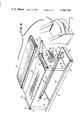
- FIG. 1is a perspective of an exercise machine incorporating a frame assembly and emergency shut-off switch assemblies according to the present invention
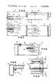
- FIG. 2is a top view of the inventive frame assembly, with the housing assembly removed;
- FIG. 3is a side view of the frame assembly of FIG. 2;
- FIG. 4is a schematic exploded perspective of the inventive frame assembly and a portion of the housing assembly
- FIG. 5is a partial view on line 5--5 of FIG. 2;
- FIG. 6is a partial view on line 6--6 of FIG. 2;
- FIG. 7is a partial view on line 7--7 of FIG. 2;
- FIG. 8is a top view of FIG. 7;
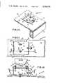
- FIG. 9is a cross-sectional view of a combination shaft and pulley assembly used with the inventive frame assembly
- FIG. 10is a partial perspective of a motor mounting portion of the inventive frame assembly
- FIG. 11is a partial view on line 11--11 of FIG. 12;
- FIG. 12is a partial view on line 12--12 of FIG. 11;
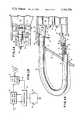
- FIG. 13is a schematic cross section of an upper portion of the housing assembly of the exercise machine of FIG. 1;
- FIG. 14is a top view of a handle mounting assembly of the exercise machine of FIG. 1 incorporating an inventive switch assembly
- FIG. 15is a schematic circuit diagram of the inventive switch assemblies incorporated in an operating circuit of the exercise machine.
- FIG. 1shows an exercise machine 20 having a frame assembly 22 supporting a moving treadmill or endless belt 24 and an upstanding housing assembly 26 releasably connected to the frame assembly 22.
- the belt 24has an elastomer outer surface supported by a no-stretch polyester backing.
- the housing assembly 26is provided with a microprocessor controlled control panel 28, which has a conventional pressure operated on/off switch, speed controls, display dials, and lights, normally found in this type of machine.
- the inventive safety switch system or assemblyemploys two safety handles, 30 and 32.
- These handles, 30 and 32are formed of round pipe or steel tubing and have an arcuate configuration.
- Each of the handleshas an upper end pivotally connected to the housing assembly 26 in such manner that a vertical downward movement of the handle results in movement of a protruding lower portion that actuates a switch of a switch assembly to disconnect power to a motor driving endless belt 24.
- the participant on the exercise machineneed only exert a downward thrust on either or both of the handles, 30 and 32. In this regard, and as may be seen in FIG.
- the handlesare positioned such that not only are the handles easy to grasp and to reach when a person is using the machine, but also the user may simply rest his hands on these handles during the operation of the machine, so that in the event an emergency stop is required, such stop is quickly and simply effected.
- FIGS. 13 and 14the manner of connection of the safety handles 30 and 32 to the housing assembly 26 is illustrated.
- handle 32is connected to the housing assembly 26 in a similar manner.
- an upper portion of housing assembly 26is shaped with an upper opening 34 and a lower opening 36 so that end portions 38 and 40 of the handle 30 are insertable into the interior of the housing assembly.
- the safety handle 30is formed from a tubular member having a hollow upper end portion connected to an upper portion 42 of a mounting bracket 44.
- the mounting bracket 44is connected by a plurality of bolts 46 to reinforcing ribs 48 forming part of the housing assembly 26.
- the upper portion 42 of the mounting bracket 44includes spaced apart plates 50 that pivotally support a cylindrically shaped base 52 of a holding member, generally designated 54.
- a shaft 56protrudes from the base 52.
- the upper end portion 38 of handle 30has openings formed therein alignable with corresponding openings in the shaft 56 for receiving a hitch pin 58 that releasably interconncts the holding member 54 and end portion 38.
- the holding member 54provides a pivotable interconnection between the handle 30 and the mounting bracket 44.
- a threaded shaft 60has an inner end portion 62 fixedly connected to the interior of the lower end portion 40 of handle 30.
- An outer end portion 64 of the shaftpasses through an aperture formed in a mounting flange portion 66 of the mounting bracket 44.
- a nut 68is threadedly engaged with the outer end portion 64 to adjustably interconnect the shaft 60 to the mounting bracket 44.
- a spring 70is positioned between the lower end portion 40 of the safety handle 30 and the mounting flange 66 to bias the handle away from the mounting flange.
- a switch mounting plate 72is connected by a bolt-and-nut connection 74 to a portion of the mounting bracket 44 in such manner that a switch assembly having a switch 76 carried by the mounting plate is positioned with an actuating member 78 adjacent to or in contact with the outer end of shaft 60.
- the shaft 60moves the actuating member 78 to move the switch 76 from a normally open to a closed position.
- a spring 70is used having a spring constant of 200 pounds per inch.
- actuating forcecan vary from a few pounds to as high as 70 pounds, or greater.
- the exercise apparatusis connectable to a conventional alternating-current electric power source.
- the alternating currentis furnished to a power supply circuit board 80 fed through a SCR speed control 82 that converts the alternating current into direct current fed to a D.C. motor 84.
- a microprocessor 86controls both the power supply circuit board 80 and speed control 82.
- the microprocessor 86is positioned in the housing assembly 26 behind the control panel 28.
- the microprocessoris controlled by sensory-touch control buttons and includes a digital readout display.
- Suitable buttonsinclude an on/off control that is pressed and released to turn the machine on and to light up the readout display. Subsequent pressing and releasing of the button turns the display panel and motor off.
- the digital readoutdisplays alternately, at intervals of approximately six seconds, functions such as, heart rate, speed, distance, and time. Speed is calculated to the nearest 0.1 mile per hour and is displayed from about 1.0 to 8.0 mph. Speeds less than 1.0 mph are displayed with a zero. Distance display is to the nearest 0.01 mile and shows accumulated distance up to 9.99 miles. The time indicator works like a stop watch and keeps time to the nearest 0.1 minute.
- the maximum readoutis 99.9 minutes.
- Heart rateis only displayed when heart rate belt is used.
- Speed controlis provided by separate speed increase and speed decrease buttons. Speed is increased or decreased depending upon which button is depressed.
- a hold control buttonis provided so that the display continuously monitors a selected one of the information modes (speed, distance, heart rate, or time).
- a reset controlis provided to automatically reset the distance and time readings to 0.0 for monitoring distance and time sequences.
- pressureis applied to the on-off button on the control panel 28 to turn the apparatus on and light up the display panel.
- Pressure on the speed increase buttontransmits a signal over a line 88 to the speed control 82 so that the motor 84 is energized to start movement of the belt 24.
- the belt speedcontinues to increase as long as pressure is applied to the speed increase button. until a maximum speed, such as, 8 mph, is reached, In a similar manner, the speed of the belt is gradually decreased by pressure on the speed decrease button. Subsequent pressure on the on-off switch of the microprocessor 86 turns the motor off and the belt gradually stops.
- the apparatuscan be immediately shut-off and the belt stopped by grasping handle 30 to close switch 76, or by grasping handle 32 to actuate a switch, designated 76', similar to switch 76. Actuation or closing of either or both the switch 76 and the switch 76' results in immediate stopping of the motor 84.
- a slight delayfor instance, of approximately two or three seconds, before the motor stops.
- a circuit breaker(not shown) is positioned between the power source and the power supply circuit board 80.
- the circuit breakeris accessible from the exterior of the housing assembly 26 to enable switching off the apparatus when not in use to prevent unauthorized users from simply turning the apparatus on by pressure on the on-off switch. Also, since the microprocessor 86 is continually on, even when the on-off switch is not closed, opening of the circuit breaker switch will shut off the microprocessor.
- the frame assembly 22is comprised of a first frame or tubular member 96, a second frame or tubular member 92 parallel to and spaced from the member 96, an end tubular member 98, a third tubular member 100 aligned with the second tubular member 92, and a plate member 94 interconnecting confronting ends of tubular members 92 and 100.
- the plate member 94which is generally U-shaped, has flanges welded to confronting ends of the second and third tubular members.
- a spacer bar 102interconnects portions of the members 92 and 96 to each other.
- a motor mounting plate 104is welded to upper surfaces of the tubular members 96, 98 and 100.
- a safety plate 106is connected to an edge of the plate 104 to close a gap between the mounting plate and the endless belt 24.
- Angle bars 108, 110are welded to confronting inner surfaces of the tubular members 96, 92, respectively.
- the angle barssupport a slider bed 112, preferably formed of a silicone impregnated hardwood. Through bores are formed in the bed and angle bars so that the bed is connected to the frame by lock washers and nuts secured to threaded bolts.
- U-shaped holding brackets 114 and 116are welded to confronting portions of the members 92 and 96 rearwardly of ends of the angle bars 108, 110. These brackets are used to adjustably interconnect the ends 118, 120 of a shaft or axle 122 supporting an idler pulley 124. As illustrated in FIG. 9, end portions of the shaft 122 support bearing races 126 that, in turn, support the pulley 124 for rotation about the shaft 122. Each of the end portions 118, 120 of the shaft 122 has a threaded through bore formed therein for receiving a threaded bolt 128. As illustrated in FIG.
- the head of the boltis maintained in contact with the base of the holding bracket (116 or 114), while the shaft of the bolt is engaged with the bore in the end of the shaft to interconnect the shaft 122 with the frame assembly 22.
- the end of the pulleyis moved toward the head of the bolt.
- pulley adjustment lines 130are located on appropriate portions of the frame assembly.
- a driven pulley 132 mounted on a shaft or axle 134 similar to axle 122is connected to the frame assembly 22 between the slider bed and motor mounting plate 104.
- a U-shaped holding bracket 136is welded to an inner surface of member 96 for adjustably holding an end 138 of the axle 134.
- rotation of a threaded bolt 140 received in a threaded bore formed in the end 138results in changing the angular orientation of the axle 134 with respect to the frame assembly 22.
- the other end 142 of the axle 134has a shape complimentary to the shape of an opening 144 formed in plate member 94.
- each of the pulleys 124 and 132has a central portion B and outer portions A and C that are downwardly tapering from the central portion B to the outer edges of the pulleys.
- the angle of taperis represented, slightly enlarged, by the angle alpha (a) in FIG. 9. Design of the pulleys in this manner results in self centering of the belt 24 on the pulleys, once the orientation of the axles 122 and 134 has been appropriately adjusted parallel by turning of the bolts 128.
- the driven pulley 132includes an enlarged end portion 150 that forms a gear wheel connectable to a drive timing pulley 152 by a drive timing belt 154. As previously described, end 138 of pulley 132 is translatable with respect to frame member 96 to insure proper alignment of end portion 150 with the pulley 152.
- Flanges 154extend downwardly from motor 84 for connecting the motor to a motor mounting plate 156.
- the mounting plate 156is connected by bolt-and-nut connections 158 to an upper surface of a motor base 160.
- the mounting plate 156has longitudinally-extending openings 162 formed therein so that the mounting plate is translatable with respect to the motor base 160.
- the motor base 160has a top surface 164 having openings formed therein to allow passage of the bolt-and-nut connections 158 and a bottom surface 166 having longitudinally-extending openings 168 similar to the openings 162 formed in the motor mounting plate 158.
- Bolt-and-nut connections 169have shafts passing through the openings 168 and an opening formed in the mounting plate 104 for adjustably interconnecting the motor base 160 to the mounting plate 104.
- the top and bottom surfacesare interconnected by a front plate 170 and a rear plate 172.
- An openingis formed in the front plate 170 for the passage of a threaded shaft of a bolt 176.
- a nut 178is welded to an inner surface of plate 170 for threadedly engaging the shaft of bolt 176.
- An upstanding plate 180is welded to an upper surface of the mounting plate 104 and has an opening formed therein for passage of the shaft of bolt 176. After the bolt-and-nut connections 169 have been loosened, turning of bolt 176 results in translation of the base 160 to thereby adjust tension in the belt 154. During such movement, side edges of the bottom of the motor base are guided by parallel strips or bars 182 welded to an upper surface of mounting plate 104.
- the motor base 160is positioned on the mounting plate 104 and rotated to insure proper alignment between pulley 152 and end portion 150 of the driven pulley 132. Once such proper alignment has been obtained, the plates 182 are welded to the plate 104 to maintain the desired orientation.
- the inventive frame assemblymakes it possible to both maintain proper drive belt tension and proper orientation between the driving pulley 152 and driven pulley 150.
- the inventive frame assembly 22provides several advantages. For instance, if it is desired to lubricate the slider bed 112 after extended use of the exercise machine, such lubrication is easily accomplished. First, bolts 128 are rotated to move the idler pulley 124 towards the driven pulley 132 thereby removing tension from belt 24. Belt 24 is then raised and an appropriate lubricant, such as a silicone spray, is applied to the slider bed 112. Bolts 128 are then rotated to position the idler pulley 124 in rough alignment with the pulley adjust lines 130. Power is then furnished to motor 84 to start rotation of belt 24. If the belt starts to move towards one end of idler pulley 124, one of the bolts 128 is rotated to appropriately center the belt.
- an appropriate lubricantsuch as a silicone spray
- bolts 128are rotated out of the bores in the ends 118 and 120 of the axle 122.
- End 138 of the driven pulley 132can then be removed from the holding bracket 136.
- end 142 of the axleis removed from the opening 144 in frame member 94.
- the slider bed 112is separated from the angle bars 108 and 110.
- the belt 24is then removed from the pulleys and bed and replaced with a new belt. Reassembly of the machine takes place in reverse order.
Landscapes
- Health & Medical Sciences (AREA)
- Cardiology (AREA)
- Vascular Medicine (AREA)
- General Health & Medical Sciences (AREA)
- Physical Education & Sports Medicine (AREA)
- Rehabilitation Tools (AREA)
Abstract
Description
Claims (4)
Priority Applications (1)
| Application Number | Priority Date | Filing Date | Title |
|---|---|---|---|
| US06/198,653US4364556A (en) | 1980-10-20 | 1980-10-20 | Emergency shut-off switch and frame assemblies for exercise apparatus |
Applications Claiming Priority (1)
| Application Number | Priority Date | Filing Date | Title |
|---|---|---|---|
| US06/198,653US4364556A (en) | 1980-10-20 | 1980-10-20 | Emergency shut-off switch and frame assemblies for exercise apparatus |
Publications (1)
| Publication Number | Publication Date |
|---|---|
| US4364556Atrue US4364556A (en) | 1982-12-21 |
Family
ID=22734245
Family Applications (1)
| Application Number | Title | Priority Date | Filing Date |
|---|---|---|---|
| US06/198,653Expired - LifetimeUS4364556A (en) | 1980-10-20 | 1980-10-20 | Emergency shut-off switch and frame assemblies for exercise apparatus |
Country Status (1)
| Country | Link |
|---|---|
| US (1) | US4364556A (en) |
Cited By (33)
| Publication number | Priority date | Publication date | Assignee | Title |
|---|---|---|---|---|
| US4445683A (en)* | 1980-08-05 | 1984-05-01 | Ralph Ogden | Exercise treadmill with rockable feet |
| US4602779A (en)* | 1980-08-05 | 1986-07-29 | Ajax Enterprises Corporation | Exercise treadmill |
| US4643418A (en)* | 1985-03-04 | 1987-02-17 | Battle Creek Equipment Company | Exercise treadmill |
| US4708337A (en)* | 1985-12-20 | 1987-11-24 | Industrial Technology Research Institute | Automatic treadmill |
| US4861021A (en)* | 1987-11-18 | 1989-08-29 | Safe/Stress, Inc. | Safety harness on/off switch assembly for treadmills |
| EP0403924A3 (en)* | 1989-06-19 | 1991-10-16 | Life Fitness | Exercise treadmill |
| US5085426A (en)* | 1990-07-30 | 1992-02-04 | Precor Incorporated | Integrated drive and elevation system for exercise apparatus |
| US5163885A (en)* | 1990-07-30 | 1992-11-17 | Precor Incorporated | Integrated drive and elevation system for exercise apparatus |
| US5290205A (en)* | 1991-11-08 | 1994-03-01 | Quinton Instrument Company | D.C. treadmill speed change motor controller system |
| US5441468A (en)* | 1994-03-04 | 1995-08-15 | Quinton Instrument Company | Resiliently mounted treadmill deck |
| US5484362A (en)* | 1989-06-19 | 1996-01-16 | Life Fitness | Exercise treadmill |
| US5707319A (en)* | 1996-08-21 | 1998-01-13 | Riley; Ronald J. | Treadmill adaptive speed control |
| US5944635A (en)* | 1998-01-28 | 1999-08-31 | Digital Concepts Of Missouri, Inc. | Safety shutdown and latch off |
| US6087792A (en)* | 1999-04-21 | 2000-07-11 | Wang; Leao | Control circuit for motor of electric jogging device |
| EP1086721A3 (en)* | 1999-09-07 | 2001-06-13 | Brunswick Corporation | Treadmill mechanism |
| US6436008B1 (en) | 1989-06-19 | 2002-08-20 | Brunswick Corporation | Exercise treadmill |
| US20040023757A1 (en)* | 2002-07-30 | 2004-02-05 | Keys Fitness Products, Inc. | Roller assembly apparatus and method of use |
| US7045732B1 (en)* | 2004-11-26 | 2006-05-16 | Highly Electric Co., Ltd. | Pull retainer emergency safety switch |
| US20060160667A1 (en)* | 1999-09-07 | 2006-07-20 | Brunswick Corporation | Treadmill control system |
| USD527060S1 (en) | 2004-03-22 | 2006-08-22 | Nautilus, Inc. | Exercise device with treadles |
| US7097593B2 (en) | 2003-08-11 | 2006-08-29 | Nautilus, Inc. | Combination of treadmill and stair climbing machine |
| USD546909S1 (en) | 2004-08-16 | 2007-07-17 | Nautilus, Inc. | Treadmill upright |
| US7367926B2 (en) | 2005-08-01 | 2008-05-06 | Fitness Quest Inc. | Exercise treadmill |
| US7455626B2 (en) | 2001-12-31 | 2008-11-25 | Nautilus, Inc. | Treadmill |
| US7618346B2 (en) | 2003-02-28 | 2009-11-17 | Nautilus, Inc. | System and method for controlling an exercise apparatus |
| US8012073B2 (en) | 2009-12-22 | 2011-09-06 | Michael Charles Barnett | Fitness machine with automated variable resistance |
| USRE42698E1 (en) | 2001-07-25 | 2011-09-13 | Nautilus, Inc. | Treadmill having dual treads for stepping exercises |
| US8360936B2 (en) | 2009-05-18 | 2013-01-29 | Adidas Ag | Portable fitness monitoring systems with displays and applications thereof |
| US20130190140A1 (en)* | 2012-01-20 | 2013-07-25 | James Chen | Anti-drift mechanism for treadmill |
| US8694136B2 (en) | 2001-02-20 | 2014-04-08 | Adidas Ag | Performance monitoring devices and methods |
| US8702430B2 (en)* | 2007-08-17 | 2014-04-22 | Adidas International Marketing B.V. | Sports electronic training system, and applications thereof |
| US9615785B2 (en) | 2009-04-01 | 2017-04-11 | Adidas Ag | Method and apparatus to determine the overall fitness of a test subject |
| JP2017144029A (en)* | 2016-02-17 | 2017-08-24 | アルインコ株式会社 | Walking exercise machine |
Citations (17)
| Publication number | Priority date | Publication date | Assignee | Title |
|---|---|---|---|---|
| US921755A (en)* | 1908-09-09 | 1909-05-18 | Thomas Volk | Mechanical training-machine. |
| US937795A (en)* | 1908-05-02 | 1909-10-26 | Leslie S Hackney | Exercising-machine. |
| US1231056A (en)* | 1916-12-18 | 1917-06-26 | Charles S Palmer | Electric iron. |
| US1589977A (en)* | 1923-10-15 | 1926-06-22 | Lucas Andrew | Electrode-holder cut-out for welding tools |
| US2370420A (en)* | 1943-02-10 | 1945-02-27 | Western Electric Co | Electrolytic apparatus |
| US2399915A (en)* | 1945-11-13 | 1946-05-07 | Ward A Drake | Exercising apparatus |
| CH256218A (en)* | 1946-01-04 | 1948-08-15 | Asea Ab | Electric iron. |
| DE1114558B (en)* | 1960-04-02 | 1961-10-05 | Pfisterer Elektrotech Karl | Earthing device for clamping to objects to be earthed, in particular to electrical overhead lines, in high-voltage and high-voltage systems |
| US3332683A (en)* | 1965-03-18 | 1967-07-25 | Jimmy J Rand | Physical conditioning treadmill apparatus |
| US3518985A (en)* | 1968-02-15 | 1970-07-07 | Wayne E Quinton | Control system for an exercise machine using patient's heart rate and heart rate acceleration |
| US3643943A (en)* | 1969-07-28 | 1972-02-22 | Curtis L Erwin Jr | Exerciser with work-indicating mechanism |
| US3659845A (en)* | 1970-04-10 | 1972-05-02 | Quinton Instr | Exercise treadmill and belt support apparatus |
| US3711812A (en)* | 1971-11-29 | 1973-01-16 | Del Mar Eng Lab | Drive and control system for diagnostic and therapeutic exercise treadmill |
| US3731917A (en)* | 1971-02-25 | 1973-05-08 | Townsend Engineering Co | Treadmill exercising device |
| US3737163A (en)* | 1970-08-17 | 1973-06-05 | D Sumrall | Treadmill exercising machine |
| US4192982A (en)* | 1977-08-13 | 1980-03-11 | Metabowerke Gmbh & Co. | Deadman's switch |
| US4270032A (en)* | 1979-04-02 | 1981-05-26 | Deere & Company | Combined safety lever and ignition interlock switch |
- 1980
- 1980-10-20USUS06/198,653patent/US4364556A/ennot_activeExpired - Lifetime
Patent Citations (17)
| Publication number | Priority date | Publication date | Assignee | Title |
|---|---|---|---|---|
| US937795A (en)* | 1908-05-02 | 1909-10-26 | Leslie S Hackney | Exercising-machine. |
| US921755A (en)* | 1908-09-09 | 1909-05-18 | Thomas Volk | Mechanical training-machine. |
| US1231056A (en)* | 1916-12-18 | 1917-06-26 | Charles S Palmer | Electric iron. |
| US1589977A (en)* | 1923-10-15 | 1926-06-22 | Lucas Andrew | Electrode-holder cut-out for welding tools |
| US2370420A (en)* | 1943-02-10 | 1945-02-27 | Western Electric Co | Electrolytic apparatus |
| US2399915A (en)* | 1945-11-13 | 1946-05-07 | Ward A Drake | Exercising apparatus |
| CH256218A (en)* | 1946-01-04 | 1948-08-15 | Asea Ab | Electric iron. |
| DE1114558B (en)* | 1960-04-02 | 1961-10-05 | Pfisterer Elektrotech Karl | Earthing device for clamping to objects to be earthed, in particular to electrical overhead lines, in high-voltage and high-voltage systems |
| US3332683A (en)* | 1965-03-18 | 1967-07-25 | Jimmy J Rand | Physical conditioning treadmill apparatus |
| US3518985A (en)* | 1968-02-15 | 1970-07-07 | Wayne E Quinton | Control system for an exercise machine using patient's heart rate and heart rate acceleration |
| US3643943A (en)* | 1969-07-28 | 1972-02-22 | Curtis L Erwin Jr | Exerciser with work-indicating mechanism |
| US3659845A (en)* | 1970-04-10 | 1972-05-02 | Quinton Instr | Exercise treadmill and belt support apparatus |
| US3737163A (en)* | 1970-08-17 | 1973-06-05 | D Sumrall | Treadmill exercising machine |
| US3731917A (en)* | 1971-02-25 | 1973-05-08 | Townsend Engineering Co | Treadmill exercising device |
| US3711812A (en)* | 1971-11-29 | 1973-01-16 | Del Mar Eng Lab | Drive and control system for diagnostic and therapeutic exercise treadmill |
| US4192982A (en)* | 1977-08-13 | 1980-03-11 | Metabowerke Gmbh & Co. | Deadman's switch |
| US4270032A (en)* | 1979-04-02 | 1981-05-26 | Deere & Company | Combined safety lever and ignition interlock switch |
Cited By (65)
| Publication number | Priority date | Publication date | Assignee | Title |
|---|---|---|---|---|
| US4602779A (en)* | 1980-08-05 | 1986-07-29 | Ajax Enterprises Corporation | Exercise treadmill |
| US4445683A (en)* | 1980-08-05 | 1984-05-01 | Ralph Ogden | Exercise treadmill with rockable feet |
| US4643418A (en)* | 1985-03-04 | 1987-02-17 | Battle Creek Equipment Company | Exercise treadmill |
| US4708337A (en)* | 1985-12-20 | 1987-11-24 | Industrial Technology Research Institute | Automatic treadmill |
| US4861021A (en)* | 1987-11-18 | 1989-08-29 | Safe/Stress, Inc. | Safety harness on/off switch assembly for treadmills |
| US5599259A (en)* | 1989-06-19 | 1997-02-04 | Life Fitness | Exercise treadmill |
| EP0403924A3 (en)* | 1989-06-19 | 1991-10-16 | Life Fitness | Exercise treadmill |
| US6923746B1 (en) | 1989-06-19 | 2005-08-02 | Brunswick Corporation | Exercise treadmill |
| US6436008B1 (en) | 1989-06-19 | 2002-08-20 | Brunswick Corporation | Exercise treadmill |
| US6095951A (en)* | 1989-06-19 | 2000-08-01 | Brunswick Corporation | Exercise treadmill |
| US5484362A (en)* | 1989-06-19 | 1996-01-16 | Life Fitness | Exercise treadmill |
| US5752897A (en)* | 1989-06-19 | 1998-05-19 | Brunswick Corporation | Exercise treadmill |
| US5085426A (en)* | 1990-07-30 | 1992-02-04 | Precor Incorporated | Integrated drive and elevation system for exercise apparatus |
| US5163885A (en)* | 1990-07-30 | 1992-11-17 | Precor Incorporated | Integrated drive and elevation system for exercise apparatus |
| US5545112A (en)* | 1991-11-08 | 1996-08-13 | Quinton Instrument Company | D.C. treadmill speed change motor controller system |
| US5489250A (en)* | 1991-11-08 | 1996-02-06 | Quinton Instrument Company | Treadmill deceleration system and method |
| US5290205A (en)* | 1991-11-08 | 1994-03-01 | Quinton Instrument Company | D.C. treadmill speed change motor controller system |
| US5441468A (en)* | 1994-03-04 | 1995-08-15 | Quinton Instrument Company | Resiliently mounted treadmill deck |
| US5707319A (en)* | 1996-08-21 | 1998-01-13 | Riley; Ronald J. | Treadmill adaptive speed control |
| US5944635A (en)* | 1998-01-28 | 1999-08-31 | Digital Concepts Of Missouri, Inc. | Safety shutdown and latch off |
| US6087792A (en)* | 1999-04-21 | 2000-07-11 | Wang; Leao | Control circuit for motor of electric jogging device |
| EP1086721A3 (en)* | 1999-09-07 | 2001-06-13 | Brunswick Corporation | Treadmill mechanism |
| US6776740B1 (en) | 1999-09-07 | 2004-08-17 | Brunswick Corporation | Treadmill mechanism |
| US20060160667A1 (en)* | 1999-09-07 | 2006-07-20 | Brunswick Corporation | Treadmill control system |
| US9589480B2 (en) | 2001-02-20 | 2017-03-07 | Adidas Ag | Health monitoring systems and methods |
| US9767709B2 (en) | 2001-02-20 | 2017-09-19 | Adidas Ag | Performance monitoring systems and methods |
| US11557388B2 (en) | 2001-02-20 | 2023-01-17 | Adidas Ag | Performance monitoring systems and methods |
| US10991459B2 (en) | 2001-02-20 | 2021-04-27 | Adidas Ag | Performance monitoring systems and methods |
| US10943688B2 (en) | 2001-02-20 | 2021-03-09 | Adidas Ag | Performance monitoring systems and methods |
| US10082396B2 (en) | 2001-02-20 | 2018-09-25 | Adidas Ag | Performance monitoring systems and methods |
| US10060745B2 (en) | 2001-02-20 | 2018-08-28 | Adidas Ag | Performance monitoring systems and methods |
| US9983007B2 (en) | 2001-02-20 | 2018-05-29 | Adidas Ag | Performance monitoring systems and methods |
| US9711062B2 (en) | 2001-02-20 | 2017-07-18 | Adidas Ag | Performance monitoring systems and methods |
| US9683847B2 (en) | 2001-02-20 | 2017-06-20 | Adidas Ag | Performance monitoring systems and methods |
| US9679494B2 (en) | 2001-02-20 | 2017-06-13 | Adidas Ag | Performance monitoring systems and methods |
| US9489863B2 (en) | 2001-02-20 | 2016-11-08 | Adidas Ag | Performance monitoring systems and methods |
| US9478149B2 (en) | 2001-02-20 | 2016-10-25 | Adidas Ag | Performance monitoring systems and methods |
| US9415267B2 (en) | 2001-02-20 | 2016-08-16 | Adidas Ag | Performance monitoring systems and methods |
| US9401098B2 (en) | 2001-02-20 | 2016-07-26 | Adidas Ag | Performance monitoring systems and methods |
| US8694136B2 (en) | 2001-02-20 | 2014-04-08 | Adidas Ag | Performance monitoring devices and methods |
| USRE42698E1 (en) | 2001-07-25 | 2011-09-13 | Nautilus, Inc. | Treadmill having dual treads for stepping exercises |
| US7544153B2 (en) | 2001-12-31 | 2009-06-09 | Nautilus, Inc. | Treadmill |
| US7455626B2 (en) | 2001-12-31 | 2008-11-25 | Nautilus, Inc. | Treadmill |
| US20040023757A1 (en)* | 2002-07-30 | 2004-02-05 | Keys Fitness Products, Inc. | Roller assembly apparatus and method of use |
| US6860838B2 (en)* | 2002-07-30 | 2005-03-01 | Keys Fitness Products, Inc. | Roller assembly apparatus and method of use |
| US7618346B2 (en) | 2003-02-28 | 2009-11-17 | Nautilus, Inc. | System and method for controlling an exercise apparatus |
| US7967730B2 (en) | 2003-02-28 | 2011-06-28 | Nautilus, Inc. | System and method for controlling an exercise apparatus |
| US7097593B2 (en) | 2003-08-11 | 2006-08-29 | Nautilus, Inc. | Combination of treadmill and stair climbing machine |
| USD527060S1 (en) | 2004-03-22 | 2006-08-22 | Nautilus, Inc. | Exercise device with treadles |
| USD546909S1 (en) | 2004-08-16 | 2007-07-17 | Nautilus, Inc. | Treadmill upright |
| US7045732B1 (en)* | 2004-11-26 | 2006-05-16 | Highly Electric Co., Ltd. | Pull retainer emergency safety switch |
| US20060113174A1 (en)* | 2004-11-26 | 2006-06-01 | Hsu C P | Pull retainer emergency safety switch |
| US7367926B2 (en) | 2005-08-01 | 2008-05-06 | Fitness Quest Inc. | Exercise treadmill |
| US10062297B2 (en) | 2007-08-17 | 2018-08-28 | Adidas International Marketing B.V. | Sports electronic training system, and applications thereof |
| US8702430B2 (en)* | 2007-08-17 | 2014-04-22 | Adidas International Marketing B.V. | Sports electronic training system, and applications thereof |
| US12020588B2 (en) | 2007-08-17 | 2024-06-25 | Adidas International Marketing B.V. | Sports electronic training system, and applications thereof |
| US9615785B2 (en) | 2009-04-01 | 2017-04-11 | Adidas Ag | Method and apparatus to determine the overall fitness of a test subject |
| US9908001B2 (en) | 2009-05-18 | 2018-03-06 | Adidas Ag | Portable fitness monitoring systems with displays and applications thereof |
| US9550090B2 (en) | 2009-05-18 | 2017-01-24 | addidas AG | Portable fitness monitoring systems with displays and applications thereof |
| US8360936B2 (en) | 2009-05-18 | 2013-01-29 | Adidas Ag | Portable fitness monitoring systems with displays and applications thereof |
| US8801577B2 (en) | 2009-05-18 | 2014-08-12 | Adidas Ag | Portable fitness monitoring systems with displays and applications thereof |
| US8012073B2 (en) | 2009-12-22 | 2011-09-06 | Michael Charles Barnett | Fitness machine with automated variable resistance |
| US20130190140A1 (en)* | 2012-01-20 | 2013-07-25 | James Chen | Anti-drift mechanism for treadmill |
| US8951167B2 (en)* | 2012-01-20 | 2015-02-10 | Joong Chenn Industry Co., Ltd. | Anti-drift mechanism for treadmill |
| JP2017144029A (en)* | 2016-02-17 | 2017-08-24 | アルインコ株式会社 | Walking exercise machine |
Similar Documents
| Publication | Publication Date | Title |
|---|---|---|
| US4364556A (en) | Emergency shut-off switch and frame assemblies for exercise apparatus | |
| US5062632A (en) | User programmable exercise machine | |
| US5256117A (en) | Stairclimbing and upper body, exercise apparatus | |
| USRE34959E (en) | Stair-climbing exercise apparatus | |
| CA2696163C (en) | Dual direction exercise treadmill with moment arm resistance | |
| US4659077A (en) | Exercise device | |
| US6846272B2 (en) | Elliptical step exercise apparatus | |
| US4643418A (en) | Exercise treadmill | |
| US5033736A (en) | Passive exercise bicycle | |
| US4502679A (en) | Motorized variable speed treadmill | |
| US4676501A (en) | Exercise machine | |
| US6220991B1 (en) | Motorized exercise bike | |
| US7338417B2 (en) | Perineum muscular power increase device and a method thereof | |
| US3989240A (en) | Electrically timed exercising device | |
| WO1989004696A1 (en) | Stair climbing exercise apparatus | |
| US5419752A (en) | Muscle exercise apparatus for the physically disabled | |
| US4426075A (en) | Emergency shut-off switch for exercise apparatus | |
| US20030045402A1 (en) | Exercise device | |
| CN106693299A (en) | Leg strength leg swing exercise trainer | |
| CH673587A5 (en) | ||
| JPH01107779A (en) | rowing machine | |
| DE2117531A1 (en) | Device for therapeutic gymnastics, athletic training and physical culture | |
| WO1999052601A1 (en) | Pushing/pulling exerciser | |
| CN111840898B (en) | Manpower running machine capable of setting movement speed | |
| JP2009517173A (en) | Exercise treadmill for towing and tensioning |
Legal Events
| Date | Code | Title | Description |
|---|---|---|---|
| AS | Assignment | Owner name:AMERICAN TREDEX CORPORATION, 1450 WABASH AVE., TE Free format text:ASSIGNMENT OF ASSIGNORS INTEREST.;ASSIGNOR:OTTE GARY;REEL/FRAME:003863/0335 Effective date:19800917 | |
| AS | Assignment | Owner name:NISSEN CORPORATION, 930 27TH AVE., S.W. CEDAR RAPI Free format text:ASSIGNMENT OF ASSIGNORS INTEREST.;ASSIGNOR:AMERICAN TREDEX CORPORATION, A CORP. OF IN.;REEL/FRAME:003944/0071 Effective date:19811221 | |
| STCF | Information on status: patent grant | Free format text:PATENTED CASE | |
| AS | Assignment | Owner name:UNIVERSAL GYM EQUIPMENT, INC., 930 27TH AVENUE, S. Free format text:ASSIGNMENT OF ASSIGNORS INTEREST. AS OF AUG. 1, 1981.;ASSIGNOR:NISSEN CORPORATION, A CORP OF IO.;REEL/FRAME:004489/0622 Effective date:19851118 | |
| AS | Assignment | Owner name:FF ACQUISITION CORP., MISSISSIPPI Free format text:ASSIGNMENT OF ASSIGNORS INTEREST;ASSIGNOR:CONGRESS FINANCIAL CORPORATION (FLORIDA);REEL/FRAME:009935/0317 Effective date:19980818 | |
| AS | Assignment | Owner name:CONGRESS FINANCIAL CORPORATION (FLORIDA), FLORIDA Free format text:CERTIFICATE OF TITLE;ASSIGNOR:UNIVERSAL GYM EQUIPMENT, INC.;REEL/FRAME:009490/0094 Effective date:19980818 |