US4361375A - Miniature audio connector - Google Patents
Miniature audio connectorDownload PDFInfo
- Publication number
- US4361375A US4361375AUS06/187,287US18728780AUS4361375AUS 4361375 AUS4361375 AUS 4361375AUS 18728780 AUS18728780 AUS 18728780AUS 4361375 AUS4361375 AUS 4361375A
- Authority
- US
- United States
- Prior art keywords
- housing
- members
- connector
- lip
- latch
- Prior art date
- Legal status (The legal status is an assumption and is not a legal conclusion. Google has not performed a legal analysis and makes no representation as to the accuracy of the status listed.)
- Expired - Lifetime
Links
- 230000010287polarizationEffects0.000claimsabstractdescription30
- 230000013011matingEffects0.000claimsabstractdescription6
- 239000004020conductorSubstances0.000claimsdescription11
- 238000000926separation methodMethods0.000claims1
- PXHVJJICTQNCMI-UHFFFAOYSA-NNickelChemical compound[Ni]PXHVJJICTQNCMI-UHFFFAOYSA-N0.000description8
- 125000006850spacer groupChemical group0.000description6
- 210000005069earsAnatomy0.000description5
- 229910000881Cu alloyInorganic materials0.000description4
- 230000006835compressionEffects0.000description3
- 238000007906compressionMethods0.000description3
- 229910052759nickelInorganic materials0.000description3
- 229910000679solderInorganic materials0.000description3
- 238000005476solderingMethods0.000description3
- 229920001971elastomerPolymers0.000description2
- 239000000463materialSubstances0.000description2
- 229910001369BrassInorganic materials0.000description1
- RYGMFSIKBFXOCR-UHFFFAOYSA-NCopperChemical compound[Cu]RYGMFSIKBFXOCR-UHFFFAOYSA-N0.000description1
- 229910000570CupronickelInorganic materials0.000description1
- BQCADISMDOOEFD-UHFFFAOYSA-NSilverChemical compound[Ag]BQCADISMDOOEFD-UHFFFAOYSA-N0.000description1
- 229910000831SteelInorganic materials0.000description1
- 229910045601alloyInorganic materials0.000description1
- 239000000956alloySubstances0.000description1
- 238000005452bendingMethods0.000description1
- DMFGNRRURHSENX-UHFFFAOYSA-Nberyllium copperChemical compound[Be].[Cu]DMFGNRRURHSENX-UHFFFAOYSA-N0.000description1
- 239000010951brassSubstances0.000description1
- ZCDOYSPFYFSLEW-UHFFFAOYSA-Nchromate(2-)Chemical compound[O-][Cr]([O-])(=O)=OZCDOYSPFYFSLEW-UHFFFAOYSA-N0.000description1
- 239000011248coating agentSubstances0.000description1
- 238000000576coating methodMethods0.000description1
- 239000010960cold rolled steelSubstances0.000description1
- 229910052802copperInorganic materials0.000description1
- 239000010949copperSubstances0.000description1
- 230000000881depressing effectEffects0.000description1
- 230000000994depressogenic effectEffects0.000description1
- 238000010438heat treatmentMethods0.000description1
- 238000003780insertionMethods0.000description1
- 230000037431insertionEffects0.000description1
- 238000012986modificationMethods0.000description1
- 230000004048modificationEffects0.000description1
- 239000004033plasticSubstances0.000description1
- 238000007747platingMethods0.000description1
- 229910052709silverInorganic materials0.000description1
- 239000004332silverSubstances0.000description1
- 239000010959steelSubstances0.000description1
- 229920001169thermoplasticPolymers0.000description1
- 229920002725thermoplastic elastomerPolymers0.000description1
- 239000012815thermoplastic materialSubstances0.000description1
- 239000004416thermosoftening plasticSubstances0.000description1
Images


Classifications
- H—ELECTRICITY
- H01—ELECTRIC ELEMENTS
- H01R—ELECTRICALLY-CONDUCTIVE CONNECTIONS; STRUCTURAL ASSOCIATIONS OF A PLURALITY OF MUTUALLY-INSULATED ELECTRICAL CONNECTING ELEMENTS; COUPLING DEVICES; CURRENT COLLECTORS
- H01R13/00—Details of coupling devices of the kinds covered by groups H01R12/70 or H01R24/00 - H01R33/00
- H01R13/62—Means for facilitating engagement or disengagement of coupling parts or for holding them in engagement
- H01R13/639—Additional means for holding or locking coupling parts together, after engagement, e.g. separate keylock, retainer strap
- H01R13/6395—Additional means for holding or locking coupling parts together, after engagement, e.g. separate keylock, retainer strap for wall or panel outlets
- H—ELECTRICITY
- H01—ELECTRIC ELEMENTS
- H01R—ELECTRICALLY-CONDUCTIVE CONNECTIONS; STRUCTURAL ASSOCIATIONS OF A PLURALITY OF MUTUALLY-INSULATED ELECTRICAL CONNECTING ELEMENTS; COUPLING DEVICES; CURRENT COLLECTORS
- H01R13/00—Details of coupling devices of the kinds covered by groups H01R12/70 or H01R24/00 - H01R33/00
- H01R13/62—Means for facilitating engagement or disengagement of coupling parts or for holding them in engagement
- H01R13/627—Snap or like fastening
- H—ELECTRICITY
- H01—ELECTRIC ELEMENTS
- H01R—ELECTRICALLY-CONDUCTIVE CONNECTIONS; STRUCTURAL ASSOCIATIONS OF A PLURALITY OF MUTUALLY-INSULATED ELECTRICAL CONNECTING ELEMENTS; COUPLING DEVICES; CURRENT COLLECTORS
- H01R13/00—Details of coupling devices of the kinds covered by groups H01R12/70 or H01R24/00 - H01R33/00
- H01R13/64—Means for preventing incorrect coupling
Definitions
- the inventionrelates generally to electrical connectors, and more particularly, to such connectors suitable for use in audio systems.
- U.S. Pat. No. 3,219,961issued to the present inventors James R. Bailey et al, Nov. 23, 1965 and assigned to the assignee of the present invention, discloses a prior art electrical connector suitable for use in audio systems.
- Such connectorincludes a pair of detachable members, one member being connected to a source of sound, such as a microphone, and the other being connected, for example, to an audio amplifier.
- One memberprovides a sleeve-like female receptacle for the other member.
- a mechanical release latchis provided to disengage the members as desired.
- the mechanical latching systemcomprises a rigid latch with a separate biasing spring.
- the latchis provided with pivot projections at one end and at the end remote thereto, a finger piece and a detent which engages a notch in the inner walls of one of the pair of detachable members.
- one of the memberssuch as the one containing the plural female pin receptacles, be mounted on a panel or chassis and the male connector assembly having a polarization mating groove be interfitted with the stationary member.
- a separate internally disposed resilient conductive elementis used to bridge the interfitted members when mated. Consequently, while such prior art connector is useful in many applications, when such connector is to be miniaturized in size use of plural components makes assembly difficult. Further, with one of the connector members stationary mounted a new and unique latch release mechanism is desired.
- an audio connectorcomprising the combination of stationary and detachable members, such detachable member being, for example, a male member having a hollow sleeve-like conductive housing including a base-pin insert with a plurality of male conductive contact pins.
- the stationary memberhas an appended escutcheon plate for panel or chassis mounting and a post-like conductive housing member being, for example, a female connector member having a plurality of receptacles adapted to mate with the contact pins.
- the post-like female conductive housingis shaped to interfit in coaxial alignment within the hollow sleeve-like conductive housing member of the male connector.
- a mechanical latching systemincludes a unitary latch, having an elongated resilient tongue-like portion with a pair of offset conductive wing-like members interconnected to a spring-actuated slidably disposed lever of the release mechanism.
- the unitary latchis in electrical contact with a polarization groove formed in a hollow passageway of the sleeve-like male conductive housing having a lip formed within its inner passageway wall with the polarization groove cut through one section of such lip.
- the stationary female receptacle memberis interfitted within the male member with the elongated resilient tongue-like portion of the latch positioned within the polarization groove to mechanically key the orientation and mating of the connector members.
- the tongue-like portion of the latchWhen inserted, the tongue-like portion of the latch passes through the polarization grooves, and the wing-like members engage the lip formed within the hollow conductive sleeve-like housing member of the male connector member to inter-lock the conductors.
- the conductorsare disengaged when the spring-actuated release mechanism mounted on the stationary member is slid to depress the latch and thereby remove the wing-like members from the lip of the housing.
- the tongue-like portion of the latch systemengages the inner walls of polarization groove to provide electrical continuity between the mated stationary and detachable conductive housing members, reduce mechanical vibrations between the mated components and ensure positive latching.
- FIG. 1is an exploded pictorial view of the stationary and detachable member components of the connector according to the invention
- FIG. 2is an exploded pictorial view of the components of the stationary mounted female member of the audio connector shown in FIG. 1;
- FIGS. 2A & 2Bare plan views of the lock ring terminal member in FIGS. 2, 3 and 11 for solder and printed circuit applications, respectively;
- FIG. 3is a detailed cross-sectional view of the assembled stationary connector member components taken along line 3--3 shown in FIG. 1;
- FIG. 4is an exploded pictorial view of the detachable male connector member, shown in FIG. 1;
- FIG. 4Ais an isometric view of a preferred cable clamp with the cable conductor attached
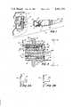
- FIG. 5is detailed cross-sectional view of the post-like conductive housing of the stationary connector member illustrating the mechanical latching system and release mechanism mounted thereon taken along and in the direction of the line and arrows 5--5 in FIG. 6;
- FIG. 5Ais a view similar to FIG. 5 showing the release button slid rearwardly to the right to engage and depress the wing portions of the latch assembly to the disengagement position;
- FIG. 6is a top elevation view of the housing shown in FIG. 5 taken along the line 6--6;
- FIG. 7is a side elevation view of a portion of the latch release mechanism shown in FIGS. 2 and 5;
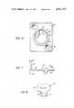
- FIG. 8is a front elevation view of a portion of the latch release mechanism of the stationary connector member shown in FIGS. 1, 3, 5 and 6, taken along the line 8--8 in FIG. 7;
- FIG. 9is an end elevation view of the conductive housing of the detachable male connector member taken along the line 9--9 in FIG. 4;
- FIG. 10is an isometric view of the return spring member connecting the latch release mechanism to the conductive housing shown in FIGS. 2 and 5;
- FIG. 10Ais a side elevational view of the spring member taken along the line 10A--10A in FIG. 10;
- FIG. 11 and FIG. 11Aare end elevation views of the locking ring and ground terminal of the stationary female connector member 12, taken along the line 11--11 in FIG. 2;
- FIG. 12is an end elevation view of the collar and escutcheon plate member taken along the line 12--12 in FIG. 2.
- FIG. 13is a partial cross-sectional and side elevation view of the male and female connector members in the engaged or inter-mated position, together with internal structure also shown in cross section;
- FIG. 13 Ais a view similar to FIG. 13 showing the interfitted male and female connector members, partially detached with the release button lever and latch assembly depressed;
- FIG. 14is a plan view partially broken away to reveal underlying structure of the mated male and female connector members.
- Connector 10includes the combination of a mounted stationary member, such as, for example, female receptacle member 12 and detachable male member 14.
- the mounted stationary connector member 12includes a conductive housing 16, preferrably of a copper alloy with a bright nickel plate, having a hollow post-like section 18 as shown in cross section in FIG. 5.
- Member 12also includes a plug insert 20 having a plurality of conductive female receptacles 22 formed therein, electrically insulated from each other by the dielectric insert base 24. As shown in FIGS.
- the conductive housing 16 with the plug insert 20is disposed within hollow collar member 26 also of a copper alloy and nickel plate. Plate 28 extends laterally from member 26 for panel or chassis mounting by means of screw holes 30 (FIG. 12).
- the latch assembly 36 of the present invention and release mechanism 38 co-operating with the mechanical latch assembly 36are carried by the conductive housing portion 18 of the stationary female member 12.
- Push button 40provides for actuation of the release mechanism 38 to separate the detachable male connector member 14 after interfitting the connector components 12, 14 for electrical continuity.
- the hollow post-like section 18is adapted to fit inside the hollow portion of the detachable male connector member 14 when coaxially aligned therewith.
- the female pin receptacles 22terminate in crimpable end portions 22a which are adapted for connection to signal leads leading to external circuitry such as for example an audio amplifier.
- Notches 44are provided to engage and mate with tabs 46 of an insulating spacer 48, preferably of a molded high strength thermoplastic similar to the material employed for the insert base 24 to ensure positive interlocking of the assembled components 24, 48 and ease of the assembly without any soldering.
- Passageways 50provide for clearance of the ends 22a of the female receptacles 22.
- Flat portion 52 formed on the top of spacer 48abuts with flat portion 54 to define a chamber 53 for receiving the latch assembly 36 (FIG. 3).
- the lock ring 56preferably of a hard brass alloy with electro-tined plating has a solder terminal 58 (FIG. 2A) and printed circuit terminal 58a (FIG. 2B) and ears 60.
- Protrusions 62a of housing 18 extending through passageway 64 in collar member 26are peened or staked over adjacent walls of the lock ring (FIG. 11A) to secure components 16, 20, 48 and 26 at one end.
- End wall 26a (FIG. 12) of member 26abuts lock ring 56 after the lock ring is secured as shown in FIG. 11A.
- At the other end lip 151 in a passageway within housing 18retricts movement of the aforesaid components as shown in FIGS. 3, 5 and 5A.
- the detachable male connector member 14comprises a hollow conductive housing 70, as shown in FIG. 4, preferably of a copper alloy with a bright nickel plate.
- the conductive housing 70has a threaded section 72, hollow passageway and at the other end a polarization groove 74. For the reasons to be hereinafter described such end also includes a lip 76.
- the internal components axially disposed within conductive housing 70include a base-pin insert 78 having a dielectric base 80, preferably of a molded high strength thermoplastic material and a plurality of conductive male contact pins 82, preferably a silver plated copper alloy with a clear chromate coating.
- the pins 82are electrically insulated from each other by dielectric base 80 and protrude through the base 80 so as to provide terminal portions 82a for connection to signal leads 84 of the cable conductor 86.
- a ridge 88engages a lip formed within housing 70 to retain the base within such housing.
- a hollow insulating spacer 90having an axial passageway 92 for the signal leads 84 of the cable conductor 86 follows.
- Such spacer 90is provided with tabs 94 and 96 to engage notches 98, 100, respectively, formed in a polarized space relationship about the periphery of base 80 to ensure positive interlocking of the assembled components and ease of the assembly without any soldering.
- the opposing end of insulating spacer 90includes three circumferentially disposed tabs, here one being invisible, 102 and 104 to frictionally engage the split semi-circular portions 109 of resilient wall 106 of a conductive cable clamp 108. (See FIG. 4A)
- the tabs 102, 104engage the inner walls of the split portions 109 of clamp 108 and are held to it by a press fit.
- the insulating spacer 90has a raised tab 110 for introduction within the slot 112 of split circular walls 109 of clamp 108 and are held to it by a press fit. Cable clamp 108 as shown in FIG.
- 4Afurther comprises rib section 114, rear ears 116 and front ears 118 with the rear ears 116 crimped to the outer cable cover 120, here of rubber or plastic of audio cable 86.
- the front ears 118are crimped to the shielding braid 124, here preferably of copper.
- Plural signal leads 84whose number is determined by the number of contact pins 82, conventionally, three to five, here only three being shown, are electrically connected, for example by solder to end portions 82a of the contact pins 82.
- Nib 126 in rib section 114provides for locking of the cable clamp 108 in a slot 192 formed in the threaded end 72 of housing 70 (FIG. 13) to prevent rotation of the clamp.
- Flared walls 128engage the inner walls of conductive housing 70 to electrically interconnect cable clamp 108 and, thereby, shielding braid 124 to conductive housing 70 (FIG. 13) for electrical continuity.
- Cable clamp 108is preferably fabricated of steel and has an electro-tinned finish.
- connector member 14further includes end cap 130 secured to the threaded non-mating end 72 of housing 70 by means of internal threads 132.
- the end cap 130is preferably of a molded black thermoplastic elastomer.
- Flex relief boot 134preferably of a non-rigid rubber material, is appended to the end of end cap 130.
- the latch assembly 36is a unitary U-shaped, resilient structure having an elongated tongue-like conductive portion 140 and a pair of conductive wing-like members 142, 143, offset from the elongated conductive portion 140, as shown.
- the offset wing-like members 142, 143have raised arcuate portions 144, 145 (FIG. 6) and front edges 146, 147 see also (FIG. 6)
- the elongated portion 140is adapted to pass through polarization groove 74 of member 14 (FIGS. 4, 5, 9, 13, 13A).
- the latch 36includes a bight portion 148 (FIGS. 5, 5A) disposed within notch 150 in housing wall portion 18a and is followed by a raised flattened portion 152.
- Elongated resilient tongue-like portion 154follows with a slightly upturned depressible end portion 156.
- Latch assembly 36is preferably fabricated of beryllium copper and is nickel plated after heat treatment.
- the polarization groove 74is provided within sleeve-like housing 70 to receive and substantially enclose latch assembly 36.
- the polarization groove 74having substantially straight upper and side walls 158, 159 (FIG. 9) provides a receptacle for the elongated tongue-like portion 140 of latch 36 so that it mechanically keys the latch to thereby orient the mating of the contact pins 82 within receptacles 22 (FIGS.
- Polarization groove 74extends substantially throughout half of the length of housing 70.
- the width W 1 of the polarization groove 74is slightly larger than width W 2 of tongue-like portion 154 of latch 36 to receive such portion 154 (FIG. 6).
- the width W 1 of groove 74is smaller than the width W 3 across the pair of wing-like members 142, 143.
- Such members 142, 143in particular, edges 146, 147 of such members engage the lip portion 76 (FIGS. 9, 13) of housing 70 when the connector members 12, 14 are interfitted.
- the raised portion 144, 145 of the wing-like membersengage the walls 76 adjacent the groove 74, also shown in FIGS. 9, 14.
- the lip 76 adjacent the entrance to the hollow passageway 71 in housing 70provides for positive latching of the interfitted housings 16 and 70 (FIGS. 13-14 inclusive).
- the lip 76is contacted by the front edges 146, 147 of the offset wing-like members after insertion of the latch 36 within the polarization groove 74.
- the combination of mechanical forces evolving with the compression of latch end 156 by contact with the upper straight wall 159 (FIG. 9) forming polarization groove 74 and the compression of the wing-like arcuate portions 144, 145 by the housing walls adjacent to the groove 74provide for the vibration-resistant, anti-rattle characteristics of the mated members of the overall miniature audio connector.
- the latch assembly 36is shown provided with an upturned portion 164 of the end of elongated portion 140 and extends within groove 166 in conductive section 18.
- the wing-like portions 143, 144 of the latch assemblyextend within notch 170 and depression of the upturned portion 164 results in the disengagement of the front portions of the wing-like members 143, 144 from the lip portion 76 of the polarizaton groove 74 to provide clearance for the movement of the wing-like members and withdrawal of the detachable connector member 14 from the stationary connector member 12 and the breaking of the audio circuit, FIG. 5A, 13A.
- An elongated slidably disposed release lever 172 of cold rolled steel with a bright nickelplatehas an intermediate substantially V-shaped portion 174 bridging ring-like portions 176, 177 of conductive housing 18 section and an upturned push button 40.
- a return spring 180 of tinned 0.014 music wireengages V-section 174 with an end 184 disposed within groove 166 (FIG. 6) defined between rings 176, 177 and the opening end 182 defining a hook disposed within aperture 188 in body section 18, as shown in FIGS. 5 and 6.
- the V-section 174is formed with an angle of approximately 60 degrees (FIG. 7) with end portion 190 of the elongated lever 172 of the latch release mechanism 38 adapted to be supported on ring wall section 177.
- FIGS. 12, 13, 13A groove 41 in the wall of the collar member 26is defined by top and sidewalls 43, 45, respectively, to provide for disposition of release lever 172.
- the configuration of end wall 26a (FIG. 12)is also shown conforming to end 62 (FIG. 11A) of conductive housing 18.
- Lock ring 56is secured to wall 26a, as by staking wings 62a or soldering (FIG. 11A) The depression of button 40 (FIGS.
- the polarization groove 126is in the stationary member 120 and the latch assembly is provided in the detachable female connector 14.
- the disposition of the polarization groove 74 and latch assembly 36is reversed with the polarization groove now disposed in the detachable member 14 while the latch assembly 36 is disposed in the stationary female receptacle connector member 12.
Landscapes
- Details Of Connecting Devices For Male And Female Coupling (AREA)
Abstract
Description
Claims (8)
Priority Applications (1)
| Application Number | Priority Date | Filing Date | Title |
|---|---|---|---|
| US06/187,287US4361375A (en) | 1980-09-15 | 1980-09-15 | Miniature audio connector |
Applications Claiming Priority (1)
| Application Number | Priority Date | Filing Date | Title |
|---|---|---|---|
| US06/187,287US4361375A (en) | 1980-09-15 | 1980-09-15 | Miniature audio connector |
Publications (1)
| Publication Number | Publication Date |
|---|---|
| US4361375Atrue US4361375A (en) | 1982-11-30 |
Family
ID=22688362
Family Applications (1)
| Application Number | Title | Priority Date | Filing Date |
|---|---|---|---|
| US06/187,287Expired - LifetimeUS4361375A (en) | 1980-09-15 | 1980-09-15 | Miniature audio connector |
Country Status (1)
| Country | Link |
|---|---|
| US (1) | US4361375A (en) |
Cited By (46)
| Publication number | Priority date | Publication date | Assignee | Title |
|---|---|---|---|---|
| US4493525A (en)* | 1983-01-31 | 1985-01-15 | Amp Incorporated | Electrical plug connector and receptacle therefor |
| US4634208A (en)* | 1983-01-31 | 1987-01-06 | Amp Incorporated | Electrical plug connector and method of terminating a cable therewith |
| US4964818A (en)* | 1985-11-22 | 1990-10-23 | Weatherley Richard M | Electrical socket |
| US5288248A (en)* | 1991-10-28 | 1994-02-22 | Foxconn International | Totally shielded DIN connector |
| EP0594937A1 (en)* | 1992-10-30 | 1994-05-04 | Contact GmbH Elektrische Bauelemente | Electric plug connection |
| WO1999022426A1 (en)* | 1997-10-24 | 1999-05-06 | David Haut | Flush/recessable junction device |
| US6086390A (en)* | 1997-10-24 | 2000-07-11 | Haut; David | Flush/recessable junction device |
| US6186819B1 (en) | 1999-01-27 | 2001-02-13 | Cardell Corporation | Latching mechanism for a connector |
| US6261129B1 (en)* | 1999-01-18 | 2001-07-17 | Sony Corporation | Connector device having an erroneous fitting preventing portion |
| US6312277B1 (en) | 1999-01-27 | 2001-11-06 | Cardell Corporation | Connector position assurance device for a connector |
| US20040185710A1 (en)* | 2003-03-19 | 2004-09-23 | Thomas Gregory D | Multi-stack desktop computer/set-top box audio connector |
| US20060084298A1 (en)* | 2004-10-20 | 2006-04-20 | Kabushiki Kaisha Audio-Technica | Condenser microphone |
| US20080207057A1 (en)* | 2006-04-07 | 2008-08-28 | Kabushiki Kaisha Audio-Technica | Microphone connector and method of shielding the same |
| US20080212275A1 (en)* | 2007-03-02 | 2008-09-04 | James Waryck | Quick connect/disconnect cable apparatus for computer peripherals |
| US20090046981A1 (en)* | 2007-08-13 | 2009-02-19 | Illum Technologies, Inc. | High density fiber optic interconnect system with push-release mechanism and method for using same |
| US20090191738A1 (en)* | 2008-01-25 | 2009-07-30 | Michael Aaron Kadar-Kallen | Connector Assembly Having A Movable Plug |
| US20090269981A1 (en)* | 2008-04-25 | 2009-10-29 | Omron Corporation | Connector |
| US20090291585A1 (en)* | 2008-05-22 | 2009-11-26 | Hautlet, Llc | Flush/recessable junction device |
| WO2010141860A1 (en)* | 2009-06-04 | 2010-12-09 | Purdue Research Foundation | Magnetic field system and method for mitigating passive intermodulation distortion |
| WO2011156653A1 (en)* | 2010-06-09 | 2011-12-15 | Zenith Investments Llc | Flexible trs connector |
| US20120034807A1 (en)* | 2010-08-04 | 2012-02-09 | Powertech Industrial Co., Ltd. | Detachment-preventing plug |
| US20130056259A1 (en)* | 2011-09-07 | 2013-03-07 | Dish Network L.L.C. | In-wall extension apparatus |
| US8461465B2 (en) | 2010-05-28 | 2013-06-11 | Apple Inc. | Conductive frame for an electrical connector |
| US8517766B2 (en) | 2011-11-07 | 2013-08-27 | Apple Inc. | Plug connector with external contacts |
| US8646186B2 (en) | 2010-12-16 | 2014-02-11 | Dish Network L.L.C. | Multi-angle levels and plumbing methods |
| US20140068933A1 (en)* | 2012-09-11 | 2014-03-13 | Apple Inc. | Connectors and methods for manufacturing connectors |
| US8698692B2 (en) | 2010-02-23 | 2014-04-15 | Dish Network L.L.C. | Apparatus for mounting an object to a railing |
| US8777666B2 (en) | 2012-09-07 | 2014-07-15 | Apple Inc. | Plug connector modules |
| US8819743B2 (en) | 2007-12-19 | 2014-08-26 | Dish Network L.L.C. | Transfer of data related to broadcast programming over a communication network |
| US8882524B2 (en) | 2010-06-21 | 2014-11-11 | Apple Inc. | External contact plug connector |
| US8907862B2 (en) | 2011-04-12 | 2014-12-09 | Dish Network L.L.C. | Apparatus and systems for mounting an electrical switching device |
| US8911260B2 (en) | 2010-06-21 | 2014-12-16 | Apple Inc. | External contact plug connector |
| US8931962B2 (en) | 2010-06-18 | 2015-01-13 | Apple Inc. | Dual orientation connector with side contacts |
| US9054477B2 (en) | 2012-09-11 | 2015-06-09 | Apple Inc. | Connectors and methods for manufacturing connectors |
| US9059531B2 (en) | 2012-09-11 | 2015-06-16 | Apple Inc. | Connectors and methods for manufacturing connectors |
| US9093803B2 (en) | 2012-09-07 | 2015-07-28 | Apple Inc. | Plug connector |
| US9112327B2 (en) | 2011-11-30 | 2015-08-18 | Apple Inc. | Audio/video connector for an electronic device |
| US9123987B2 (en) | 2012-07-31 | 2015-09-01 | Dish Network L.L.C. | Antenna mounting systems and methods |
| US9142925B2 (en) | 2010-05-28 | 2015-09-22 | Apple Inc. | D-shaped connector |
| US9325097B2 (en) | 2012-11-16 | 2016-04-26 | Apple Inc. | Connector contacts with thermally conductive polymer |
| US9337545B2 (en) | 2008-06-20 | 2016-05-10 | Dish Network L.L.C. | Apparatus and systems for mounting an electrical switching device |
| US9337570B2 (en)* | 2013-03-28 | 2016-05-10 | Panasonic Intellectual Property Management Co., Ltd. | Female connector |
| US9350125B2 (en) | 2013-01-24 | 2016-05-24 | Apple Inc. | Reversible USB connector with compliant member to spread stress and increase contact normal force |
| US9972949B1 (en)* | 2016-04-11 | 2018-05-15 | Mark Stoddard | Solder-free DC connector |
| USD937782S1 (en)* | 2018-05-22 | 2021-12-07 | Switchcraft, Inc. | Stereo connector |
| US11424577B2 (en)* | 2018-11-07 | 2022-08-23 | Harting Electric Stiftung & Co. Kg | High-current electrical connector and electrical connector system |
Citations (8)
| Publication number | Priority date | Publication date | Assignee | Title |
|---|---|---|---|---|
| US2000318A (en)* | 1933-05-22 | 1935-05-07 | James H Cannon | Cord connecter |
| US3219961A (en)* | 1963-02-04 | 1965-11-23 | Switchcraft | Electrical connector |
| US3639950A (en)* | 1968-09-13 | 1972-02-08 | Itt | Latching device |
| US3671922A (en)* | 1970-08-07 | 1972-06-20 | Bunker Ramo | Push-on connector |
| GB1391523A (en)* | 1972-05-04 | 1975-04-23 | Futters London Ltd | Electric plug and socket connectors |
| US3885849A (en)* | 1973-03-08 | 1975-05-27 | Switchcraft | Electrical connectors with interchangeable components |
| US4261628A (en)* | 1979-04-30 | 1981-04-14 | Bunker Ramo Corporation | Microphone connector |
| US4316647A (en)* | 1979-11-30 | 1982-02-23 | Switchcraft, Inc. | Miniature audio connector |
- 1980
- 1980-09-15USUS06/187,287patent/US4361375A/ennot_activeExpired - Lifetime
Patent Citations (8)
| Publication number | Priority date | Publication date | Assignee | Title |
|---|---|---|---|---|
| US2000318A (en)* | 1933-05-22 | 1935-05-07 | James H Cannon | Cord connecter |
| US3219961A (en)* | 1963-02-04 | 1965-11-23 | Switchcraft | Electrical connector |
| US3639950A (en)* | 1968-09-13 | 1972-02-08 | Itt | Latching device |
| US3671922A (en)* | 1970-08-07 | 1972-06-20 | Bunker Ramo | Push-on connector |
| GB1391523A (en)* | 1972-05-04 | 1975-04-23 | Futters London Ltd | Electric plug and socket connectors |
| US3885849A (en)* | 1973-03-08 | 1975-05-27 | Switchcraft | Electrical connectors with interchangeable components |
| US4261628A (en)* | 1979-04-30 | 1981-04-14 | Bunker Ramo Corporation | Microphone connector |
| US4316647A (en)* | 1979-11-30 | 1982-02-23 | Switchcraft, Inc. | Miniature audio connector |
Cited By (85)
| Publication number | Priority date | Publication date | Assignee | Title |
|---|---|---|---|---|
| US4634208A (en)* | 1983-01-31 | 1987-01-06 | Amp Incorporated | Electrical plug connector and method of terminating a cable therewith |
| US4493525A (en)* | 1983-01-31 | 1985-01-15 | Amp Incorporated | Electrical plug connector and receptacle therefor |
| US4964818A (en)* | 1985-11-22 | 1990-10-23 | Weatherley Richard M | Electrical socket |
| US5288248A (en)* | 1991-10-28 | 1994-02-22 | Foxconn International | Totally shielded DIN connector |
| EP0594937A1 (en)* | 1992-10-30 | 1994-05-04 | Contact GmbH Elektrische Bauelemente | Electric plug connection |
| WO1999022426A1 (en)* | 1997-10-24 | 1999-05-06 | David Haut | Flush/recessable junction device |
| US5934917A (en)* | 1997-10-24 | 1999-08-10 | Haut; David | Flush/recessable junction device |
| US6086390A (en)* | 1997-10-24 | 2000-07-11 | Haut; David | Flush/recessable junction device |
| US6261129B1 (en)* | 1999-01-18 | 2001-07-17 | Sony Corporation | Connector device having an erroneous fitting preventing portion |
| US6186819B1 (en) | 1999-01-27 | 2001-02-13 | Cardell Corporation | Latching mechanism for a connector |
| US6312277B1 (en) | 1999-01-27 | 2001-11-06 | Cardell Corporation | Connector position assurance device for a connector |
| US20040185710A1 (en)* | 2003-03-19 | 2004-09-23 | Thomas Gregory D | Multi-stack desktop computer/set-top box audio connector |
| US20060084298A1 (en)* | 2004-10-20 | 2006-04-20 | Kabushiki Kaisha Audio-Technica | Condenser microphone |
| US7168965B2 (en)* | 2004-10-20 | 2007-01-30 | Kabushiki Kaisha Audio-Technica | Condenser microphone |
| US20080207057A1 (en)* | 2006-04-07 | 2008-08-28 | Kabushiki Kaisha Audio-Technica | Microphone connector and method of shielding the same |
| US7500878B2 (en)* | 2006-04-07 | 2009-03-10 | Kabushiki Kaisha Audio-Technica | Microphone connector and method of shielding the same |
| US20080212275A1 (en)* | 2007-03-02 | 2008-09-04 | James Waryck | Quick connect/disconnect cable apparatus for computer peripherals |
| US7857664B2 (en)* | 2007-03-02 | 2010-12-28 | Qc Technologies | Quick connect/disconnect cable apparatus for computer peripherals |
| US20110058325A1 (en)* | 2007-03-02 | 2011-03-10 | Qc Technologies | Quick connect/disconnect cable apparatus for computer peripherals |
| US20090046981A1 (en)* | 2007-08-13 | 2009-02-19 | Illum Technologies, Inc. | High density fiber optic interconnect system with push-release mechanism and method for using same |
| US7717625B2 (en) | 2007-08-13 | 2010-05-18 | Illum Technologies, Inc. | High density fiber optic interconnect system with push-release mechanism and method for using same |
| WO2009023673A3 (en)* | 2007-08-13 | 2009-06-11 | Illum Technologies Inc | High density fiber optic interconnect system with push-release mechanism and method for using same |
| US8819743B2 (en) | 2007-12-19 | 2014-08-26 | Dish Network L.L.C. | Transfer of data related to broadcast programming over a communication network |
| US9226031B2 (en) | 2007-12-19 | 2015-12-29 | Dish Network L.L.C. | Transfer of data related to broadcast programming over a communication network |
| US9596506B2 (en) | 2007-12-19 | 2017-03-14 | Dish Network L.L.C. | Transfer of data related to broadcast programming over a communication network |
| CN101494331B (en)* | 2008-01-25 | 2013-04-10 | 泰科电子公司 | Connector assembly having a movable plug |
| TWI491941B (en)* | 2008-01-25 | 2015-07-11 | Tyco Electronics Corp | Connector assembly with removable plug |
| US7758389B2 (en)* | 2008-01-25 | 2010-07-20 | Tyco Electronics Corporation | Connector assembly having a movable plug |
| US20090191738A1 (en)* | 2008-01-25 | 2009-07-30 | Michael Aaron Kadar-Kallen | Connector Assembly Having A Movable Plug |
| US7727021B2 (en)* | 2008-04-25 | 2010-06-01 | Omron Corporation | Connector having a plug, a socket, and a tubular shield member with an elastic arm |
| US20090269981A1 (en)* | 2008-04-25 | 2009-10-29 | Omron Corporation | Connector |
| US7837483B2 (en) | 2008-05-22 | 2010-11-23 | Hautlet, Llc | Flush/recessable junction device |
| US20090291585A1 (en)* | 2008-05-22 | 2009-11-26 | Hautlet, Llc | Flush/recessable junction device |
| US9337545B2 (en) | 2008-06-20 | 2016-05-10 | Dish Network L.L.C. | Apparatus and systems for mounting an electrical switching device |
| US9306261B2 (en) | 2009-06-04 | 2016-04-05 | Purdue Research Foundation | Magnetic field system and method for mitigating passive intermodulation distortion |
| WO2010141860A1 (en)* | 2009-06-04 | 2010-12-09 | Purdue Research Foundation | Magnetic field system and method for mitigating passive intermodulation distortion |
| US8698692B2 (en) | 2010-02-23 | 2014-04-15 | Dish Network L.L.C. | Apparatus for mounting an object to a railing |
| US10090619B2 (en) | 2010-05-28 | 2018-10-02 | Apple Inc. | Dual orientation connector with external contacts |
| US9871319B2 (en) | 2010-05-28 | 2018-01-16 | Apple Inc. | Dual orientation connector with external contacts |
| US10637192B2 (en) | 2010-05-28 | 2020-04-28 | Apple Inc. | Dual orientation connector with external contacts |
| US8517751B1 (en) | 2010-05-28 | 2013-08-27 | Apple Inc. | Dual orientation connector with external contacts and conductive frame |
| US9478905B2 (en) | 2010-05-28 | 2016-10-25 | Apple Inc. | Dual orientation connector with external contacts |
| US9142925B2 (en) | 2010-05-28 | 2015-09-22 | Apple Inc. | D-shaped connector |
| US8461465B2 (en) | 2010-05-28 | 2013-06-11 | Apple Inc. | Conductive frame for an electrical connector |
| US8998632B2 (en) | 2010-05-28 | 2015-04-07 | Apple Inc. | Dual orientation connector with external contacts |
| WO2011156653A1 (en)* | 2010-06-09 | 2011-12-15 | Zenith Investments Llc | Flexible trs connector |
| US9124048B2 (en) | 2010-06-09 | 2015-09-01 | Apple Inc. | Flexible TRS connector |
| US8931962B2 (en) | 2010-06-18 | 2015-01-13 | Apple Inc. | Dual orientation connector with side contacts |
| US8882524B2 (en) | 2010-06-21 | 2014-11-11 | Apple Inc. | External contact plug connector |
| US8911260B2 (en) | 2010-06-21 | 2014-12-16 | Apple Inc. | External contact plug connector |
| US20120034807A1 (en)* | 2010-08-04 | 2012-02-09 | Powertech Industrial Co., Ltd. | Detachment-preventing plug |
| US8287298B2 (en)* | 2010-08-04 | 2012-10-16 | Powertech Industrial Co., Ltd. | Detachment-preventing plug |
| US8646186B2 (en) | 2010-12-16 | 2014-02-11 | Dish Network L.L.C. | Multi-angle levels and plumbing methods |
| US8907862B2 (en) | 2011-04-12 | 2014-12-09 | Dish Network L.L.C. | Apparatus and systems for mounting an electrical switching device |
| US20130056259A1 (en)* | 2011-09-07 | 2013-03-07 | Dish Network L.L.C. | In-wall extension apparatus |
| US9178291B2 (en)* | 2011-09-07 | 2015-11-03 | Dish Network L.L.C. | In-wall extension apparatus |
| US20160190786A1 (en)* | 2011-09-07 | 2016-06-30 | Dish Network L.L.C. | In-wall extension apparatus |
| US20140174816A1 (en)* | 2011-09-07 | 2014-06-26 | Dish Network L.L.C. | In-wall extension apparatus |
| US9929553B2 (en)* | 2011-09-07 | 2018-03-27 | Dish Network L.L.C. | In-wall extension apparatus |
| US8802985B2 (en)* | 2011-09-07 | 2014-08-12 | Dish Network L.L.C. | In-wall extension apparatus |
| US9502875B2 (en)* | 2011-09-07 | 2016-11-22 | Dish Network L.L.C. | In-wall extension apparatus |
| US8573995B2 (en) | 2011-11-07 | 2013-11-05 | Apple Inc. | Dual orientation connector with external contacts and conductive frame |
| US9979139B2 (en) | 2011-11-07 | 2018-05-22 | Apple Inc. | Dual orientation electronic connector |
| US10056719B1 (en) | 2011-11-07 | 2018-08-21 | Apple Inc. | Dual orientation electronic connector |
| US8517766B2 (en) | 2011-11-07 | 2013-08-27 | Apple Inc. | Plug connector with external contacts |
| US10476214B2 (en) | 2011-11-07 | 2019-11-12 | Apple Inc. | Dual orientation electronic connector |
| US8647156B2 (en) | 2011-11-07 | 2014-02-11 | Apple Inc. | Plug connector with external contacts |
| US9647398B2 (en) | 2011-11-07 | 2017-05-09 | Apple Inc. | Dual orientation electronic connector |
| US9106031B2 (en) | 2011-11-07 | 2015-08-11 | Apple Inc. | Dual orientation electronic connector |
| US9437984B2 (en) | 2011-11-07 | 2016-09-06 | Apple Inc. | Dual orientation electronic connector |
| US8708745B2 (en) | 2011-11-07 | 2014-04-29 | Apple Inc. | Dual orientation electronic connector |
| US9112327B2 (en) | 2011-11-30 | 2015-08-18 | Apple Inc. | Audio/video connector for an electronic device |
| US9123987B2 (en) | 2012-07-31 | 2015-09-01 | Dish Network L.L.C. | Antenna mounting systems and methods |
| US8777666B2 (en) | 2012-09-07 | 2014-07-15 | Apple Inc. | Plug connector modules |
| US9093803B2 (en) | 2012-09-07 | 2015-07-28 | Apple Inc. | Plug connector |
| US20140068933A1 (en)* | 2012-09-11 | 2014-03-13 | Apple Inc. | Connectors and methods for manufacturing connectors |
| US9160129B2 (en)* | 2012-09-11 | 2015-10-13 | Apple Inc. | Connectors and methods for manufacturing connectors |
| US9059531B2 (en) | 2012-09-11 | 2015-06-16 | Apple Inc. | Connectors and methods for manufacturing connectors |
| US9054477B2 (en) | 2012-09-11 | 2015-06-09 | Apple Inc. | Connectors and methods for manufacturing connectors |
| US9325097B2 (en) | 2012-11-16 | 2016-04-26 | Apple Inc. | Connector contacts with thermally conductive polymer |
| US9350125B2 (en) | 2013-01-24 | 2016-05-24 | Apple Inc. | Reversible USB connector with compliant member to spread stress and increase contact normal force |
| US9337570B2 (en)* | 2013-03-28 | 2016-05-10 | Panasonic Intellectual Property Management Co., Ltd. | Female connector |
| US9972949B1 (en)* | 2016-04-11 | 2018-05-15 | Mark Stoddard | Solder-free DC connector |
| USD937782S1 (en)* | 2018-05-22 | 2021-12-07 | Switchcraft, Inc. | Stereo connector |
| US11424577B2 (en)* | 2018-11-07 | 2022-08-23 | Harting Electric Stiftung & Co. Kg | High-current electrical connector and electrical connector system |
Similar Documents
| Publication | Publication Date | Title |
|---|---|---|
| US4361375A (en) | Miniature audio connector | |
| US4316647A (en) | Miniature audio connector | |
| JP2891440B2 (en) | Coaxial electrical connector | |
| US3903385A (en) | Shorting bar switch in electrical connector biasing assembly | |
| EP0073957B1 (en) | Shielded electrical connector | |
| US6585536B1 (en) | Cable end connector with locking member | |
| US6746284B1 (en) | Electrical connector assembly having signal and power terminals | |
| US5234357A (en) | Lock mechanism for electrical connector | |
| US6450829B1 (en) | Snap-on plug coaxial connector | |
| US6036540A (en) | Coaxial connector with ring contact having cantilevered fingers | |
| US5312273A (en) | Shielded modular jack | |
| US5062811A (en) | Capacitive coupled connector for PCB grounding | |
| US6517372B1 (en) | Quick release shock/vibration connector assembly | |
| EP0805523A2 (en) | Electrical connector latching system | |
| US20110111618A1 (en) | Electrical connector | |
| US6793520B1 (en) | Cable end connector assembly with strain relief | |
| US5073123A (en) | Self terminating tap connector | |
| GB2048583A (en) | Microphone connector | |
| US6030240A (en) | Coaxial connectors | |
| US6821151B2 (en) | Cable end connector assembly | |
| EP0794596B1 (en) | Connector module, connector module kit and connector module and panel assembly | |
| US6238227B1 (en) | Electrical connector for flexible flat cable | |
| US4445742A (en) | Electrical cable connector | |
| US7044790B2 (en) | Electrical connector with electrically connecting inner and outer shells | |
| US7309237B2 (en) | Micro coaxial cable connector assembly with grounding mechanism |
Legal Events
| Date | Code | Title | Description |
|---|---|---|---|
| STCF | Information on status: patent grant | Free format text:PATENTED CASE | |
| CC | Certificate of correction | ||
| AS | Assignment | Owner name:GENERAL ELECTRIC COMPANY, NEW YORK Free format text:ASSIGNMENT OF ASSIGNORS INTEREST;ASSIGNOR:GE CHEMICALS, INC.;REEL/FRAME:007757/0255 Effective date:19950914 | |
| AS | Assignment | Owner name:BHF-BANK ALTIENGESELLSCHAFT (AS COLLATERAL AGENT), Free format text:SECURITY INTEREST;ASSIGNOR:SWITCHCRAFT, INC.;REEL/FRAME:008955/0199 Effective date:19971231 | |
| AS | Assignment | Owner name:BHF (USA) CAPITAL CORP., NEW YORK Free format text:AMENDMENT TO CREDIT AGREEMENT AND SENIOR SUBORDINATED LOAN AGREEMENT;ASSIGNOR:BHF-BANK AKTIENGESELLSCHAFT;REEL/FRAME:010103/0461 Effective date:19990505 Owner name:BHF (USA) CAPITAL CORP., NEW YORK Free format text:AMENDMENT TO CREDIT AGREEMENT AND SENIOR SUBORDINATED LOAN AGREEMENT;ASSIGNOR:BHF-BANK AKTIENGESELLSCHAFT;REEL/FRAME:010103/0404 Effective date:19990505 |