US4360278A - Printing apparatus having interchangeable large character type fonts and tape-ribbon cartridge therefor - Google Patents
Printing apparatus having interchangeable large character type fonts and tape-ribbon cartridge thereforDownload PDFInfo
- Publication number
- US4360278A US4360278AUS06/103,749US10374979AUS4360278AUS 4360278 AUS4360278 AUS 4360278AUS 10374979 AUS10374979 AUS 10374979AUS 4360278 AUS4360278 AUS 4360278A
- Authority
- US
- United States
- Prior art keywords
- printing
- force
- tape
- ribbon
- printing apparatus
- Prior art date
- Legal status (The legal status is an assumption and is not a legal conclusion. Google has not performed a legal analysis and makes no representation as to the accuracy of the status listed.)
- Expired - Lifetime
Links
Images


Classifications
- B—PERFORMING OPERATIONS; TRANSPORTING
- B41—PRINTING; LINING MACHINES; TYPEWRITERS; STAMPS
- B41K—STAMPS; STAMPING OR NUMBERING APPARATUS OR DEVICES
- B41K3/00—Apparatus for stamping articles having integral means for supporting the articles to be stamped
- B41K3/54—Inking devices
- B41K3/58—Inking devices using ink ribbons, ink sheets, or carbon tape or paper
- B—PERFORMING OPERATIONS; TRANSPORTING
- B41—PRINTING; LINING MACHINES; TYPEWRITERS; STAMPS
- B41F—PRINTING MACHINES OR PRESSES
- B41F1/00—Platen presses, i.e. presses in which printing is effected by at least one essentially-flat pressure-applying member co-operating with a flat type-bed
- B41F1/04—Platen presses, i.e. presses in which printing is effected by at least one essentially-flat pressure-applying member co-operating with a flat type-bed for mono-impression printing, e.g. on sheets
Definitions
- the present inventionrelates generally to an improved printing apparatus or composing system and tape-ribbon cartridge therefor, and more particularly, to a printing apparatus of the type having a printing station, a printing force exerting and resisting means, an image carrier and a font element with a raised character positionable in printing alignment with the printing station.
- the improvement of the present inventionrelates specifically to an improved means for exerting a printing force against the raised character on the font element and an improved means in the form of a tape-ribbon cartridge for supplying tape and ribbon to the printing station.
- the printing apparatus of the present inventionhas particular application in the printing of relatively large characters for use in engineering drawing title blocks, flip charts, overhead transparencies, posters, silk screen stencils, signs, newspaper headlines and the like. These characters are generally much larger than most typewriters or other conventional means can generate.
- four major methodshave been used to create such letters: stencils, press-on letters, phototype setters and dry lettering printing processes.
- stencils and press-on letters to form words, sentencesis relatively time consuming.
- Photo typesetting systemsare rather large, expensive, permanent installations having several chemical baths that must be maintained. Further, a trained operator is necessary to get good results.
- the present inventionrelates to an improved means for supporting and guiding a rolling force exerting piston of the type generally illustrated in U.S. Pat. No. 4,108,556 and an improved tape-ribbon cartridge for providing tape and ribbon to the printing station in such a printing apparatus and for supporting the printing font element.
- the improved support and guide meansincludes a rack and gear assembly, one element of which is connected with the apparatus frame and the other element of which is connected with the rolling piston to align it properly as it rolls across the printing station.
- the position of and relationship between the rack and gear sectionscauses the printing piston to move across the printing station in true rolling contact motion.
- the improved tape-ribbon cartridgeincludes a cartridge housing containing a supply of printing tape and ribbon and a generally elongated tape-ribbon guide portion to assist in properly positioning and guiding the tape and ribbon relative to the printing station.
- the cartridgealso provides a support and alignment means for the insertable font element and a printing window through which the printing force is applied against the force resisting means.
- Another object of the present inventionis to provide an improved tape-ribbon cartridge for a printing apparatus.
- a further object of the present inventionis to provide a printing cartridge having means for properly aligning and supporting a printing chip or font element.
- Another object of the present inventionis to provide an improved combination printing apparatus and tape-ribbon cartridge for use in connection therewith.
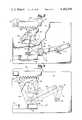
- FIG. 1, comprised of FIGS. 1a and 1b,is an exploded, pictorial view of the printing apparatus and improved tape-ribbon cartridge of the present invention.
- FIG. 2is a plan view, partially in section, showing the side of the rolling piston element and the means for actuating the printing cycle.
- FIG. 3is a plan view showing the printing force exerting piston at one of its end positions and showing the improved means for guiding and supporting the piston during the printing cycle.
- FIG. 4is a plan view of the printing force exerting piston, similar to FIG. 3, showing the piston in various positions during the printing cycle.
- FIG. 5is an exploded, pictorial view of the improved tape-ribbon cartridge of the present invention.
- FIG. 6is a plan view of the tape-ribbon cartridge of the present invention.
- FIG. 7is a sectional view of the tape-ribbon cartridge as viewed along the section lines 7--7 of FIG. 6.
- FIG. 8is a top view, partially in section, showing successive positions of the printing piston during the printing cycle.
- FIG. 9is a side view, partially in section, showing the printing piston and its relationship to the tape-ribbon cartridge during a printing cycle.
- FIG. 10is a cross sectional view showing the means for maintaining activation of the printing cycle.
- FIG. 1is an exploded, pictorial view of the printing apparatus and tape-ribbon cartridge of the present invention.
- the apparatus of the present inventionincludes a lower housing 10, a printing piston 11 for exerting a printing force toward a printing station, and a tape-ribbon cartridge 12 for supplying tape 78 and ribbon 79 to the printing station and for properly aligning and supporting a font element 14.
- the lower housing 10includes bottom and top members 15 and 16 and a pair of side members 18 and 19.
- the side members 18 and 19are secured at their upper edges to the lower surface of the top member 16 and at their lower edges to the upper surface of the bottom member 15.
- the members 15, 16, 18 and 19may be secured together either by screws, bolts, welds or any other appropriate means.
- an upper housingPositioned above the lower housing 10 is an upper housing defined by the frame member 16 and a vertically spaced frame member 20. These members 16 and 20 are joined together in spaced relationship to form an upper housing for the printing piston 11 and the tape-ribbon cartridge 12.
- the frame members 16 and 20are generally flat plates which are secured to each other in spaced relationship by the support brackets 21, 22 and 23 and by the pair of support posts 24 and 25.
- the bracket 21is fastened to a rearward surface of the support or printing piston rails 28 and 29 by the screws 27 and the brackets 22 and 23 are held in place between the plates 16 and 20 by tabs 22a protruding into slots 22b in the plates 16 and 20.
- the support posts 24 and 25are secured by the screws 26.
- Each of the inner surfaces of the frame members 16 and 20includes a printing piston rail 28 and 29, respectively, for guiding and supporting the printing piston 11 during a printing cycle.
- the rails 28 and 29are securely fastened to their respective members 16 and 20 by welding or other appropriate means.
- Disposed at each longitudinal end of the rails 28 and 29is an end rail section 30 and 31, respectively. As will be discussed in greater detail below, these end rail sections 30 and 31 support the printing piston 11 at each end of the printing cycle.
- These end rail sections 30 and 31are also rigidly secured to the frame members 16 and 20 by welding or other appropriate means.
- the printing piston 11includes a generally wedge-shaped roller segment 32 having a curved surface, a urethane pad 35 secured to the curved surface, a shoulder portion 34 conforming to the curvature of the curved surface and a pair of rollers or bearing members 36 rotatably supported on an axle or shaft 38.
- the roller shaft 38is journalled within portions 39 (FIG. 2) of the roller segment 32 to rotatably support the rollers 36 for rolling movement along the rails 28 and 29.
- rolling motionis imparted to the roller segment 32, and in particular the curved surface of the urethane pad 35, by an elongated connecting link 40 and a crank member 41.
- connecting link 40is rotatably connected with the bearing member shaft 38 while the other end of the link 40 is rotatably connected at the pivot 42 to the crank member 41.
- the other end of the crank member 41is secured to a shaft 44 associated with an electric motor 45 (FIG. 1b) for movement therewith.
- the connecting link 40is positioned between the portion 39.
- the radius of curvature of the curved urethane pad surface 35has its center at the axial center of the shaft or axle 38.
- the means for actuating the electric motor 45includes the elongated print or switch bar 46 and the force transfer links 48 and 50.
- the members 46 and 48are associated with each other with a surface of the bar 46 engaging a portion of the link 48 (FIG. 10), such that movement of the switch bar 46 toward the front of the printing apparatus moves the link 48 in a forward direction.
- the elongated link 48includes a downwardly extending portion 49 which engages a motion transfer link 50.
- the link 50is pivotally secured at its midpoint to a flange portion 51. Forward movement of the print bar 46, and thus link 48, causes clockwise movement of the link 50, thus releasing the switch member 53 of the microswitch 52.
- the electric motor 45(FIG. 1) provides rotational movement to the shaft 44.
- This rotational movementthrough the link 40 and the crank member 41, causes generally transverse rolling movement of the rollers 36 along the rails 28 and 29.
- the translational movement of the rollers 36is guided by first and second gear sections comprising the gear section or segment 56 and the associated gear rack 58.
- the gear section 56is securely fastened to the generally wedge-shaped roller segment 32 by a pair of bolts 61 and includes a plurality of gear teeth 59.
- the gear rack 58is securely fastened to the lower frame member 16 by the screws 62 and includes a plurality of gear teeth 60 adapted to mesh with the gear teeth 59 of the gear section 56.
- the teeth 59 of the gear segment 56maintain a constant engagement with the teeth 60 of the gear rack 58 to properly align the printing piston 11 (FIG. 1) in printing registration with the printing station.
- the pitch line of the gear segment 56coincides with the curved surface of the polyurethane pad 35. Therefore, as the printing piston 11 moves back and forth, the surface of the polyurethane pad 35 is moved along in true rolling contact motion with respect to the printing station.
- the gear teeth 59are positioned arcuately along an outer edge of the gear segment 56 and the gear teeth 60 are disposed along a straight line. It is contemplated however, that the gear and rack sections 56 and 58 could be reversed (i.e.) the rack 58 could be mounted to the roller segment 32 and the gear segment 56 mounted to the lower frame member 16. In fact, the corresponding gear teeth 59, 60 of the gear segment 56 and rack 58 could be disposed along various paths as long as the meshing of such teeth 59, 60 results in true rolling movement of the wedge-shaped roller segment 32 and in particular the curved surface of the pad 35 with respect to the printing station.
- FIGS. 3 and 4show the printing piston 11 in various positions during a printing cycle.
- FIG. 3shows the printing piston 11 in one of its end positions. In its end position, the rollers 36 are supported by the pair of end rail sections 30 and 31 disposed at each end of the support rails 28 and 29.
- a spring member 64 extending between one of the bolts 61 and the bracket 54causes the rollers 36 to be moved onto the end rail sections 30 and 31 at the end of each printing cycle, thereby causing generally rearward movement of the wedge-shaped roller segment 32 and the gear segment 56.
- rollers 36Upon commencement of a printing cycle, the rollers 36 move back upon the support rails 28 and 29 and the gear teeth 59 and 60 become engaged to cause the roller segment 32 to move in rolling movement with respect to the printing station such that a normal or perpendicular printing force is exerted against successive portions of the printing surface.
- the wedge-shaped roller segment 32 of the printing piston 11is disposed between and guided by the upper and lower frame members 20 and 16, respectively, while the gear segment 56 and the gear rack 58 are mounted below the lower frame member 16.
- an opening 65is provided in the frame member 16.
- the gear segment 56is mounted in spaced relationship with respect to the roller segment 32 to permit a portion of the frame 16 to extend between the two elements 56 and 32.
- the spacingis accomplished by the bushings or spacing members 63 associated with the bolts 61. It should be noted that the spacing members 63 may be separate bushings as shown in FIG. 2 or bosses integrally joined with the roller segment 32.
- a transparent glass window 66comprised of a solid glass block is disposed between the frame members 16 and 20 and between the support posts 24 and 25.
- a tranparent plastic safety window 68Positioned immediately forward of the glass block 66 is a tranparent plastic safety window 68 having a pair of shoulder portions 69 on each edge. When assembled, these shoulder portions 69 are engaged by the retaining rail members or brackets 70 which are rigidly secured to the opposing inner surfaces of the frame members 16 and 20.
- the rearward surface of the glass block 66defines the surface against which the printing force generated by the printing piston 11 is exerted. This exertion of printing pressure is then resisted by the plastic window 68 and ultimately by the pair of retaining brackets 70.
- the glass block 66is approximately 3/4 of an inch thick while the plastic window 68 is approximately 1/8 of an inch thick. It has been found that these thicknesses are sufficient to withstand the printing pressures created in the present apparatus which can be in excess of 2000 p.s.i.
- the combination of the glass window 66, the plastic window 68 and the retaining rail members 70function together as the means for resisting the printing force.
- the tape-ribbon cartridge 12is adapted for positioning between the frame members 16 and 20 to provide image carrying tape 78 and printing ribbon 79 to the printing station defined in part by the rearward face of the glass block 66.
- the tape-ribbon cartridge 12includes a cartridge body or housing 71 and an elongated tape guide portion or snout member 72 extending outwardly from the housing 71.
- the cartridge 12is retained within the printing apparatus by the support or cartridge retaining bracket 22.
- the tape guide portion 72is positioned immediately behind the glass block 66 and the housing 71 is retained by the bracket 22 and the spring clip member 74. In this position, one edge of the housing section 71a is engaged by the outwardly extending portion 33 of the bracket 22, while the opposite edge of the section 71a is engaged by the member 74.
- the cartridge housing 71is formed from a pair of housing sections 71a and 71b which are joined together by a plurality of connecting posts 75 and corresponding holes 76. Disposed within the housing 71 is a supply of image carrying adhesive backed tape 78 and a supply of colored toner ribbon 79.
- the ribbon 79can consist of a high-carbon content ribbon, although non-carbon toners can also be utilized.
- the supply of tape 78 and ribbon 79is in roll form, with each of the rolls being rotatably supported within the housing 71 by appropriate support members 80 and 81, respectively.
- a tape-ribbon divider 82which assists in guiding the tape 78 and ribbon 79 out of the housing 71 and also in maintaining separation between the tape 78 and ribbon 79 to prevent relative movement between the tape 78 and ribbon 79 during the feeding process. This, accordingly avoids the undesirable depositing of carbon from the ribbon 79 onto the tape 78 which is often caused by relative movement between the two surfaces.
- the divider 82is disposed within the housing 71 and includes a section 84 which extends outwardly from the housing 71 to continue guiding and separating the tape 78 and ribbon 79 for a portion of its travel along the snout member 72.
- the divider 82is a paper divider which has a smooth surface in contact with the ribbon 79 to prevent scratching the ribbon 79 during the feeding process.
- the snout member or tape guide portion 72is integrally joined with the housing section 71b and extends outwardly therefrom to support and guide the tape 78 and ribbon 79 during their movement into alignment with the printing station.
- the elongated snout member 72includes an opening 85 and an outer end section 86.
- a pair of sections 77define the side edges of the opening 85 and assist in guiding the tape 78 and ribbon 79 through the snout member 72.
- Associated with the end section 86is a corresponding tape-ribbon retaining clip member 88.
- the clip member 88includes a pair of end latch members 87 for appropriate connection with corresponding latch seats 91 in the end section 86 and a pair of tape engaging ribs 89.
- a foam pad 90is positioned between the members 86 and 88 to hold the tape and ribbon materials in contact with each other as they are dispensed from the tape-ribbon cartridge 12. As illustrated in FIG. 7, the tape 78 and ribbon 79 are fed between the members 86 and 88 with the foam pad 90 being disposed between the ribbon 79 and inner surface of the end section 86.
- the pair of ribs 89 formed on the inside surface of the member 88are used to facilitate the use of narrower printing materials by providing an additional guiding means so as to maintain an accurate center line position of the materials as they pass through the cartridge 12.
- the foam pad 90has sufficient composition to retain the tape 78 and ribbon 79 in contact with each other so as to avoid inadvertent or undesirable relative movement with respect to each other, but also sufficient resiliency and flexibility to avoid pressure which would result in the depositing of carbon from the ribbon 79 onto the tape material 78.
- the end section 86also includes a recessed portion 83 to permit manual grasping of the tape 78 and ribbon 79 for advancing the same.
- the tape guide portion or elongated snout member 72also includes means for guiding the font element 14 into printing alignment and for supporting the element 14 during a printing cycle.
- This meansincludes a pair of tab or support members 92 and a pair of side guide portions 94 to properly support and guide the printing font element or chip 14 into printing alignment. As illustrated in FIGS. 6 and 7, when the font element 14 is properly positioned, the bottom surface rests on the support tabs 92 while the side edges are guided and aligned horizontally by the side guide portions 94.
- the font chip 14is a generally rectangular shaped element having a raised character 95, a tab portion 96, and a plurality of alignment indicia 93.
- the raised portion of the character 95faces the opening 85 and the tab portion 96 extends above the tape-ribbon cartridge 12.
- the snout member or tape guide portion 72includes a recessed portion 97 immediately above the opening 85 to permit the element 14 with raised characters 95 thereon to be inserted into the cartridge 12 when the cartridge 12 is properly positioned within the apparatus.
- FIGS. 8 and 9show views of the printing roller segment 32 exerting a printing force aagainst the font element 14 during a printing cycle.
- the snout member 72When properly inserted, the snout member 72 is disposed immediately behind the glass block 66 and a portion of the snout member 72 forms a cavity to receive the font element 14. Such cavity is defined in part by the rearward surface of the glass window 66, forward portions of the snout member 72, the side guide portions 94 and the tab members 92.
- Disposed immediately to the rear of the font element 14are the tape and ribbon members 78 and 79 which extend across the opening 85 in the snout member 72.
- the tape 78includes an adhesive backed, image carrying film layer 78a and a supporting upper layer 78b.
- the urethane pad 35 secured to the curved surface of the roller segment 32presses against the raised characters 95 of the font element 14 with the tape 78 and ribbon 79 members disposed therebetween. This causes the transfer of an image of the raised character 95 from the carbon ribbon 79 to the image carrying tape 78.
- the roller segment 32is guided in its rolling movement in part by the inner surfaces of the frame member 16 and 20. Accordingly, the general thickness of the roller segment 32 is slightly smaller than the distance between the frame members 16 and 20 to allow freedom of movement therebetween. Additionally, the outer curved portion of the roller segment 32 has a reduced width to permit the outer curved portion and the urethane pad 35 to extend through the opening 85 to exert the necessary printing pressure against the font element 14.
- the machine operatorinserts the tape-ribbon supply cartridge 12 into the machine until the retaining latch 74 snaps into position to hold the cartridge 12 in place. In this position, the tape guide portion or snout member 72 is disposed immediately to the rear of the glass block 66.
- a type chip or font element 14 bearing the desired character 95is then selected from a container (not shown) and inserted down through the opening 43 (FIG. 1) in the top of the machine. As shown best in FIGS. 2, 8 and 9, the chip 14 is inserted into a cavity defined by the rearward face of the glass block 66 and portions of the snout member 72. The chip 14 is properly aligned and supported by the side guide portions 94 and the support tabs 92.
- the printing cycleis then initiated by pulling the print bar 46 on top of the machine forward. This movement releases the switch member 53 (FIG. 2) and activates the electric motor 45.
- the connecting link 40 and crank member 41transmit the force of the motor 45 to the printing piston 11 and causes the rollers 36 to move off the end rail sections 30 and 31 and onto the rails 28 and 29.
- the rollers 36roll along the support rails 28 and 29 traversing from one side to the other.
- a narrowed portion of the wedge-shaped roller segment 32 including the polyurethane pad 35 secured to the surface of such portionpasses through the opening 85 in the snout member 72 of the cartridge 12 and contacts the rear surface of the tape 78.
- the front rail members 70 secured to the top and bottom frame plates 20 and 16resist motion of the glass block 66 and plastic window 68 and thus the font element 14. This resistance results in significant printing force as the rolling piston 11 rolls across the support rails 28 and 29 from one side to the other.
- the distances which are involved between the roller segment 32 and the raised character 95 of the font-type chip 14 when inserted in printing alignmentare such that during the printing cycle the polyurethane pad 35 is compressed approximately 0.010 of an inch. This amount of compression generates the correct amount of pressure to transfer toner from the carbon ribbon 79 onto the surface of the tape 78. In the apparatus of the present invention, this can be about 2,000 pounds per square inch.
- the type chip 14 which has been printedis then removed from the machine by the operator and the next character 95 to be printed is inserted into the machine.
- the operatorcan view the new chip 14 through the glass and plastic windows 66 and 68.
- the operatorgrasps the tape 78 and ribbon 79 by hand, near the outer edge of the snout member 72 and pulls the tape 78 and ribbon 79 from the cartridge 12 until proper spacing is desired.
- the print bar 46is again pulled forward, thereby activating a further printing cycle.
- the tape 78 and ribbon 79are pulled out of the cartridge snout member 72 far enough so that the materials may be cut off with a scissors.
Landscapes
- Engineering & Computer Science (AREA)
- Mechanical Engineering (AREA)
- Impression-Transfer Materials And Handling Thereof (AREA)
- Handling Of Continuous Sheets Of Paper (AREA)
Abstract
Description
Claims (20)
Priority Applications (5)
| Application Number | Priority Date | Filing Date | Title |
|---|---|---|---|
| US06/103,749US4360278A (en) | 1979-12-17 | 1979-12-17 | Printing apparatus having interchangeable large character type fonts and tape-ribbon cartridge therefor |
| CA000366874ACA1163139A (en) | 1979-12-17 | 1980-12-16 | Tape-ribbon cartridge for a printing apparatus |
| MX185304AMX151010A (en) | 1979-12-17 | 1980-12-17 | IMPROVEMENTS TO A PRINTER DEVICE |
| JP17868580AJPS56123889A (en) | 1979-12-17 | 1980-12-17 | Printer using tape*ribbonncartridge |
| CA000442591ACA1179894A (en) | 1979-12-17 | 1983-12-05 | Printing apparatus |
Applications Claiming Priority (1)
| Application Number | Priority Date | Filing Date | Title |
|---|---|---|---|
| US06/103,749US4360278A (en) | 1979-12-17 | 1979-12-17 | Printing apparatus having interchangeable large character type fonts and tape-ribbon cartridge therefor |
Publications (1)
| Publication Number | Publication Date |
|---|---|
| US4360278Atrue US4360278A (en) | 1982-11-23 |
Family
ID=22296834
Family Applications (1)
| Application Number | Title | Priority Date | Filing Date |
|---|---|---|---|
| US06/103,749Expired - LifetimeUS4360278A (en) | 1979-12-17 | 1979-12-17 | Printing apparatus having interchangeable large character type fonts and tape-ribbon cartridge therefor |
Country Status (4)
| Country | Link |
|---|---|
| US (1) | US4360278A (en) |
| JP (1) | JPS56123889A (en) |
| CA (1) | CA1163139A (en) |
| MX (1) | MX151010A (en) |
Cited By (15)
| Publication number | Priority date | Publication date | Assignee | Title |
|---|---|---|---|---|
| US4480936A (en)* | 1983-01-24 | 1984-11-06 | K-Sun Corporation | Two-piece tape/ribbon cartridge |
| US4696590A (en)* | 1985-05-30 | 1987-09-29 | U.S. Philips Corporation | Printer having a guide for an insertable cassette which can hold data and transfer strips |
| US20050162710A1 (en)* | 2004-01-23 | 2005-07-28 | Eastman Kodak Company | Scanner with removable image guides |
| US9011028B2 (en) | 2009-03-31 | 2015-04-21 | Brother Kogyo Kabushiki Kaisha | Tape cassette |
| US9132682B2 (en) | 2009-03-31 | 2015-09-15 | Brother Kogyo Kabushiki Kaisha | Tape unit and tape cassette |
| US9352600B2 (en) | 2009-12-16 | 2016-05-31 | Brother Kogyo Kabushiki Kaisha | Tape cassette |
| US9409425B2 (en) | 2009-03-31 | 2016-08-09 | Brother Kogyo Kabushiki Kaisha | Tape cassette |
| US9427988B2 (en) | 2009-03-31 | 2016-08-30 | Brother Kogyo Kabushiki Kaisha | Tape cassette |
| US9498997B2 (en) | 2008-12-25 | 2016-11-22 | Brother Kogyo Kabushiki Kaisha | Tape cassette |
| US9533522B2 (en) | 2008-12-25 | 2017-01-03 | Brother Kogyo Kabushiki Kaisha | Tape cassette |
| US9566808B2 (en) | 2009-03-31 | 2017-02-14 | Brother Kogyo Kabushiki Kaisha | Tape cassette |
| US9573401B2 (en) | 2009-06-30 | 2017-02-21 | Brother Kogyo Kabushiki Kaisha | Tape cassette |
| US9656495B2 (en) | 2009-12-28 | 2017-05-23 | Brother Kogyo Kabushiki Kaisha | Tape cassette |
| CN112109459A (en)* | 2019-06-19 | 2020-12-22 | 精工爱普生株式会社 | Storage body and ribbon set |
| US12296580B2 (en) | 2009-03-31 | 2025-05-13 | Brother Kogyo Kabushiki Kaisha | Tape cassette |
Families Citing this family (2)
| Publication number | Priority date | Publication date | Assignee | Title |
|---|---|---|---|---|
| JPH0730355Y2 (en)* | 1988-06-20 | 1995-07-12 | カシオ計算機株式会社 | Thermal transfer device |
| JPH02106555A (en)* | 1988-10-14 | 1990-04-18 | Brother Ind Ltd | Tape containing cassette |
Citations (19)
| Publication number | Priority date | Publication date | Assignee | Title |
|---|---|---|---|---|
| US992461A (en)* | 1909-09-09 | 1911-05-16 | Robert O Vandercook | Proof printing-press. |
| US1042848A (en)* | 1909-02-08 | 1912-10-29 | Robert O Vandercook | Machine for printing proofs. |
| US1076084A (en)* | 1909-09-09 | 1913-10-21 | Robert O Vandercook | Proof printing-press. |
| US1137299A (en)* | 1913-05-05 | 1915-04-27 | Hall Printing Press Company | Printing-machine. |
| US1499582A (en)* | 1923-05-09 | 1924-07-01 | Laguionie Joseph | Typewriting machine |
| US2295210A (en)* | 1940-02-21 | 1942-09-08 | Sherman Haynes | Illuminated platen |
| US2422406A (en)* | 1943-04-08 | 1947-06-17 | Ronald A Gordon | Illumination for typewriters |
| US2930465A (en)* | 1958-09-09 | 1960-03-29 | Roovers Lotsch Corp | Marking device |
| GB926588A (en)* | 1961-03-24 | 1963-05-22 | Dymo Industries Inc | Coiled tape magazine for a tape embossing or marking machine |
| US3272120A (en)* | 1964-10-22 | 1966-09-13 | Addressograph Multigraph | Address printing machines with roller platens |
| US3294212A (en)* | 1965-03-04 | 1966-12-27 | Clary Corp | Paper loading device for data printer |
| US3455431A (en)* | 1968-03-07 | 1969-07-15 | Trustees Employees Savings | Method and apparatus for simultaneously moving a marking tape and other tape |
| US3532053A (en)* | 1967-05-29 | 1970-10-06 | Jay Benjamin Lieberman | Printing press for dry-offset printing |
| US3768619A (en)* | 1971-12-29 | 1973-10-30 | Addressograph Multigraph | Direct image composing machine having means to prevent pressure overload of printing characters |
| US3834507A (en)* | 1973-01-30 | 1974-09-10 | Kroy Ind Inc | Printing apparatus |
| US3912064A (en)* | 1973-01-30 | 1975-10-14 | Kroy Ind Inc | Printing apparatus with font alignment means |
| US4015700A (en)* | 1975-10-30 | 1977-04-05 | Kroy Industries Inc. | Tape advance mechanism |
| US4108556A (en)* | 1976-09-24 | 1978-08-22 | Kroy Industries, Inc. | Printing piston assembly |
| EP0007030A1 (en)* | 1978-07-07 | 1980-01-23 | Kroy Industries Inc. | Printing cartridge |
- 1979
- 1979-12-17USUS06/103,749patent/US4360278A/ennot_activeExpired - Lifetime
- 1980
- 1980-12-16CACA000366874Apatent/CA1163139A/ennot_activeExpired
- 1980-12-17MXMX185304Apatent/MX151010A/enunknown
- 1980-12-17JPJP17868580Apatent/JPS56123889A/enactiveGranted
Patent Citations (20)
| Publication number | Priority date | Publication date | Assignee | Title |
|---|---|---|---|---|
| US1042848A (en)* | 1909-02-08 | 1912-10-29 | Robert O Vandercook | Machine for printing proofs. |
| US992461A (en)* | 1909-09-09 | 1911-05-16 | Robert O Vandercook | Proof printing-press. |
| US1076084A (en)* | 1909-09-09 | 1913-10-21 | Robert O Vandercook | Proof printing-press. |
| US1137299A (en)* | 1913-05-05 | 1915-04-27 | Hall Printing Press Company | Printing-machine. |
| US1499582A (en)* | 1923-05-09 | 1924-07-01 | Laguionie Joseph | Typewriting machine |
| US2295210A (en)* | 1940-02-21 | 1942-09-08 | Sherman Haynes | Illuminated platen |
| US2422406A (en)* | 1943-04-08 | 1947-06-17 | Ronald A Gordon | Illumination for typewriters |
| US2930465A (en)* | 1958-09-09 | 1960-03-29 | Roovers Lotsch Corp | Marking device |
| GB926588A (en)* | 1961-03-24 | 1963-05-22 | Dymo Industries Inc | Coiled tape magazine for a tape embossing or marking machine |
| US3272120A (en)* | 1964-10-22 | 1966-09-13 | Addressograph Multigraph | Address printing machines with roller platens |
| US3294212A (en)* | 1965-03-04 | 1966-12-27 | Clary Corp | Paper loading device for data printer |
| US3532053A (en)* | 1967-05-29 | 1970-10-06 | Jay Benjamin Lieberman | Printing press for dry-offset printing |
| US3455431A (en)* | 1968-03-07 | 1969-07-15 | Trustees Employees Savings | Method and apparatus for simultaneously moving a marking tape and other tape |
| US3768619A (en)* | 1971-12-29 | 1973-10-30 | Addressograph Multigraph | Direct image composing machine having means to prevent pressure overload of printing characters |
| US3834507A (en)* | 1973-01-30 | 1974-09-10 | Kroy Ind Inc | Printing apparatus |
| US3912064A (en)* | 1973-01-30 | 1975-10-14 | Kroy Ind Inc | Printing apparatus with font alignment means |
| US4015700A (en)* | 1975-10-30 | 1977-04-05 | Kroy Industries Inc. | Tape advance mechanism |
| US4108556A (en)* | 1976-09-24 | 1978-08-22 | Kroy Industries, Inc. | Printing piston assembly |
| EP0007030A1 (en)* | 1978-07-07 | 1980-01-23 | Kroy Industries Inc. | Printing cartridge |
| US4226547A (en)* | 1978-07-07 | 1980-10-07 | Kroy Industries Inc. | Printing cartridge |
Cited By (67)
| Publication number | Priority date | Publication date | Assignee | Title |
|---|---|---|---|---|
| US4480936A (en)* | 1983-01-24 | 1984-11-06 | K-Sun Corporation | Two-piece tape/ribbon cartridge |
| US4696590A (en)* | 1985-05-30 | 1987-09-29 | U.S. Philips Corporation | Printer having a guide for an insertable cassette which can hold data and transfer strips |
| US20050162710A1 (en)* | 2004-01-23 | 2005-07-28 | Eastman Kodak Company | Scanner with removable image guides |
| US7428084B2 (en)* | 2004-01-23 | 2008-09-23 | Eastman Kodak Company | Scanner with removable image guides |
| US9656496B2 (en) | 2008-12-25 | 2017-05-23 | Brother Kogyo Kabushiki Kaisha | Tape cassette |
| US9511609B2 (en) | 2008-12-25 | 2016-12-06 | Brother Kogyo Kabushiki Kaisha | Tape cassette |
| US12304229B2 (en) | 2008-12-25 | 2025-05-20 | Brother Kogyo Kabushiki Kaisha | Tape cassette |
| US12233641B2 (en) | 2008-12-25 | 2025-02-25 | Brother Kogyo Kabushiki Kaisha | Tape cassette |
| US11479053B2 (en) | 2008-12-25 | 2022-10-25 | Brother Kogyo Kabushiki Kaisha | Tape cassette |
| US11285749B2 (en) | 2008-12-25 | 2022-03-29 | Brother Kogyo Kabushiki Kaisha | Tape cassette |
| US10744798B2 (en) | 2008-12-25 | 2020-08-18 | Brother Kogyo Kabushiki Kaisha | Tape cassette |
| US10661589B2 (en) | 2008-12-25 | 2020-05-26 | Brother Kogyo Kabushiki Kaisha | Tape cassette |
| US10189284B2 (en) | 2008-12-25 | 2019-01-29 | Brother Kogyo Kabushiki Kaisha | Tape cassette |
| US9682584B2 (en) | 2008-12-25 | 2017-06-20 | Brother Kogyo Kabushiki Kaisha | Tape cassette |
| US9855779B2 (en) | 2008-12-25 | 2018-01-02 | Brother Kogyo Kabushiki Kaisha | Tape cassette |
| US9498997B2 (en) | 2008-12-25 | 2016-11-22 | Brother Kogyo Kabushiki Kaisha | Tape cassette |
| US9498998B2 (en) | 2008-12-25 | 2016-11-22 | Brother Kogyo Kabushiki Kaisha | Tape cassette |
| US9511611B2 (en) | 2008-12-25 | 2016-12-06 | Brother Kogyo Kabushiki Kaisha | Tape cassette |
| US9511610B2 (en) | 2008-12-25 | 2016-12-06 | Brother Kogyo Kabushiki Kaisha | Tape cassette |
| US9751349B2 (en) | 2008-12-25 | 2017-09-05 | Brother Kogyo Kabushiki Kaisha | Tape cassette |
| US9522556B2 (en) | 2008-12-25 | 2016-12-20 | Brother Kogyo Kabushiki Kaisha | Tape cassette |
| US9533522B2 (en) | 2008-12-25 | 2017-01-03 | Brother Kogyo Kabushiki Kaisha | Tape cassette |
| US9539838B2 (en) | 2008-12-25 | 2017-01-10 | Brother Kogyo Kabushiki Kaisha | Tape Cassette |
| US9656497B2 (en) | 2008-12-25 | 2017-05-23 | Brother Kogyo Kabushiki Kaisha | Tape cassette |
| US9566812B2 (en) | 2008-12-25 | 2017-02-14 | Brother Kogyo Kabushiki Kaisha | Tape cassette |
| US9649861B2 (en) | 2008-12-25 | 2017-05-16 | Brother Kogyo Kabushiki Kaisha | Tape cassette |
| US11254149B2 (en) | 2009-03-31 | 2022-02-22 | Brother Kogyo Kabushiki Kaisha | Tape cassette |
| US9381756B2 (en) | 2009-03-31 | 2016-07-05 | Brother Kogyo Kabushiki Kaisha | Tape cassette |
| US9616690B2 (en) | 2009-03-31 | 2017-04-11 | Brother Kogyo Kabushiki Kaisha | Tape cassette |
| US9566808B2 (en) | 2009-03-31 | 2017-02-14 | Brother Kogyo Kabushiki Kaisha | Tape cassette |
| US9346296B2 (en) | 2009-03-31 | 2016-05-24 | Brother Kogyo Kabushiki Kaisha | Tape cassette |
| US12296580B2 (en) | 2009-03-31 | 2025-05-13 | Brother Kogyo Kabushiki Kaisha | Tape cassette |
| US9656488B2 (en) | 2009-03-31 | 2017-05-23 | Brother Kogyo Kabushiki Kaisha | Tape cassette |
| US9011028B2 (en) | 2009-03-31 | 2015-04-21 | Brother Kogyo Kabushiki Kaisha | Tape cassette |
| US9132682B2 (en) | 2009-03-31 | 2015-09-15 | Brother Kogyo Kabushiki Kaisha | Tape unit and tape cassette |
| US9498987B2 (en) | 2009-03-31 | 2016-11-22 | Brother Kogyo Kabushiki Kaisha | Tape cassette |
| US12257827B2 (en) | 2009-03-31 | 2025-03-25 | Brother Kogyo Kabushiki Kaisha | Tape cassette |
| US11945217B2 (en) | 2009-03-31 | 2024-04-02 | Brother Kogyo Kabushiki Kaisha | Tape cassette |
| US9498988B2 (en) | 2009-03-31 | 2016-11-22 | Brother Kogyo Kabushiki Kaisha | Tape cassette |
| US9427988B2 (en) | 2009-03-31 | 2016-08-30 | Brother Kogyo Kabushiki Kaisha | Tape cassette |
| US10201988B2 (en) | 2009-03-31 | 2019-02-12 | Brother Kogyo Kabushiki Kaisha | Tape cassette |
| US10201993B2 (en) | 2009-03-31 | 2019-02-12 | Brother Kogyo Kabushiki Kaisha | Tape cassette |
| US10226949B2 (en) | 2009-03-31 | 2019-03-12 | Brother Kogyo Kabushiki Kaisha | Tape cassette |
| US11707938B2 (en) | 2009-03-31 | 2023-07-25 | Brother Kogyo Kabushiki Kaisha | Tape cassette |
| US9370949B2 (en) | 2009-03-31 | 2016-06-21 | Brother Kogyo Kabushiki Kaisha | Tape cassette |
| US10744802B2 (en) | 2009-03-31 | 2020-08-18 | Brother Kogyo Kabushiki Kaisha | Tape cassette |
| US10675894B2 (en) | 2009-03-31 | 2020-06-09 | Brother Kogyo Kabushiki Kaisha | Tape cassette |
| US9592692B2 (en) | 2009-03-31 | 2017-03-14 | Brother Kogyo Kabushiki Kaisha | Tape cassette |
| US9409425B2 (en) | 2009-03-31 | 2016-08-09 | Brother Kogyo Kabushiki Kaisha | Tape cassette |
| US9403389B2 (en) | 2009-03-31 | 2016-08-02 | Brother Kogyo Kabushiki Kaisha | Tape cassette |
| US10618325B2 (en) | 2009-03-31 | 2020-04-14 | Brother Kogyo Kabushiki Kaisha | Tape cassette |
| US11052685B2 (en) | 2009-03-31 | 2021-07-06 | Brother Kogyo Kabushiki Kaisha | Tape cassette |
| US9802432B2 (en) | 2009-06-30 | 2017-10-31 | Brother Kogyo Kabushiki Kaisha | Tape cassette |
| US9676217B2 (en) | 2009-06-30 | 2017-06-13 | Brother Kogyo Kabushiki Kaisha | Tape cassette |
| US11225099B2 (en) | 2009-06-30 | 2022-01-18 | Brother Kogyo Kabushiki Kaisha | Tape cassette |
| US9573401B2 (en) | 2009-06-30 | 2017-02-21 | Brother Kogyo Kabushiki Kaisha | Tape cassette |
| US12194765B2 (en) | 2009-06-30 | 2025-01-14 | Brother Kogyo Kabushiki Kaisha | Tape cassette |
| US11235600B2 (en) | 2009-12-16 | 2022-02-01 | Brother Kogyo Kabushiki Kaisha | Tape cassette |
| US10265976B2 (en) | 2009-12-16 | 2019-04-23 | Brother Kogyo Kabushiki Kaisha | Tape cassette |
| US9352600B2 (en) | 2009-12-16 | 2016-05-31 | Brother Kogyo Kabushiki Kaisha | Tape cassette |
| US9539837B2 (en) | 2009-12-16 | 2017-01-10 | Brother Kogyo Kabushiki Kaisha | Tape cassette |
| US10265982B2 (en) | 2009-12-28 | 2019-04-23 | Brother Kogyo Kabushiki Kaisha | Tape cassette |
| US12128697B2 (en) | 2009-12-28 | 2024-10-29 | Brother Kogyo Kabushiki Kaisha | Tape cassette |
| US11135862B2 (en) | 2009-12-28 | 2021-10-05 | Brother Kogyo Kabushiki Kaisha | Tape cassette with indicator portion having pressing and non-pressing portion for indentifying tape type |
| US9656495B2 (en) | 2009-12-28 | 2017-05-23 | Brother Kogyo Kabushiki Kaisha | Tape cassette |
| EP3756899A1 (en)* | 2019-06-19 | 2020-12-30 | Seiko Epson Corporation | Container and tape ribbon set |
| CN112109459A (en)* | 2019-06-19 | 2020-12-22 | 精工爱普生株式会社 | Storage body and ribbon set |
Also Published As
| Publication number | Publication date |
|---|---|
| CA1163139A (en) | 1984-03-06 |
| MX151010A (en) | 1984-09-06 |
| JPH035990B2 (en) | 1991-01-28 |
| JPS56123889A (en) | 1981-09-29 |
Similar Documents
| Publication | Publication Date | Title |
|---|---|---|
| US4360278A (en) | Printing apparatus having interchangeable large character type fonts and tape-ribbon cartridge therefor | |
| US4300847A (en) | Teleprinter having single belt carriage and ribbon drive system | |
| DE68923715T3 (en) | Thermal printer | |
| DD233101B5 (en) | postage meter | |
| DE3119025C2 (en) | Printing device | |
| US2503185A (en) | Bed and platen hectographic address machine | |
| US3838641A (en) | Portable, lightweight imprinting apparatus | |
| EP0054575B1 (en) | Printing apparatus and tape-ribbon cartridge therefor | |
| US4382835A (en) | Composite label arranging device | |
| US4108556A (en) | Printing piston assembly | |
| CA1179894A (en) | Printing apparatus | |
| US2306616A (en) | Typewriter attachment for manifolding | |
| US3022998A (en) | Printing apparatus | |
| US3561353A (en) | Printing apparatus employing embossed type in metallic foil | |
| US2010137A (en) | Duplicating attachment for typewriters | |
| CA1056752A (en) | Printing apparatus having improved spacing means | |
| US3070009A (en) | Burster imprinter | |
| US1929449A (en) | Work sheet guiding means | |
| US1911237A (en) | Machine for forming adhesive paper strips | |
| US2074778A (en) | Typewriter | |
| US3349699A (en) | Label printing machine | |
| US1937750A (en) | Flexible stencil card and holder therefor | |
| US1140493A (en) | Attachment for type-writers, adding-machines, and the like. | |
| US3820458A (en) | Elimination of uncontrolled background reproduction during printing | |
| JPS5739975A (en) | Printing device |
Legal Events
| Date | Code | Title | Description |
|---|---|---|---|
| AS | Assignment | Owner name:KROY INC. Free format text:CHANGE OF NAME;ASSIGNOR:KROY INDUSTRIES INC.;REEL/FRAME:004045/0618 Effective date:19820322 | |
| STCF | Information on status: patent grant | Free format text:PATENTED CASE | |
| AS | Assignment | Owner name:FIRST NATIONAL BANK OF MINNEAPOLIS, A NATIONAL BAN Free format text:SECURITY INTEREST;ASSIGNOR:KROY, INC., A CORP OF MN.;REEL/FRAME:004716/0308 Effective date:19861218 | |
| AS | Assignment | Owner name:KROY, INC. Free format text:RELEASED BY SECURED PARTY;ASSIGNOR:FIRST BANK NATIONAL ASSOCIATION;REEL/FRAME:005691/0018 Effective date:19901116 Owner name:STANCHART BUSINESS CREDIT, INC., ILLINOIS Free format text:SECURITY INTEREST;ASSIGNOR:KROY, INC.;REEL/FRAME:005709/0013 Effective date:19901116 | |
| AS | Assignment | Owner name:NATIONAL CANADA FINANCE CORPORATION, ILLINOIS Free format text:SECURITY INTEREST;ASSIGNOR:KROY, INC.;REEL/FRAME:007437/0380 Effective date:19950410 | |
| AS | Assignment | Owner name:KROY, INC., ARIZONA Free format text:MORTGAGE;ASSIGNOR:LASALLE BUSINESS CREDIT, INC. F/K/A STANCHART BUSINESS CREDIT, INC.;REEL/FRAME:007570/0187 Effective date:19950412 | |
| AS | Assignment | Owner name:KROY, LLC, OHIO Free format text:ASSIGNMENT OF ASSIGNORS INTEREST;ASSIGNOR:KROY, INC.;REEL/FRAME:009564/0722 Effective date:19971231 | |
| AS | Assignment | Owner name:KROY, LLC, OHIO Free format text:MERGER;ASSIGNOR:KROY, INC.;REEL/FRAME:009556/0190 Effective date:19971231 |