US4360277A - Portable fabric temperature profiler - Google Patents
Portable fabric temperature profilerDownload PDFInfo
- Publication number
- US4360277A US4360277AUS06/221,811US22181180AUS4360277AUS 4360277 AUS4360277 AUS 4360277AUS 22181180 AUS22181180 AUS 22181180AUS 4360277 AUS4360277 AUS 4360277A
- Authority
- US
- United States
- Prior art keywords
- wire
- probe
- reel
- web
- temperature
- Prior art date
- Legal status (The legal status is an assumption and is not a legal conclusion. Google has not performed a legal analysis and makes no representation as to the accuracy of the status listed.)
- Expired - Fee Related
Links
Images


Classifications
- G—PHYSICS
- G01—MEASURING; TESTING
- G01K—MEASURING TEMPERATURE; MEASURING QUANTITY OF HEAT; THERMALLY-SENSITIVE ELEMENTS NOT OTHERWISE PROVIDED FOR
- G01K13/00—Thermometers specially adapted for specific purposes
- G01K13/04—Thermometers specially adapted for specific purposes for measuring temperature of moving solid bodies
- G01K13/06—Thermometers specially adapted for specific purposes for measuring temperature of moving solid bodies in linear movement
- B—PERFORMING OPERATIONS; TRANSPORTING
- B65—CONVEYING; PACKING; STORING; HANDLING THIN OR FILAMENTARY MATERIAL
- B65H—HANDLING THIN OR FILAMENTARY MATERIAL, e.g. SHEETS, WEBS, CABLES
- B65H75/00—Storing webs, tapes, or filamentary material, e.g. on reels
- B65H75/02—Cores, formers, supports, or holders for coiled, wound, or folded material, e.g. reels, spindles, bobbins, cop tubes, cans, mandrels or chucks
- B65H75/34—Cores, formers, supports, or holders for coiled, wound, or folded material, e.g. reels, spindles, bobbins, cop tubes, cans, mandrels or chucks specially adapted or mounted for storing and repeatedly paying-out and re-storing lengths of material provided for particular purposes, e.g. anchored hoses, power cables
- B65H75/38—Cores, formers, supports, or holders for coiled, wound, or folded material, e.g. reels, spindles, bobbins, cop tubes, cans, mandrels or chucks specially adapted or mounted for storing and repeatedly paying-out and re-storing lengths of material provided for particular purposes, e.g. anchored hoses, power cables involving the use of a core or former internal to, and supporting, a stored package of material
- B65H75/40—Cores, formers, supports, or holders for coiled, wound, or folded material, e.g. reels, spindles, bobbins, cop tubes, cans, mandrels or chucks specially adapted or mounted for storing and repeatedly paying-out and re-storing lengths of material provided for particular purposes, e.g. anchored hoses, power cables involving the use of a core or former internal to, and supporting, a stored package of material mobile or transportable
Definitions
- the temperature profileis the record of the changing temperature of a single spot on a component such as a moving fabric.
- an accurate temperature profileis especially useful in the textile industry in general, and particularly in textile fabric heat-setting and drying.
- the oven temperatureis commonly set at a predetermined level based on the operator's past experience and only after problems develop, whether they are overheating, underheating, or side-to-side variation, is a correction made in oven temperature, etc. Little assurance of the correct operating condition appropriate for a required time and temperature profile is provided. Because of this, various proposals and techniques have been tried with a view toward obtaining an accurate temperature profile, i.e., temperature history.
- One proposed technique for obtaining a fabric temperature profileis to mount a temperature sensor together with electronic processor and memory device on the moving fabric web as it moves through the oven.
- This systemstores and records a temperature profile of the fabric as it rides along through the oven with the fabric.
- Such a systemis not practical, however, due to the expense of selecting appropriate components that can withstand the oven temperatures while passing through the oven, the large mass of the system, and the high cost of replacement when a sensor is damaged.
- a further proposal, adapted for use in baking ovens,is to insert a probe into the article being baked and send the probe, along with other components which together form a transmitter, through the oven.
- the signal from the moving transmitteris beamed out of the oven to a stationary receiver which then receives and interprets the signal.
- Transistorsare noted to be present in at least two of the components utilized. Since the temperature of the oven is normally above the maximum operating temperature of any normally available transistors, the unit is encased in heat insulating material and surrounded by a further enclosure containing solid carbon dioxide. Such an arrangement is impractical since the cooling source must be continuously replenished. Additionally, the temperature probe provided for such a system is not readily adaptable for use with a fabric web, and the components of the system are relatively complicated and expensive.
- the apparatus according to the present inventionis simple, inexpensive, and easy to use. While the apparatus is particularly adapted for use in temperature profiling of moving fabric webs, it also has applicability to other temperature profiling systems wherein the temperature profile of a moving substrate or web is desired.
- the apparatus according to the present inventionis capable of simply and accurately determining the temperature profile of a fabric web in a drying or heat-setting oven or the like without requiring interruption of the fabric processing.
- the term "oven” as used hereinis meant to include only those ovens where the progress of goods or components through them is along substantially straight and usually horizontal paths, as in a textile tenter oven.
- a temperature profile of a moving fabric web in a textile treating assemblyis obtained utilizing a temperature sensing probe interconnected by a reeled wire to a monitor.
- the temperature sensing probe--with wire attached--is placed in operative engagement with a specific point of the fabric web, the probe maintaining contact with the point of the web and moving therewith into the entrance of the textile treating assembly.
- the probeis mounted on a structure having fabric engaging and penetrating sharpened pins so that when the probe supporting structure is merely laid on the moving web the pins penetrate and engage the web while the probe is held in contact therewith.
- Unreeling of the wireis effected as the probe moves with the fabric web through the textile treating assembly, and the temperature of the specific point of the fabric web is continuously measured by monitoring the temperature data supplied by the probe. Desirably the temperature data are continuously recorded, with the data used immediately or subsequently to effect correction of operational parameters associated with the textile treating assembly.
- the probeWithout the fabric web movement being arrested the probe is disconnected from the web after it exits the textile treating assembly, and the wire is reeled up. Between the disconnection and reeling steps, preferably the wire is disconnected from the probe so that the wire alone is pulled back through the textile treating assembly while the probe, and its mounting structure, are carried back to the assembly entrance.
- the reelrotates about an axis to let out the take up the wire while making continuous electrical contact between the wire and the monitor during wire let out and take up, and wire take up may be effected by manually rotating the reel about its axis of rotation and effecting level wind of the wire. If desired, means may instead be provided for winding up the wire with a small electric or the like motor.
- the word "wire” as used hereinis inclusive of the combinations of two or more separate wires or leads comprising or connected to thermocouples, thermistors, resistance thermometers, or the like, as will be obvious to one of ordinary skill in the field of the invention.
- a temperature profiler for a moving substrateincludes as the two major components a means for engaging the substrate, and a means ensuring transmission of the temperature information from the substrate-engaging means to a useful point. Both such means are in themselves unique.
- the means for engaging the substrate to move therewith and determine the temperature of a predetermined point thereonincludes a support, a contactor mounted to the support, a temperature probe, and a release electrical connector.
- the substrate contactorincludes at least one sharpened fabric-penetrating pin mounted on the underside of the support.
- the temperature probewhich preferably comprises a thermocouple, is mounted to the support to extend into operative relationship with the substrate.
- a handleis preferably provided mounted to the top of the support to allow ready retrieval of the probe from the moving substrate once it traverses its predetermined path, although an automatic removal mechanism may be utilized instead.
- the structure utilized for transmitting the temperature data from the probe to a suitable monitoring pointincludes a wire reel, an elongated electrically conductive wire, means for mounting the reel for rotation about an axis while providing electrical continuity between the wire and an electrically conductive member stationary with respect to the reel, and means for connecting the stationary electrically conductive member to a monitoring device, such as a recorder.
- the wireis wrapped around the periphery of the reel and an electrical connector, compatible with the releasable connector at the substrate-engaging means, is mounted on one end thereof. The operator holds a handle extending from the reel and not rotatable therewith to support the reel at the entrance to the traversal path of the substrate.
- Level winding and unwinding of the wireis controlled by an extension arm, level with mechanism, and wire controlling arms biased into contact with the wire around the periphery of the reel.
- the operatorcan manually rotate the reel about its axis to effect winding of the wire back onto the reel.
- FIG. 1is a top plan view of an exemplary fabric-engaging component of the apparatus according to the present invention
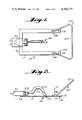
- FIG. 2is a side view of the apparatus component of FIG. 1;
- FIG. 3is a bottom plan view of an exemplary reeling assembly comprising a component part of the apparatus according to the invention
- FIG. 4is a side view of the apparatus component of FIG. 3 shown in conjunction with a recorder;
- FIG. 5is a schematic view, partly in cross-section and partly in elevation, illustrating operation of the level wind mechanism of the apparatus of FIG. 4;
- FIG. 6is a side view showing the traveling apparatus component of FIGS. 1 and 2 connected to a fabric web in temperature-monitoring relationship therewith;
- FIG. 7is a schematic view illustrating an exemplary manner of utilization of the apparatus of FIGS. 1 through 6 in practicing a method of fabric temperature profiling according to the invention
- FIG. 8is a typical temperature profile that may be obtained during practice of the method of the invention, with reference to FIG. 7;
- FIG. 9is a partial detail view of exemplary wire control means of the apparatus of FIGS. 3 and 4.
- FIGS. 1, 2 and 6One apparatus component according to the present invention for securing a temperature profile of a moving substrate, such as a fabric web, is illustrated most clearly in FIGS. 1, 2 and 6 generally at reference numeral 10.
- the apparatus 10actually engages the moving substrate to be profiled, moving with the substrate as it traverses its path.
- the apparatus 10includes an elongated support 11 having a first end 12 and a second end 13.
- the preferred form of the supportis a generally U-shaped plate-like member, with the base of the U defining the second end 13, and the tips of the arms of the U defining the first end 12.
- Mounted to the bottom surface of the support 11is at least one substrate contactor.
- the at least one contactoris formed as a plurality of fabric pins 15, each pin being sharpened to a point 16 so that it is capable of penetrating and engaging a fabric web F or the like (see FIG. 6).
- the sharpened points 16penetrate the web and ensure that the support 11 will be stationary with respect to the area of the web contacted.
- the pins 15are mounted adjacent the first end of the support 11, adjacent the tips of the arms of the U.
- the apparatus 10further includes a temperature probe for determining substrate temperature, the probe being illustrated generally at 18 in the drawings.
- a temperature probefor determining substrate temperature
- the probebeing illustrated generally at 18 in the drawings.
- a number of different probe elementscan be used, such as thermistors or resistance thermometers, but the preferred form of the probe illustrated in the drawing is a thermocouple having a thermocouple junction 19.
- probe 18 and associated componentsare mostly described in terms of the probe being a thermocouple, and thermocouple junction 19 the point of contact with the web.
- Thermocouple wire 20leads from junction 19 to a connection means, such as a male thermocouple plug 21 mounted on the top of support 11 adjacent the second end 13 thereof.
- connection meanssuch as a male thermocouple plug 21 mounted on the top of support 11 adjacent the second end 13 thereof.
- the corresponding electrical connectionssuch as wires and junction plugs must be so selected that they are compatible with the particular probe element, as is well known in the art.
- thermocouple wires 20are joined to make the smallest practical junction 19, from the smallest practical wire.
- This combinationshows a time response which, though the time lag is about the maximum allowable, is at least as fast as the fabric response to heat transfer. Since so small a thermocouple wire inevitably tends to exhibit high electrical resistance, only that portion of the wire from junction 19 to plug 21 is small, the remaining and much longer portions back to the external recorder being made of 0.020-inch iron-constantan.
- Meansare provided for mounting the temperature probe 18 to the support 11 between the first and second ends 12, 13 thereof so that the probe 18 extends below the support 11 into operative engagement with the web.
- the probe 18is mounted between the arms of the U-shaped support 11 as well as between the ends 12, 13 thereof.
- a spring wire 22is cantilevered from the support 11 to the probe 18 and provides means for resiliently biasing the thermocouple junction 19 into direct contact with the top surface of the fabric web F (see FIG. 6).
- a molded epoxy or phenolic insulating connector 24unites thermocouple wire 20 and associated thermocouple junction 19 with spring 22, as most clearly seen in FIG. 2.
- the end of the spring 22 opposite its connection to the probe 18is operatively connected to the support 11, as to the bracket 23 which in turn is screwed to the base of the U-shaped support 11, and receives the male thermocouple plug 21.
- a retrieval handle 25For ready retrieval of the device 10 from the moving web after the device has traversed the predetermined path to be profiled with the web, a retrieval handle 25 is provided.
- the handle 25includes base portions 26 thereof which are connected to the top surface of the support 11 (as to the tops of the U-arms thereof), and has a grasping portion 27 extending upwardly from the base portions 26 and past the first end 12 of the support 11, remote from the second end 13 thereof. An operator standing adjacent the moving web may readily grab the grasping portion 27 and pull upwardly on it to remove the whole device 10 from the web.
- an automatic meansmay be provided for removing the device 10 from the moving web, such as a powerful magnet placed above the area of removal.
- the component according to the present invention for carrying and controlling the wire provided for transmitting the temperature signal obtained from the probe 18 back to a stationary monitor remote from the probeis illustrated most clearly in FIGS. 3 through 5, and is indicated generally by reference numeral 30.
- the device 30includes a reel 31 having a peripheral portion 32 onto which a wire may be wound.
- a thermocouple wire 33is wrapped around the reel periphery 32.
- the wire 33has a female thermocouple connector 34 mounted at one end thereof.
- the connector 34is compatible with the wire and the male connector 21. When the connectors 21, 34 is engaged (see FIG. 6) the thermocouple junction 19 is electrically connected through wire 20, and the connectors, to wire 33.
- the device 30further comprises means for mounting the reel for rotation about an axis A--A (see FIG. 4) to take up and let out the wire 33 while providing electrical continuity between the wire 33 and further compatible thermocouple wire 36 stationary with respect to the reel 31.
- Meansare also provided, such as a thermocouple plug 38 attached to the end of wire 36, for connecting wire 36 to a monitoring device for receiving temperature data from the probe 18 through the wire 33.
- the monitoring devicepreferably comprises a dual channel strip chart recorder, such as a Hewlett-Packard Recorder Model 7100B, illustrated generally at 39 in FIG. 4.
- the means for mounting the reel 31 for rotation about the axis A--Apreferably includes shaft 41 connected to and extending from the center of the reel 31 coextensive with the axis A--A and having enclosed a conventional slip ring assembly, illustrated schematically at 42 in FIG. 5.
- the slip ring assemblymay comprise any suitable conventional type such as Model SR2 manufactured by Omega Engineering, Inc.
- a handle 43surrounds the shaft 41, the handle not being rotatable with the reel 31.
- the device 30further includes wire control means for providing let-out and take-up of wire 33 from and to the reel 31 from a predetermined area of the reel periphery.
- wire control meansincludes an extension arm 44 extending radially outwardly from the handle 43 and stationarily mounted thereto.
- the extension arm 44may include a housing portion 45 and a rod portion 46, a wire guide 47 being provided on the end of the rod 46 remote from the handle 43, the wire 33 passing through the guide 47.
- the guide 47 and connector 34are preferably dimensioned so that the connector 34 cannot pass through the guide 47.
- the wire control meansfurther comprises a level wind mechanism illustrated generally at 49.
- the level wind mechanism 49ensures that the wire 33 is wrapped around the reel 31 without overlap so that there will be no snags during take-up and let-out.
- the level wind mechanismconsists of a track cam 50, follower 51, wire guide 52, drive belt 53 and associated belt gears 54, 55.
- the belt gear 55is fastened on shaft 41, and as reel 31 rotates provides power through drive belt 53 to gear belt 54.
- This gear 54is mounted on the end of cam 50, so as the reel moves the wire guide 52 causes wire 33 to move across the reel 31 face making uniform layers. Due to the track design on the cam 50, when the follower 51 gets to one end of the cam 50 it reverses, letting a new row of wire 33 begin.
- the wire control meansfurther includes a pair of horizontal wire controlling arms 58 which are mounted on the extension arm 44 (e.g. to the top of housing 45) and are spring biased by a spring 59 so that leaf springs 60, attached to vertical extensions 61 of arms 58, engage the wire 33 on the reel 31, a spring 60 being provided on either side of the level wind mechanism 49 (see FIGS. 3 and 4).
- the connection of the arms 58 to the top of housing 45is a pivotal connection (not shown) so that the arms 58 are pivotal with respect to each other and with respect to housing 45 under the influence of biasing spring 59.
- Each of the two tear-shaped anti-ballooning leaf springs 60has attached thereto, on opposite sides of the spring loops, two polytetrafluoroethylene wear pads 62 (see FIG. 9), each of which serves in turn, depending upon the direction in which the spring is pointing, as the primary contact surface of the spring against wire 33.
- the padsare coextensive with the width of peripheral surface 32 of reel 31, such that the wire around the reel is held down firmly by the pads.
- the springsmay assume either of the positions illustrated on the right or left in FIG. 9, depending upon whether the wire is being wound or unwound on the reel 31.
- the device 30further comprises means attached to the reel 31 to effect active rotation thereof about the axis A--A.
- Such meansmay comprise a powered component, or--as illustrated in the drawings--may comprise a handle 63 (see FIG. 4) attached to a perimeter portion of the reel 31 on the opposite side thereof from the handle 43, and elongated in a dimension parallel to the axis A--A.
- An operator grasping handle 63 and acting upon itcan effect manual rotation of the reel 31 about the axis A--A.
- an on-off switch 64(see FIG. 3 in particular) may be provided mounted on the bottom of the handle 43, with appropriate wiring 65 (see FIG. 4) leading from the switch 64 to and from the recorder 39, the recorder being plugged into a suitable power source.
- an event marker(momentary switch) may also be operatively mounted on the bottom of handle 43, as illustrated schematically at 66 in FIG. 3.
- FIG. 7schematically illustrates utilization of the apparatus heretofore described in practicing the fabric temperature profiling method according to the invention with respect to a fabric web F moving through a drying/heat-setting oven 68.
- One operatorstands at the entrance 69 to the oven 68, and another operator stands at the exit 70 from the oven. All apparatus components are initially located at the entrance side 69.
- the connectors 21, 34are joined, the wires 36, 65 are connected up to the recorder 39, and the power is turned on so that the recorder warms up.
- the recorder 39is placed so that it is easily visible to the operator at the entrance 69, but need not be directly next to him since the switch 64 allows remote operation of the chart movement mechanism of the recorder 39.
- the operator at entrance 69grasps the device 10 by handle 25 and lays it on the moving fabric web F, without arresting the fabric web movement, so that the sharpened points 16 of pins 15 penetrate the fabric.
- the cantilever spring 22biases the thermocouple junction 19 into contact with the top surface of the web F, and the switch 64 is actuated to start the recorder chart movement.
- continuous temperature dataare provided by the thermocouple junction 19 through wire 20, connectors 21 and 34, and wire 33, and subsequently through slip ring 42 to wire 36 on to the recorder 39.
- a typical temperature profile that is obtained in oven 68is illustrated in FIG. 8, the actual profile illustrated in FIG. 8 being for a three-zone Procter and Schwartz tenter oven when treating 100% polyester textured woven fabric.
- the wire 33is continuously unwound from the reel 31.
- the operator at the exit 70 from the oven 68grasps the portion 27 of handle 25 and lifts the device 10 off the fabric F.
- the operator at the entrance 69shuts off the recorder 39 utilizing switch 64 while the operator at the exit 70 preferably detaches the connectors 21, 34 so that the wire 33 may be pulled through the oven 68 by itself.
- the device 10is then carried back to the entrance 69 for another run, while the operator at entrance 69, holding handle 43, rotates the reel 31 using handle 63, the level wind mechanism 49 ensuring that the wire 33 is properly wound onto the reel periphery 32.
- the operatormay then immediately, or subsequently, determine operational parameters that need be adjusted in order to optimize quality and uniformity of treatment, minimize energy consumption, et cetera.
Landscapes
- Physics & Mathematics (AREA)
- General Physics & Mathematics (AREA)
- Treatment Of Fiber Materials (AREA)
Abstract
Description
Claims (21)
Priority Applications (2)
| Application Number | Priority Date | Filing Date | Title |
|---|---|---|---|
| US06/221,811US4360277A (en) | 1980-12-31 | 1980-12-31 | Portable fabric temperature profiler |
| US06/614,389US4488014A (en) | 1980-12-31 | 1984-05-25 | Reeling assembly |
Applications Claiming Priority (1)
| Application Number | Priority Date | Filing Date | Title |
|---|---|---|---|
| US06/221,811US4360277A (en) | 1980-12-31 | 1980-12-31 | Portable fabric temperature profiler |
Related Child Applications (1)
| Application Number | Title | Priority Date | Filing Date |
|---|---|---|---|
| US06411617Division | 1982-08-26 |
Publications (1)
| Publication Number | Publication Date |
|---|---|
| US4360277Atrue US4360277A (en) | 1982-11-23 |
Family
ID=22829490
Family Applications (1)
| Application Number | Title | Priority Date | Filing Date |
|---|---|---|---|
| US06/221,811Expired - Fee RelatedUS4360277A (en) | 1980-12-31 | 1980-12-31 | Portable fabric temperature profiler |
Country Status (1)
| Country | Link |
|---|---|
| US (1) | US4360277A (en) |
Cited By (33)
| Publication number | Priority date | Publication date | Assignee | Title |
|---|---|---|---|---|
| EP0125743A3 (en)* | 1983-05-06 | 1985-05-08 | Burlington Industries, Inc. | Nozzle velocity measuring |
| US5356218A (en)* | 1993-05-04 | 1994-10-18 | Motorola, Inc. | Probe for providing surface images |
| US5642578A (en)* | 1994-12-29 | 1997-07-01 | U.S. Philips Corporation | Flat-iron comprising a thermal detector which measures a fabric temperature |
| US5820266A (en)* | 1996-12-10 | 1998-10-13 | Fedak; Tibor J. | Travelling thermocouple method & apparatus |
| EP1245937A1 (en)* | 2001-03-28 | 2002-10-02 | Reflowtech International Limited | Monitoring system |
| WO2005080663A1 (en)* | 2004-02-17 | 2005-09-01 | Noveon Ip Holdings Corp. | Textile finishing temperature monitoring systems and method |
| US7038172B1 (en)* | 2003-05-16 | 2006-05-02 | Marshall Air Systems, Inc. | Conveyorized food broiling apparatus |
| US20080184827A1 (en)* | 2007-02-02 | 2008-08-07 | The Board Of Regents Of The Nevada System Of Higher Ed. On Behalf Of The Desert Research Inst. | Monitoring probes and methods of use |
| US7658196B2 (en) | 2005-02-24 | 2010-02-09 | Ethicon Endo-Surgery, Inc. | System and method for determining implanted device orientation |
| US7775966B2 (en) | 2005-02-24 | 2010-08-17 | Ethicon Endo-Surgery, Inc. | Non-invasive pressure measurement in a fluid adjustable restrictive device |
| US7775215B2 (en) | 2005-02-24 | 2010-08-17 | Ethicon Endo-Surgery, Inc. | System and method for determining implanted device positioning and obtaining pressure data |
| US7844342B2 (en) | 2008-02-07 | 2010-11-30 | Ethicon Endo-Surgery, Inc. | Powering implantable restriction systems using light |
| US7927270B2 (en) | 2005-02-24 | 2011-04-19 | Ethicon Endo-Surgery, Inc. | External mechanical pressure sensor for gastric band pressure measurements |
| US8016745B2 (en) | 2005-02-24 | 2011-09-13 | Ethicon Endo-Surgery, Inc. | Monitoring of a food intake restriction device |
| US8016744B2 (en) | 2005-02-24 | 2011-09-13 | Ethicon Endo-Surgery, Inc. | External pressure-based gastric band adjustment system and method |
| US8034065B2 (en) | 2008-02-26 | 2011-10-11 | Ethicon Endo-Surgery, Inc. | Controlling pressure in adjustable restriction devices |
| US8057492B2 (en) | 2008-02-12 | 2011-11-15 | Ethicon Endo-Surgery, Inc. | Automatically adjusting band system with MEMS pump |
| US8066629B2 (en) | 2005-02-24 | 2011-11-29 | Ethicon Endo-Surgery, Inc. | Apparatus for adjustment and sensing of gastric band pressure |
| US8100870B2 (en) | 2007-12-14 | 2012-01-24 | Ethicon Endo-Surgery, Inc. | Adjustable height gastric restriction devices and methods |
| US8114345B2 (en) | 2008-02-08 | 2012-02-14 | Ethicon Endo-Surgery, Inc. | System and method of sterilizing an implantable medical device |
| US8142452B2 (en) | 2007-12-27 | 2012-03-27 | Ethicon Endo-Surgery, Inc. | Controlling pressure in adjustable restriction devices |
| US8152710B2 (en) | 2006-04-06 | 2012-04-10 | Ethicon Endo-Surgery, Inc. | Physiological parameter analysis for an implantable restriction device and a data logger |
| US8187162B2 (en) | 2008-03-06 | 2012-05-29 | Ethicon Endo-Surgery, Inc. | Reorientation port |
| US8187163B2 (en) | 2007-12-10 | 2012-05-29 | Ethicon Endo-Surgery, Inc. | Methods for implanting a gastric restriction device |
| US8192350B2 (en) | 2008-01-28 | 2012-06-05 | Ethicon Endo-Surgery, Inc. | Methods and devices for measuring impedance in a gastric restriction system |
| US8221439B2 (en) | 2008-02-07 | 2012-07-17 | Ethicon Endo-Surgery, Inc. | Powering implantable restriction systems using kinetic motion |
| US8233995B2 (en) | 2008-03-06 | 2012-07-31 | Ethicon Endo-Surgery, Inc. | System and method of aligning an implantable antenna |
| US8337389B2 (en) | 2008-01-28 | 2012-12-25 | Ethicon Endo-Surgery, Inc. | Methods and devices for diagnosing performance of a gastric restriction system |
| US8377079B2 (en) | 2007-12-27 | 2013-02-19 | Ethicon Endo-Surgery, Inc. | Constant force mechanisms for regulating restriction devices |
| US8591395B2 (en) | 2008-01-28 | 2013-11-26 | Ethicon Endo-Surgery, Inc. | Gastric restriction device data handling devices and methods |
| US8591532B2 (en) | 2008-02-12 | 2013-11-26 | Ethicon Endo-Sugery, Inc. | Automatically adjusting band system |
| US8870742B2 (en) | 2006-04-06 | 2014-10-28 | Ethicon Endo-Surgery, Inc. | GUI for an implantable restriction device and a data logger |
| CN105300537A (en)* | 2015-11-18 | 2016-02-03 | 国网山东省电力公司莱芜供电公司 | Portable temperature measuring device of wires and electrical appliances |
Citations (8)
| Publication number | Priority date | Publication date | Assignee | Title |
|---|---|---|---|---|
| US2441562A (en)* | 1944-11-25 | 1948-05-18 | Leon R Chase | Continuous reading thermocouple temperature measuring device for rotary vessles |
| US3333476A (en)* | 1962-11-13 | 1967-08-01 | Lyons & Co Ltd J | Temperature measuring apparatus |
| US3533288A (en)* | 1968-09-24 | 1970-10-13 | John M Franck | Magnetic drag thermocouple |
| US3540280A (en)* | 1968-04-11 | 1970-11-17 | Edward Orton Jr Ceramic Founda | Temperature monitoring apparatus |
| US3871212A (en)* | 1973-05-04 | 1975-03-18 | Goodyear Tire & Rubber | System and method for monitoring quality characteristics of a moving web |
| US3875799A (en)* | 1971-08-24 | 1975-04-08 | Wira & Mather | Devices for sensing the temperature of a moving web |
| US4046009A (en)* | 1976-04-23 | 1977-09-06 | Swiss Aluminium Ltd. | Thermocouple for continuously measuring the temperature along the length of a surface |
| US4104917A (en)* | 1977-01-13 | 1978-08-08 | James E. Rieth | Trolling wire |
- 1980
- 1980-12-31USUS06/221,811patent/US4360277A/ennot_activeExpired - Fee Related
Patent Citations (8)
| Publication number | Priority date | Publication date | Assignee | Title |
|---|---|---|---|---|
| US2441562A (en)* | 1944-11-25 | 1948-05-18 | Leon R Chase | Continuous reading thermocouple temperature measuring device for rotary vessles |
| US3333476A (en)* | 1962-11-13 | 1967-08-01 | Lyons & Co Ltd J | Temperature measuring apparatus |
| US3540280A (en)* | 1968-04-11 | 1970-11-17 | Edward Orton Jr Ceramic Founda | Temperature monitoring apparatus |
| US3533288A (en)* | 1968-09-24 | 1970-10-13 | John M Franck | Magnetic drag thermocouple |
| US3875799A (en)* | 1971-08-24 | 1975-04-08 | Wira & Mather | Devices for sensing the temperature of a moving web |
| US3871212A (en)* | 1973-05-04 | 1975-03-18 | Goodyear Tire & Rubber | System and method for monitoring quality characteristics of a moving web |
| US4046009A (en)* | 1976-04-23 | 1977-09-06 | Swiss Aluminium Ltd. | Thermocouple for continuously measuring the temperature along the length of a surface |
| US4104917A (en)* | 1977-01-13 | 1978-08-08 | James E. Rieth | Trolling wire |
Cited By (38)
| Publication number | Priority date | Publication date | Assignee | Title |
|---|---|---|---|---|
| EP0125743A3 (en)* | 1983-05-06 | 1985-05-08 | Burlington Industries, Inc. | Nozzle velocity measuring |
| US4573353A (en)* | 1983-05-06 | 1986-03-04 | Burlington Industries, Inc. | Method and apparatus for obtaining a nozzle velocity profile of a tenter oven |
| US5356218A (en)* | 1993-05-04 | 1994-10-18 | Motorola, Inc. | Probe for providing surface images |
| US5388323A (en)* | 1993-05-04 | 1995-02-14 | Motorola, Inc. | Method of forming a probe for an atomic force microscope |
| US5642578A (en)* | 1994-12-29 | 1997-07-01 | U.S. Philips Corporation | Flat-iron comprising a thermal detector which measures a fabric temperature |
| US5820266A (en)* | 1996-12-10 | 1998-10-13 | Fedak; Tibor J. | Travelling thermocouple method & apparatus |
| EP1245937A1 (en)* | 2001-03-28 | 2002-10-02 | Reflowtech International Limited | Monitoring system |
| US7038172B1 (en)* | 2003-05-16 | 2006-05-02 | Marshall Air Systems, Inc. | Conveyorized food broiling apparatus |
| WO2005080663A1 (en)* | 2004-02-17 | 2005-09-01 | Noveon Ip Holdings Corp. | Textile finishing temperature monitoring systems and method |
| US20050209936A1 (en)* | 2004-02-17 | 2005-09-22 | Guy Stephen L | Textile finishing temperature monitoring systems and method |
| US8016744B2 (en) | 2005-02-24 | 2011-09-13 | Ethicon Endo-Surgery, Inc. | External pressure-based gastric band adjustment system and method |
| US8066629B2 (en) | 2005-02-24 | 2011-11-29 | Ethicon Endo-Surgery, Inc. | Apparatus for adjustment and sensing of gastric band pressure |
| US7775966B2 (en) | 2005-02-24 | 2010-08-17 | Ethicon Endo-Surgery, Inc. | Non-invasive pressure measurement in a fluid adjustable restrictive device |
| US7775215B2 (en) | 2005-02-24 | 2010-08-17 | Ethicon Endo-Surgery, Inc. | System and method for determining implanted device positioning and obtaining pressure data |
| US7927270B2 (en) | 2005-02-24 | 2011-04-19 | Ethicon Endo-Surgery, Inc. | External mechanical pressure sensor for gastric band pressure measurements |
| US8016745B2 (en) | 2005-02-24 | 2011-09-13 | Ethicon Endo-Surgery, Inc. | Monitoring of a food intake restriction device |
| US7658196B2 (en) | 2005-02-24 | 2010-02-09 | Ethicon Endo-Surgery, Inc. | System and method for determining implanted device orientation |
| US8152710B2 (en) | 2006-04-06 | 2012-04-10 | Ethicon Endo-Surgery, Inc. | Physiological parameter analysis for an implantable restriction device and a data logger |
| US8870742B2 (en) | 2006-04-06 | 2014-10-28 | Ethicon Endo-Surgery, Inc. | GUI for an implantable restriction device and a data logger |
| US7793559B2 (en) | 2007-02-02 | 2010-09-14 | Board Of Regents Of The Nevada System Of Higher Education, On Behalf Of The Desert Research Institute | Monitoring probes and methods of use |
| US20080184827A1 (en)* | 2007-02-02 | 2008-08-07 | The Board Of Regents Of The Nevada System Of Higher Ed. On Behalf Of The Desert Research Inst. | Monitoring probes and methods of use |
| US8187163B2 (en) | 2007-12-10 | 2012-05-29 | Ethicon Endo-Surgery, Inc. | Methods for implanting a gastric restriction device |
| US8100870B2 (en) | 2007-12-14 | 2012-01-24 | Ethicon Endo-Surgery, Inc. | Adjustable height gastric restriction devices and methods |
| US8377079B2 (en) | 2007-12-27 | 2013-02-19 | Ethicon Endo-Surgery, Inc. | Constant force mechanisms for regulating restriction devices |
| US8142452B2 (en) | 2007-12-27 | 2012-03-27 | Ethicon Endo-Surgery, Inc. | Controlling pressure in adjustable restriction devices |
| US8591395B2 (en) | 2008-01-28 | 2013-11-26 | Ethicon Endo-Surgery, Inc. | Gastric restriction device data handling devices and methods |
| US8337389B2 (en) | 2008-01-28 | 2012-12-25 | Ethicon Endo-Surgery, Inc. | Methods and devices for diagnosing performance of a gastric restriction system |
| US8192350B2 (en) | 2008-01-28 | 2012-06-05 | Ethicon Endo-Surgery, Inc. | Methods and devices for measuring impedance in a gastric restriction system |
| US8221439B2 (en) | 2008-02-07 | 2012-07-17 | Ethicon Endo-Surgery, Inc. | Powering implantable restriction systems using kinetic motion |
| US7844342B2 (en) | 2008-02-07 | 2010-11-30 | Ethicon Endo-Surgery, Inc. | Powering implantable restriction systems using light |
| US8114345B2 (en) | 2008-02-08 | 2012-02-14 | Ethicon Endo-Surgery, Inc. | System and method of sterilizing an implantable medical device |
| US8057492B2 (en) | 2008-02-12 | 2011-11-15 | Ethicon Endo-Surgery, Inc. | Automatically adjusting band system with MEMS pump |
| US8591532B2 (en) | 2008-02-12 | 2013-11-26 | Ethicon Endo-Sugery, Inc. | Automatically adjusting band system |
| US8034065B2 (en) | 2008-02-26 | 2011-10-11 | Ethicon Endo-Surgery, Inc. | Controlling pressure in adjustable restriction devices |
| US8187162B2 (en) | 2008-03-06 | 2012-05-29 | Ethicon Endo-Surgery, Inc. | Reorientation port |
| US8233995B2 (en) | 2008-03-06 | 2012-07-31 | Ethicon Endo-Surgery, Inc. | System and method of aligning an implantable antenna |
| CN105300537A (en)* | 2015-11-18 | 2016-02-03 | 国网山东省电力公司莱芜供电公司 | Portable temperature measuring device of wires and electrical appliances |
| CN105300537B (en)* | 2015-11-18 | 2017-12-22 | 国网山东省电力公司莱芜供电公司 | Portable wire electrical equipment temperature measuring equipment |
Similar Documents
| Publication | Publication Date | Title |
|---|---|---|
| US4360277A (en) | Portable fabric temperature profiler | |
| US4488014A (en) | Reeling assembly | |
| US4151458A (en) | Closely spaced pipe-to-soil electrical survey method and apparatus | |
| US8995099B2 (en) | Control system for electrical cord reel | |
| DE3475361D1 (en) | Magnetic tape loading devices | |
| CA2393263C (en) | Automated cable handling and transport apparatus and vehicle | |
| CN113281687A (en) | Superconducting long belt critical current continuous measurement device and measurement method thereof | |
| US3879594A (en) | Temperature measurement and control of rotating surfaces | |
| GB1587529A (en) | Apparatus for monitoring thread breakage | |
| US4942351A (en) | System for monitoring a level of material, device therefor and methods of making the same | |
| US4573011A (en) | Method and apparatus for testing electro-mechanical devices | |
| US3407895A (en) | Self-controlled tractor guidance system | |
| US5820266A (en) | Travelling thermocouple method & apparatus | |
| US3635777A (en) | Apparatus for emplacing filament-shaped materials into thermoplastic materials, methods for using said apparatus and products produced thereby | |
| CN117387534A (en) | Outer diameter size detection device for sensor cables at different temperatures | |
| US3410745A (en) | Apparatus for adapting slide fasteners to be heat sealed in place | |
| EP0244123B1 (en) | Cable supporting apparatus | |
| US3039430A (en) | Machine for applying helical stripe to wire | |
| JPH0228526A (en) | Method and device for measuring surface temperature of moving body | |
| US2957688A (en) | System for heat treating continuous punched strip | |
| US4058219A (en) | Method and apparatus for automatically testing reeled axial-lead electrical devices under environmental conditions | |
| ATE160896T1 (en) | CLEANING DEVICE FOR VIDEO PLAYERS/RECORDERS | |
| US3264631A (en) | Indicating gauge including a chain-like member wrapped about a major portion of the circumference of the gauged wire-like continuous moving web for indicating irregularities in the web circumference | |
| KR101013515B1 (en) | On-site heat flux measuring device of hot rolled cooling process and heat flux measuring method using the same | |
| SU1737282A1 (en) | Device for determining thermal electric nonuniformity of thermocouple wire |
Legal Events
| Date | Code | Title | Description |
|---|---|---|---|
| AS | Assignment | Owner name:BURLINGTON INDUSTRIES, INC., GREENSBORO, NC A CORP Free format text:ASSIGNMENT OF ASSIGNORS INTEREST;ASSIGNORS:DANIEL VERNON T.;ROBBINS EDWARD J.;WANG KENNETH Y.;REEL/FRAME:003850/0457 Effective date:19801212 | |
| MAFP | Maintenance fee payment | Free format text:PAYMENT OF MAINTENANCE FEE, 4TH YEAR, PL 96-517 (ORIGINAL EVENT CODE: M170); ENTITY STATUS OF PATENT OWNER: LARGE ENTITY Year of fee payment:4 | |
| AS | Assignment | Owner name:BURLINGTON INDUSTRIES, INC. Free format text:ASSIGNMENT OF ASSIGNORS INTEREST.;ASSIGNOR:BURLINGTON INDUSTRIES, INC.;REEL/FRAME:004821/0756 Effective date:19870903 Owner name:BURLINGTON INDUSTRIES, INC. Free format text:MERGER;ASSIGNOR:BI/MS HOLDS I INC.;REEL/FRAME:004827/0512 Effective date:19870903 Owner name:BURLINGTON INDUSTRIES, INC.,STATELESS Free format text:MERGER;ASSIGNOR:BI/MS HOLDS I INC.;REEL/FRAME:004827/0512 Effective date:19870903 Owner name:BURLINGTON INDUSTRIES, INC. Free format text:ASSIGNMENT OF ASSIGNORS INTEREST;ASSIGNOR:BURLINGTON INDUSTRIES, INC.;REEL/FRAME:004821/0756 Effective date:19870903 | |
| FEPP | Fee payment procedure | Free format text:PAYOR NUMBER ASSIGNED (ORIGINAL EVENT CODE: ASPN); ENTITY STATUS OF PATENT OWNER: LARGE ENTITY | |
| MAFP | Maintenance fee payment | Free format text:PAYMENT OF MAINTENANCE FEE, 8TH YEAR, PL 96-517 (ORIGINAL EVENT CODE: M171); ENTITY STATUS OF PATENT OWNER: LARGE ENTITY Year of fee payment:8 | |
| AS | Assignment | Owner name:CHEMICAL BANK A NY BANKING CORPORATION Free format text:LIEN;ASSIGNORS:BURLINGTON INDUSTRIES, INC., A DE CORPORATION;BURLINGTON FABRICS INC., A DE CORPORATION;B.I. TRANSPORTATION, INC.;REEL/FRAME:006054/0351 Effective date:19920319 | |
| FEPP | Fee payment procedure | Free format text:MAINTENANCE FEE REMINDER MAILED (ORIGINAL EVENT CODE: REM.); ENTITY STATUS OF PATENT OWNER: LARGE ENTITY | |
| LAPS | Lapse for failure to pay maintenance fees | ||
| FP | Lapsed due to failure to pay maintenance fee | Effective date:19941123 | |
| STCH | Information on status: patent discontinuation | Free format text:PATENT EXPIRED DUE TO NONPAYMENT OF MAINTENANCE FEES UNDER 37 CFR 1.362 |